九州大学学術情報リポジトリ
Kyushu University Institutional Repository
A STUDY ON REPAIR STRATEGY OF SEVERELY DAMAGED RC STRUCTURES BY USING SACRIFICIAL ANODE
CATHODIC PROTECTION
ピンタ, アストゥティ
http://hdl.handle.net/2324/4110492
出版情報:九州大学, 2020, 博士(工学), 課程博士 バージョン:
権利関係:
A STUDY ON REPAIR STRATEGY OF
SEVERELY DAMAGED RC STRUCTURES BY USING SACRIFICIAL ANODE CATHODIC
PROTECTION
深刻な損傷を受けた RC 構造物の犠牲陽極方式 電気防食による補修工法に関する研究
PINTA ASTUTI
Acknowledgments
After an intensive period of my doctoral study, today is the day, writing this note of acknowledgments is the finishing touch on my doctoral thesis. It has been a period of intense learning for me, not only in the scientific arena but also on a personal level. Writing this dissertation has had a significant impact on me. I would like to reflect on the people who have supported me so much throughout this period.
I would like to express my special appreciation and sincere gratitude to my supervisor Prof. Hidenori HAMADA, for his patience, motivation, enthusiasm, endless encouragement, immense knowledge and guidance throughout my three years of doctoral study and my new life in Japan. He has always been available to advise me even he is busy with his daily routine work, make him a very great supervisor. He inspired me about the art of research in repair techniques of seriously damaged structures. Thank you for your kindness and for accepting me three years ago to experience your extensive knowledge in Concrete Engineering.
My thousands of appreciation also goes to the advisory committee, Prof. Koji TAKEWAKA, Assoc. Prof. Shigenobu KAINUMA, Assoc. Prof. Yasutaka SAGAWA, and Assoc. Prof. Tomoyuki KOYAMA for their precious suggestions and insightful comments concerning improve this research work. Thank you also for letting my defense be a memorable moment in my life.
My thanks also go to Dr. Daisuke YAMAMOTO for his tremendous help, precious friendship during my study and his non-stop support throughout my experimental work.
Thanks also to Assist. Prof. Takayuki FUKUNAGA for his assistance during this last half- year in laboratory.
My special gratitude also is dedicated to the Japan International Cooperation Agency (JICA) project for AUN/SEED-Net for providing financial study assistance during my doctoral program in Japan. My grateful acknowledgment also to PS. Mitsubishi Construction Co. Ltd. and DENKA Co. Ltd. for their support by providing material in this research.
My grateful appreciation is also addressed to Dr. Eng. Rahmita Sari Rafdinal and Dr.
Eng. Maki KODA for patient and kindness in guiding and helping me during collaborative research with their company.
My appreciation and thank also extends to present and past members of Concrete Engineering Laboratory for helping me through thick and thin time. Thank you for working together during specimen preparations. Thank you for the memorable technical site visit, laboratory party, excellent work environment, and fun chat. My thanks also go to Khalilah binti Khamarulzaman, Loke Yen Theng, Volana Andriamisa, Zhang Yi Chen, Xie Caiyun, Sabrina Harahap, and Dr. Eng. Dahlia Patah who actively supported this research.
Thank you very much also addresses to the colleagues of the Department of Civil Engineering, Faculty of Engineering, Universitas Muhammadiyah Yogyakarta, Indonesia for supporting me during my study at Kyushu University, Japan. Thank you also to Bapak Jazaul Ikhsan, Ph.D. and Bapak Puji Harsanto, Ph.D. who motivated me to finish my study on time and always appreciated my achievement during my study.
I would also like to take this opportunity to express the profound gratitude of my sincere heart to my beloved parents and Dr. Eng. Adhitya Yoga Purnama for their love, wise counsel, a sympathetic ear, patience, and unstopable support during my study in Japan. I love you all!
Finally, there are my friends. We were not only able to support each other by deliberating over our research problems but also happily by talking about everything other than just our academics.
Thank you very much!
Pinta
Fukuoka, 2020.
i
Abstract
Chloride induced corrosion is one of the major causes of RC structures deterioration in the marine environment that leads to performance degradation and premature failure before the expected service life. From the literature, cathodic protection (CP) is one of the reliable repairing methods that proven to control chloride-induced corrosion. Therefore, sacrificial anodes, which is one of CP types with less instrument and maintenance requirement, have been used to limit the extent of concrete replacement due to chloride contamination and extend the service life of damaged RC structures. However, the specification of the repair method by sacrificial anodes in RC members is still unclear. The objective of this study is to find a suitable repair strategy on naturally damaged RC beam structures by sacrificial anodes cathodic protection. This dissertation consists mainly of seven chapters.
Chapter 1 explains the background of the study, research objectives and limitations, research contribution and standing point, and dissertation arrangement.
Chapter 2 describes the literature review from the previous study related to the durability issues in the RC structures due to chloride-induced corrosion; corrosion inspection, assessment, and monitoring method; and repair method of chloride-induced corrosion in RC structures.
Chapter 3 presents the fundamental research on the utilization of sacrificial anodes in laboratory cases. From the viewpoint of arresting macro-cell corrosion due to different chloride contamination after five years of observation, the point sacrificial anodes in the repair part is still generating protection to the segmented steel bars indicated by the depolarization test value. The longer the span of repair part, the higher depolarization value.
In the preparation of sacrificial anodes application, rust removal process on steel surface in repair concrete is the most desirable initial condition of steel bars when the sacrificial anode is applied to it. Regarding the temperature in the exposure condition, it can be reported that the application of sacrificial anodes in low temperature around -17°C performs a good result until three years but four years of utilization sacrificial anodes in high temperature (40°C) presents not effective protection due to crack formed around the steel bar protected by anodes. The experiment to reduce the high anode consumption in the early connection was
ii
succeeded in the last part of this chapter by the implementation of half of the initial sacrificial anodes current flow by using the impressed-current method.
Chapter 4 demonstrates repair methods by sacrificial anodes cathodic protection in more than 40-years severely damaged RC beams. RC-1 and RC-2 present the application of sacrificial anodes in patch repair to protect patch area only due to the electrochemical incompatibility of polymer mortar and existing concrete and after one year, the additional sacrificial anodes were applied in the non-patch repair. Both RC-1 and RC-2 show good protection identified by depolarization and improved steel bar conditions in all cross- sectional of the beams. RC-3 and RC-4 present the application of sacrificial anodes in non- patch repair only while the corrosion inhibitor was painted in the steel bar surface in the patch repair area. The corrosion inhibitor membrane reduces the required electric current for attaining the steel bar potential change in the patch repair. So, the application of corrosion inhibitor is recommended in RC structures repaired by sacrificial anodes. From RC-1~RC- 4, it can be seen that small current flow generated by sacrificial anodes affects not only on polarization but also modifies the steel bar condition. Depolarization values of more than 100 mV cannot have a significant effect on the improvement of steel bar conditions. The application of sacrificial anodes in the patch and non-patch repair is also presented in RC-5.
The obtained result indicates that the repair method by combining a different kind of sacrificial anodes in the patch and non-patch repair presented no significant polarization of rebar nor current flow. Therefore, the combined sacrificial anodes in the patch and non-patch repair method at the same time with closed distance could not be suitable repairing system.
Chapter 5 illustrates the utilization of titanium wire sensors as a new embeddable corrosion monitoring sensor in four RC members repaired by sacrificial anodes cathodic protection. Titanium wires sensor (TWS) is working as a corrosion monitoring sensor in concrete with stable potential reading in around the areas wherein it is embedded until 18 months of exposure. It is indicated by the stable potential development of sensors vs. time and current density of sacrificial anodes.
Chapter 6 formulates the proper sacrificial anode cathodic protection application method in the deteriorated RC beams. The installation of sacrificial anodes in patch repair deliver limited protection in patch repair only. If the sacrificial anodes were installed in existing concrete, it could cover protection not only in existing concrete but also in some part of patch repair. The application of sacrificial anodes both in the patch and in non-patch repair can protect a bigger area, but the time-lapse application is important. The design
iii
parameters of SACP application including environmental conditions, structural deterioration degree, and repairing technology are performed by the different protective current density and depolarization set values.
Chapter 7 conveys a summary, conclusion, and recommendation for future research.
iv
v
Table of Contents
Acknowledgments ... i
Abstract ... i
Table of Contents ... v
List of Tables ... xi
List of figures ... xiii
CHAPTER I General Introduction ... 1
1.1 Background of study ... 1
1.2 Research objective and limitation ... 3
1.3 Research contribution and standing point ... 3
1.4 Dissertation arrangement ... 3
1.5 References ... 5
CHAPTER II State of the art on repair strategy by sacrificial anodes cathodic protection in RC structures ... 7
2.1 Introduction ... 7
2.2 Durability of RC structures ... 7
2.2.1 Corrosion mechanism ... 9
2.2.2 Chloride-induced corrosion ... 13
2.2.3 Forms of corrosion ... 14
2.2.4 Electrochemical aspects of corrosion in concrete ... 16
2.3 Corrosion inspection, assessment, and monitoring ... 25
2.3.1 Half-cell potential mapping ... 26
2.3.2 Resistivity of concrete ... 29
2.3.3 Corrosion rate ... 32
2.3.4 Chloride determination ... 35
vi
2.3.5 Corrosion monitoring ... 37
2.4 Repair method of chloride-induced corrosion damaged RC structures by cathodic protection ... 38
2.4.1 Impressed current cathodic protection (ICCP) ... 42
2.4.2 Sacrificial anodes cathodic protection (SACP) ... 45
2.4.3 Performance Criteria of Cathodic Protection in Concrete ... 51
2.5 Summary of problem to be solved ... 55
2.6 References ... 55
CHAPTER III Fundamental study on the effectiveness of sacrificial anodes in RC members ... 61
3.1 Overview ... 61
3.2 Effect of non-homogeneous chloride contamination ... 61
3.2.1 Introduction ... 61
3.2.2 Experimental program ... 63
3.2.3 Result and discussion ... 66
3.2.4 Conclusion ... 74
3.3 Effect of the rust removal process of steel bar ... 75
3.3.1 Introduction ... 75
3.3.2 Experimental program ... 76
3.3.3 Results and discussion ... 79
3.3.4 Conclusion ... 84
3.4 Effect of low and high temperature ... 85
3.4.1 Introduction ... 85
3.4.2 Experimental program ... 86
3.4.3 Results and discussion ... 89
3.4.4 Conclusion ... 98
3.5 Experiment on hybrid cathodic protection ... 99
vii
3.5.1 Introduction ... 99
3.5.2 Experimental program ... 101
3.5.3 Result and discussion ... 103
3.5.4 Conclusion ... 105
3.6 Conclusion of fundamental study ... 106
3.7 References ... 106
CHAPTER IV Repair method of severely damaged RC beams by using sacrificial anode cathodic protection (SACP) ... 109
4.1 Introduction ... 109
4.2 Objectives ... 110
4.3 Detail of structures ... 110
4.3.1 Geometry of structures ... 110
4.3.2 Materials ... 111
4.3.3 Exposure condition history ... 111
4.4 Investigation of structures before repair process ... 112
4.4.1 Materials quality ... 112
4.4.2 Defective appearance and cracking pattern ... 113
4.4.3 Corrosion probability of rebar ... 117
4.4.4 Chloride ion concentration ... 119
4.5 Repair strategy ... 120
4.5.1 Repair design and materials ... 120
4.5.2 Repair process ... 123
4.6 Measurement method ... 124
4.6.1 Protective current density ... 124
4.6.2 Half-cell potential test (Ecorr) ... 125
4.6.3 Depolarization test ... 125
4.6.4 Polarization resistance and corrosion current density ... 126
viii
4.6.5 Anodic-cathodic polarization curve ... 126
4.7 Application of sacrificial anodes in patch and non-patch repair ... 127
4.7.1 Protective current density of sacrificial anodes ... 129
4.7.2 Potential development of sacrificial anodes ... 130
4.7.3 Anodic polarization behavior of sacrificial anodes ... 131
4.7.4 Potential development of steel bar ... 134
4.7.5 Anodic and cathodic polarization behavior of steel bar ... 143
4.7.6 Polarization resistance ... 145
4.7.7 Corrosion current density ... 145
4.7.8 Service life prediction of anodes in existing concrete ... 146
4.7.9 Actual specimen condition after two-years of repair ... 148
4.7.10 Conclusion ... 151
4.8 Application of sacrificial anodes in non-patch repair and corrosion inhibitor ... 151
4.8.1 Protective current density ... 153
4.8.2 Potential development of sacrificial anodes ... 154
4.8.3 Anodic polarization behavior of anodes ... 154
4.8.4 Potential development of steel bar ... 156
4.8.5 Anodic and cathodic polarization behavior of steel bar ... 161
4.8.6 Polarization resistance ... 163
4.8.7 Corrosion current density ... 164
4.8.8 Service life prediction of anodes in existing concrete ... 165
4.8.9 Actual specimen condition after two-years of repair ... 167
4.8.10 Conclusion ... 169
4.9 Application of different kinds of sacrificial anodes in patch and non-patch repair . 170 4.9.1 Current flow of sacrificial anodes ... 172
4.9.2 Polarization of anodes ... 172
4.9.3 Conclusion ... 174
ix
4.10 Discussion ... 175
4.11Conclusion of application of sacrificial anodes in severely damaged RC beams . 176 4.12 References ... 178
CHAPTER V Utilization of new embeddable corrosion monitoring sensor in repaired RC members ... 181
5.1 Introduction ... 181
5.2 Embeddable corrosion monitoring sensor ... 182
5.3 Application of sensor in existing concrete during repair process by sacrificial anodes in patch ad non-patch repair concrete ... 185
5.3.1 Specimen design ... 185
5.3.2 Measurement methods ... 186
5.3.3 Potential development of embeddable corrosion monitoring sensor ... 187
5.3.4 Potential development of steel bars measured by the new embeddable sensor and standard reference electrode ... 187
5.4 Application of embeddable corrosion monitoring sensor in patch and non-patch repair concrete during sacrificial anodes cathodic protection ... 190
5.4.1 Specimen design ... 190
5.4.2 Measurement methods ... 192
5.4.3 Potential development of embeddable corrosion monitoring sensor ... 194
5.4.4 Potential development of steel bars measured by new embeddable sensor and standard reference electrode ... 194
5.5 Stability of embeddable corrosion monitoring sensor ... 199
5.6 Conclusion ... 202
5.7 References ... 202
CHAPTER VI Design of appropriate repairing method by using sacrificial anodes cathodic protection in RC structures ... 205
6.1 Introduction ... 205
x
6.2 Review of SACP design for RC structures exposed to marine environment ... 206
6.3 Review of SACP monitoring and maintenance in RC structures ... 207
6.4 Discussion and recommendation of effective repair method by SACP for deteriorated RC structures ... 209
6.5 Conclusion ... 211
6.6 References ... 212
CHAPTER VII Conclusion and recommendation ... 213
7.1 Summary ... 213
7.2 Overview of contributions and conclusions ... 214
7.3 Recommendation for future research ... 216
xi
List of Tables
Table 2.1 Definition of deterioration stages due to chloride attack ... 9
Table 2.2 Criteria for diagnosis of deterioration degree ... 9
Table 2.3 Potentials vs. NHE for reference electrodes ... 27
Table 2.4 Interpretation of potential measurements according to the American Standard ASTM C876 ... 29
Table 2.5 Interpretative criteria for measurement of electrical resistivity of concrete structures exposed to the atmosphere for OPC concrete ... 31
Table 2.6 Principal relationships in linear polarization ... 33
Table 2.7 Summary of factor affecting performance of anode systems applied to reinforced concrete structures ... 51
Table 2.8 Acceptance criteria for cathodic protection ... 53
Table 2.9 Practical CP current density requirements for varying steel conditions ... 54
Table 3.1. Properties of materials ... 63
Table 3.2 Mix proportion ... 63
Table 3.3 Properties of materials ... 76
Table 3.4 Mix proportions of concrete specimens ... 77
Table 3.5 Properties of materials ... 87
Table 3.6 Mixture proportion of concrete specimens ... 87
Table 3.7 Mix proportion of concrete ... 101
Table 4.1 Summary of RC beams ... 110
Table 4.2 Material properties of aggregates same as Dasar et al. 2017 ... 111
Table 4.3 Mix proportion of existing concrete same as Dasar et al. 2017 ... 111
Table 4.4 The details of repair techniques of RC-1 and RC-2 ... 121
Table 4.5 Experimental rate of four anodes consumption per day in RC-1 and RC-2 ... 147
Table 4.6 Assessment criteria of deterioration stage ... 147
Table 4.7 Summary of crack condition on RC-4 ... 152
Table 4.8 Experimental rate of four anodes consumption in RC-3 and RC-4 ... 166
Table 6.1 Summary of the depolarization level requires under various chloride concentration ... 207
Table 6.2 Summary of design parameters for SACP in repaired RC members ... 207
xii
xiii
List of figures
Figure 1.1 Flowchart of dissertation arrangement ... 4
Figure 2.1 Deterioration progress of chloride attack in RC structures ... 8
Figure 2.2 Potential-pH diagram for iron ... 10
Figure 2.3 A schematic illustration of the corrosion process in concrete ... 11
Figure 2.4 Relative volume of iron corrosion product ... 13
Figure 2.5 Schematic illustration of (a) uniform and (b) localized or macrocell corrosion 14 Figure 2.6 Detailed schematic illustration of macro-cell corrosion of steel bar in concrete 15 Figure 2.7 Electrochemical mechanism of corrosion of steel bar in concrete ... 17
Figure 2.8 Corrosion rate as a function of external relative humidity in case of initiation due to chloride for concrete with low and high density ... 19
Figure 2.9 Schematic anodic polarization curve of steel in non-carbonated concrete without chlorides ... 20
Figure 2.10 Schematic cathodic polarization curves in alkaline concrete: (a) aerated and semi-dry; (b) wet, (c) completely saturated with water ... 21
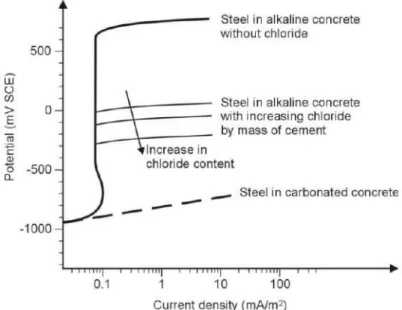
Figure 2.11 Schematic representation of the anodic polarization curve of steel in concrete with different chloride contents ... 22
Figure 2.12 Schematic representation of a cyclic anodic polarization curve of an active- passive material in a chloride-containing environment: pitting potential (Epit) and protection potential (Epro) are identified ... 24
Figure 2.13 Values of the pitting (Epit) and protection (Epro) potentials determined with tests on steel immersed in saturated solutions of calcium hydroxide (pH=12.6) at various levels of chlorides ... 24
Figure 2.14 Schematic representation of the influence of external anodic or cathodic polarization ... 25
Figure 2.15 Types of information obtainable from different electrochemical techniques .. 25
Figure 2.16 Schematic view of the electric field and current flow in an active/passive macrocell ... 26
Figure 2.17 Schematic representation of the measurement of potential of steel reinforcement ... 27
Figure 2.18 Correlation between potential and state of corrosion of carbon-steel reinforcement ... 28
xiv
Figure 2.19 Scheme of the Wenner technique to determine the electrical resistivity of concrete from the surface. Spacing of the electrodes shall be larger than the
maximum aggregate diameter ... 30
Figure 2.20 Positioning of Wenner probe electrodes on the concrete surface in order to stay as far as possible from the rebars after locating the reinforcement mesh ... 31
Figure 2.21 Polarization curve close to the corrosion potential ... 32
Figure 2.22 Illustration of linear polarization resistance measurements ... 33
Figure 2.23 On-site measurements of corrosion rate ... 34
Figure 2.24 Simplified representation of a corrosion cell of steel in concrete ... 39
Figure 2.25 Effect of cathodic diffusion on polarization ... 40
Figure 2.26 Effect of concrete resistance on polarization ... 41
Figure 2.27 Stage of the cathodic protection system ... 42
Figure 2.28 Cathodic protection system in ICCP ... 43
Figure 2.29 Reactions involved in the impressed current system ... 43
Figure 2.30 Electrochemical principle of the impressed current system ... 44
Figure 2.31 Cathodic protection system in SACP ... 46
Figure 2.32 Reactions involved in the sacrificial anode system ... 47
Figure 2.33 Electrochemical principle of the sacrificial system ... 47
Figure 2.34 Commercial type of sacrificial anodes ... 49
Figure 2.35 Polarization and depolarization scheme ... 52
Figure 3.1 Sacrificial anodes ... 63
Figure 3.2 Specimen design ... 64
Figure 3.3 Casting process by Rafdinal, 2016 ... 65
Figure 3.4 Measurement method of macro-cell corrosion current ... 66
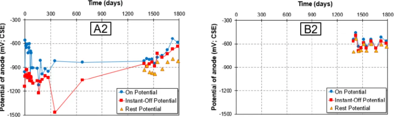
Figure 3.5 Protective current density of A1 and A2 ... 66
Figure 3.6 Protective current density of B1 and B2 ... 67
Figure 3.7 Macro-cell corrosion of steel bar protected by anode in A1 and A2 ... 67
Figure 3.8 Macro-cell corrosion of steel bar protected by anode in B1 and B2 ... 67
Figure 3.9 On potential of steel bar protected by sacrificial anode in A1 and A2 ... 69
Figure 3.10 On potential of steel bar protected by sacrificial anode in B1 and B2 ... 69 Figure 3.11 Instant-off potential of steel bar protected by sacrificial anode in A1 and A2 . 69 Figure 3.12 Instant-off potential of steel bar protected by sacrificial anode in B1 and B2 . 69
xv
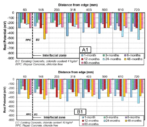
Figure 3.13 Rest potential of steel bar protected by sacrificial anode in A1 and B1 ... 70
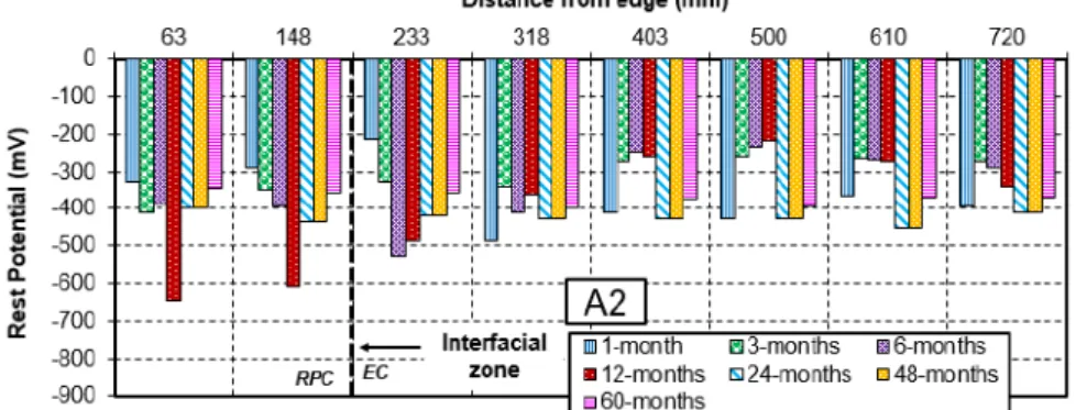
Figure 3.14 Rest potential of steel bar protected by sacrificial anode in A2 and B2 ... 70
Figure 3.15 Rest potential of steel bar without sacrificial anode in A1 ... 71
Figure 3.16 Rest potential of steel bar without sacrificial anode in A2 ... 71
Figure 3.17 Potential development of sacrificial anodes in A1 and B1 ... 71
Figure 3.18 Potential development of sacrificial anodes in A2 and B2 ... 72
Figure 3.19 Depolarization test value of A1 and B1 ... 73
Figure 3.20 Depolarization test value of A2 and B2 ... 73
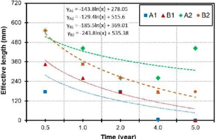
Figure 3.21 Effective length of sacrificial anode after five years of exposure ... 74
Figure 3.22 Sacrificial anode installed on the rebar ... 76
Figure 3.23 A 20-year-old deteriorated reinforcing bar ... 77
Figure 3.24 Specimen design ... 78
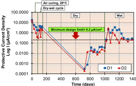
Figure 3.25 Protective current density ... 80
Figure 3.26 On potential of steel bar connected by sacrificial anode ... 81
Figure 3.27 Instant-off potential of steel bar connected by sacrificial anode ... 81
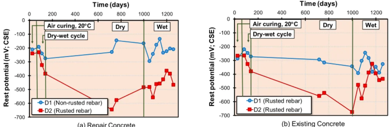
Figure 3.28 Rest potential of steel bar connected by sacrificial anode ... 81
Figure 3.29 Half-cell potential of steel bar without anode connection ... 82
Figure 3.30 Rest potential mapping of steel bar ... 82
Figure 3.31 Potential development of anodes ... 83
Figure 3.32 Depolarization test value of steel bar connected by sacrificial anodes ... 84
Figure 3.33 Specimen design ... 86
Figure 3.34 Sacrificial zinc anode F type ... 86
Figure 3.35 A 20-year-old deteriorated steel bar used in this study ... 87
Figure 3.36 Temperature change during the measurement process ... 88
Figure 3.37 The protective current of sacrificial anodes ... 89
Figure 3.38 Potential development of sacrificial anodes ... 90
Figure 3.39 On potential and instant-off potential of a steel bar with a sacrificial anode connection ... 91
Figure 3.40 Half-cell potential of steel bar without sacrificial anode connection ... 91
Figure 3.41 Corrosion potential of steel bar in chloride-free and chloride contaminated concrete ... 91
Figure 3.42 Depolarization test result ... 92
Figure 3.43 Relationship between corrosion potential and polarization resistance ... 92
xvi
Figure 3.44 Anodic polarization curve of sacrificial zinc anode ... 93
Figure 3.45 Anodic and cathodic polarization curve of rebar ... 93
Figure 3.46 Appearance of rebar corroded area in CL0-L and CL10-L ... 94
Figure 3.47 Corroded Area at 1003-days ... 94
Figure 3.48 Protective current density of sacrificial anodes in high temperature ... 95
Figure 3.49 Potential development of sacrificial anode, (a) on potential, (b) instant-off potential, (c) rest potential ... 95
Figure 3.50 Rest potential of half-cell potential of steel bar without anode connection ... 96
Figure 3.51 Potential development of steel bar connected by the anode ... 96
Figure 3.52 Depolarization test value ... 97
Figure 3.53 Crack appearance in the side part of specimens ... 97
Figure 3.54 Cross-sectional area of the specimen with 10kg/m3 of chloride content ... 98
Figure 3.55 Specimen design ... 100
Figure 3.56 Protective current density ... 100
Figure 3.57 Fluorescence microscopic of sacrificial anodes boundary in 50µm scale ... 101
Figure 3.58 Sacrificial anode installed on the rebar ... 101
Figure 3.59 Detail of specimens ... 102
Figure 3.60 Protective current density ... 103
Figure 3.61 Potential development of steel bar ... 104
Figure 3.62 Depolarization test of steel bar ... 104
Figure 3.63 Anodic-cathodic polarization curve of steel bar ... 105
Figure 3.64 Anodic polarization curve of sacrificial anodes ... 105
Figure 4.1 Detail of RC beams ... 111
Figure 4.2 Exposure condition ... 112
Figure 4.3 Measurement point of non-destructive test ... 112
Figure 4.4 Test result Ultrasonic Pulse Velocity (UPV) ... 113
Figure 4.5 Test result of rebound hammer test ... 113
Figure 4.6 Defective appearance in RC-1 after 41-years ... 114
Figure 4.7 Defective appearance in RC-2 after 41-years ... 114
Figure 4.8 Appearance and cracking pattern of RC-1 ... 115
Figure 4.9 Appearance and cracking pattern of RC-2 ... 115
Figure 4.10 Appearance and cracking pattern of RC-3 ... 116
Figure 4.11 Appearance and cracking pattern of RC-4 ... 116
xvii
Figure 4.12 Appearance and cracking pattern of RC-5 ... 117
Figure 4.13 Corrosion map of RC-1 ... 118
Figure 4.14 Corrosion map of RC-2 ... 118
Figure 4.15 Corrosion map of RC-3 ... 118
Figure 4.16 Corrosion map of RC-4 ... 118
Figure 4.17 Corrosion map of RC-5 ... 119
Figure 4.18 Sampling position of chloride ion profile test ... 119
Figure 4.19 Chloride ion profile of specimens ... 120
Figure 4.20 Repair design of the specimens ... 122
Figure 4.21 Material for repair process ... 123
Figure 4.22 Repair process in patch repair concrete ... 124
Figure 4.23 Repair process in non-patch repair concrete ... 124
Figure 4.24 Current flow measurement method ... 125
Figure 4.25 Measurement scheme of sacrificial anode potential ... 125
Figure 4.26 Measurement scheme of steel bar potential ... 125
Figure 4.27 Schematic method of depolarization test ... 126
Figure 4.28 Schematic measurement of polarization resistance ... 126
Figure 4.29 Schematic measurement setting of anodic-cathodic polarization curve test .. 127
Figure 4.30 Anode setting position in RC-1 ... 128
Figure 4.31 Anode setting position in RC-2 ... 128
Figure 4.32 Protective current density of anodes in Stage I of repair ... 129
Figure 4.33 Current flow of cylindrical ribbed-sacrificial anodes in Stage III of repair ... 129
Figure 4.34 Current flow of rectangular sacrificial anodes in Stage III of repair ... 130
Figure 4.35 Protective current density in Stage III of repair ... 130
Figure 4.36 Instant off potential development of sacrificial anodes in non-patch repair .. 131
Figure 4.37 Instant off potential development of sacrificial anodes in non-patch repair .. 131
Figure 4.38 Anodic polarization curve of anodes in patch repair of RC-1 ... 132
Figure 4.39 Anodic polarization curve of anodes in non-patch repair of RC-1 ... 133
Figure 4.40 Anodic polarization curve of anodes in patch repair of RC-2 ... 133
Figure 4.41 Anodic polarization curve of anodes in non-patch repair of RC-2 ... 133
Figure 4.42 Potential development of tensile steel bar in RC-1 during Stage I of repair .. 134
Figure 4.43 Potential development of tensile steel bar in RC-2 during Stage I of repair .. 135
xviii
Figure 4.44 Rest potential of tensile steel bar of RC-1 and RC-2 during Stage II of repair ... 136 Figure 4.45 Potential development of tensile steel bar in RC-1 during Stage III of repair
... 136 Figure 4.46 Potential development of tensile steel bar in RC-2 during Stage III of repair
... 137 Figure 4.47 Rest potential development of RC-1 and RC-2 ... 139 Figure 4.48 Depolarization development of RC-1 and RC-2 ... 142 Figure 4.49 Anodic-cathodic polarization of tensile steel bar in RC-1 during Stage III of
repair process ... 143 Figure 4.50 Anodic-cathodic polarization of compressive steel bar in RC-1 during Stage
III of repair process ... 143 Figure 4.51 Anodic-cathodic polarization of tensile steel bar in RC-2 during Stage III of
repair process ... 144 Figure 4.52 Anodic-cathodic polarization of compressive steel bar in RC-2 during Stage
III of repair process ... 144 Figure 4.53 Polarization resistance of tensile steel bar in RC-1 and RC-2 ... 145 Figure 4.54 Corrosion current density of tensile steel bar in RC-1 and RC-2 ... 146 Figure 4.55 Cumulative anodes charges of RC-1 and RC-2 ... 146 Figure 4.56 Effect of repair to the deterioration progress and performance degradation .. 148 Figure 4.57 Crack formation of RC-1 after two-years of repair ... 149 Figure 4.58 New crack formation in patch repair area of RC-1 ... 149 Figure 4.59 Crack formation o RC-2 after two-years of repair ... 150 Figure 4.60 New crack formation in patch repair area of RC-2 ... 150 Figure 4.61 Rebar condition in the middle tensile area of (a) RC-3 and (b) RC-4 ... 152 Figure 4.62 Current flow of sacrificial anodes in RC-3 and RC-4 ... 153 Figure 4.63 Protective current density of sacrificial anodes in RC 3 and 4 ... 154 Figure 4.64 Instant-off potential of sacrificial anodes in RC-3 and RC-4 ... 154 Figure 4.65 Anodic polarization curve of sacrificial anodes in RC-3 ... 155 Figure 4.66 Anodic polarization curve of sacrificial anodes in RC-4 ... 155 Figure 4.67 Potential development of tensile steel bar in RC-3 ... 157 Figure 4.68 Potential development of tensile steel bar in RC-4 ... 157 Figure 4.69 Corrosion map development of RC-3 during repair process ... 158
xix
Figure 4.70 Corrosion map development of RC-4 during repair process ... 159 Figure 4.71 Depolarization map development of RC-3 during repair process ... 160 Figure 4.72 Depolarization map development of RC-4 during repair process ... 161 Figure 4.73 Anodic-cathodic polarization of tensile steel bar in RC-3 ... 162 Figure 4.74 Anodic-cathodic polarization of compressive steel bar in RC-3 ... 163 Figure 4.75 Anodic-cathodic polarization of tensile steel bar in RC-4 ... 163 Figure 4.76 Anodic-cathodic polarization of compressive steel bar in RC-4 ... 164 Figure 4.77 Polarization resistance of tensile steel bar in RC-3 and RC-4 ... 164 Figure 4.78 Corrosion current density of tensile steel bar in RC-3 and RC-4 ... 165 Figure 4.79 Cumulative anodes charges of RC3 and RC-4 ... 165 Figure 4.80 Effect of repair to the deterioration progress and performance degradation
in RC-3 and RC-4 ... 167 Figure 4.81 Crack formation of RC-3 after two years of repair ... 167 Figure 4.82 New crack formation in patch repair area of RC-3 ... 168 Figure 4.83 Crack formation of RC-4 after two years of repair ... 168 Figure 4.84 New crack formation in patch repair area of RC-4 ... 168 Figure 4.85 Sacrificial anodes setting position ... 171 Figure 4.86 Connection pattern of sacrificial anodes and steel bar ... 171 Figure 4.87 Current flow of sacrificial anodes ... 172 Figure 4.88 Potential development of tensile steel bar ... 173 Figure 4.89 Depolarization map ... 174 Figure 4.90 Steel bar condition change time dependently ... 175 Figure 4.91 Correlation of depolarization to steel bar condition in non-patch repair at
400 mm from edges ... 176 Figure 4.92 Correlation of depolarization to steel bar condition in patch repair at 1200
mm from edges (middle span) ... 176 Figure 5.1 Schematic of embeddable titanium wire sensor (TWS) ... 183 Figure 5.2 Potential measurement of titanium wire sensor ... 183 Figure 5.3 Potential of titanium wire sensor and temperature coefficient ... 184 Figure 5.4 Potential of steel bar vs. Titanium wire sensor and SSE ... 184 Figure 5.5 Titanium wire sensor (TWS) setting position in RC-1 and RC-2 ... 185 Figure 5.6 Titanium wire sensor position in the cross-sectional area of non-patch repair
... 186
xx
Figure 5.7 Measurement position of SCE in RC-1 and RC-2 ... 186 Figure 5.8 Potential development of titanium wire sensor (TWS) vs. CSE, 25°C in RC-
1 and RC-2 ... 187 Figure 5.9 On potential of steel bar coincides TWS position vs. TWS and SCE in RC-1
... 188 Figure 5.10 Instant-off potential of steel bar coincides TWS position vs. TWS and SCE
in RC-1 ... 188 Figure 5.11 Rest potential of steel bar coincides TWS position vs. TWS and SCE in RC-
1 ... 188 Figure 5.12 Depolarization test value of steel bar coincides TWS position vs. TWS and
SCE in RC-1 ... 188 Figure 5.13 On potential of steel bar coincides TWS position vs. TWS and SCE in RC-
2 ... 189 Figure 5.14 Instant-off potential of steel bar coincides TWS position vs. TWS and SCE
in RC-2 ... 189 Figure 5.15 Rest potential of steel bar coincides TWS position vs. TWS and SCE in RC-
2 ... 189 Figure 5.16 Depolarization test value of steel bar coincides TWS position vs. TWS and
SCE in RC-2 ... 190 Figure 5.17 Titanium wire sensor (TWS) setting position in RC-3 and RC-4 ... 191 Figure 5.18 Titanium wire sensor position in the cross-sectional area of patch and non-
patch repair ... 192 Figure 5.19 Materials for repair: (a) polymer modified mortar, (b) coating agent, (c)
cylindrical ribbed sacrificial zinc anode and (d) Cementitious anode coating material mixed with LiOH ... 192 Figure 5.20 Reference electrode: (a) titanium wire sensor (TWS) and (b) saturated
calomel electrode (SCE) ... 192 Figure 5.21 The installation process of titanium wire sensor in concrete ... 192 Figure 5.22 Measurement position of SCE in RC-3 and RC-4 ... 193 Figure 5.23 Potential development of titanium wire sensor (TWS) vs. CSE, 25°C in RC-
3 and RC-4 ... 194 Figure 5.24 On potential of steel bar coincides TWS position vs. TWS and SCE in RC-
3 ... 195
xxi
Figure 5.25 Instant-off potential of steel bar coincides TWS position vs. TWS and SCE in RC-3 ... 196 Figure 5.26 Figure 5.26 Rest potential of steel bar coincides TWS position vs. TWS and
SCE in RC-3 ... 196 Figure 5.27 Depolarization of steel bar coincides TWS position vs. TWS and SCE in
RC-3 ... 197 Figure 5.28 On potential of steel bar coincides TWS position vs. TWS and SCE in RC-
4 ... 197 Figure 5.29 Instant-off potential of steel bar coincides TWS position vs. TWS and SCE
in RC-4 ... 198 Figure 5.30 Rest potential of steel bar coincides TWS position vs. TWS and SCE in RC-
4 ... 198 Figure 5.31 Depolarization test value of steel bar coincides TWS position vs. TWS and
SCE in RC-4 ... 199 Figure 5.32 Potential of TWS vs. current density of sacrificial anodes in RC-1 ... 200 Figure 5.33 Potential of TWS vs. current density of sacrificial anodes in RC-2 ... 200 Figure 5.34 Potential of TWS vs. current density of sacrificial anodes in RC-3 ... 200 Figure 5.35 Potential of TWS vs. current density of sacrificial anodes in RC-4 ... 200 Figure 5.36 Polarization curve of titanium wire sensor (TWS) in RC-3 ... 201 Figure 6.1 Corrosion regions of concrete structure in marine environments ... 206
xxii
1
1. CHAPTER I
General Introduction
1.1 Background of study
Reinforced concrete (RC) has been one of the most utilized materials in the construction sector, especially in the construction of bridges, ports, buildings, tunnels, and skyscrapers (Shi et al., 2012; Aguirre-Guerrero and Guiérrez, 2018). Nowadays, RC is an ideal construction material due to the characteristic of composite material with the amalgamation of the high compressive strength of Portland cement concrete and the high tensile strength of steel bar (Bertolini et al., 2004). The environment variety that RC structures are exposed to make it necessary to consider the durability of the concrete as an additional property to the mechanical strength because the service life of the structure depends on its durability (Neville, 2001).
The main problem of RC’s durability is the corrosion of the steel bar, which diminishes the mechanical and structural properties (Bertolini et al., 2004). The aggressive exposure environments mainly cause the corrosion of the steel bar, mostly the existence of chloride ions and/or carbonation (Ahmad, 2003). Non-carbonated concrete is defined as high alkalinity material with a pH between 12.6 and 13.6 (Alonso and Andrade, 1987). Under these pH conditions, the steel bar spontaneously forms a passive protective layer. The aggressive agents such as chloride ions and/or carbon dioxide can destroy this layer, which results in de-passivation (Bertolini et al., 2004; Fajardo et al., 2009). Chloride attack is one of the most aggressive causes that leads to corrosion of the steel bar. In this case, the chloride ions are spread through the concrete until they reach the steel surface, where they accumulate and reach a critical concentration. This chloride accumulation destroys the passive layer of the steel bar and begins the corrosive process (Angst et al., 2009). Carbonation is a process in which carbon dioxide from the environment enters concrete. It decreases the alkalinity of concrete by reducing the pH to approximately 9. Therefore, the passive layer is destablished, which causes corrosion in the steel bar (Baccay et al., 2006; Han et al., 2013).
RC structures in the marine environment are particularly subjected to chloride-induced corrosion. Problems develop when the chloride-ion penetrates into concrete and reaches the steel bar surface. Steel bar, which is normally in a passive state due to the high alkalinity of
2
concrete, loses passivity and begins to corrode when a threshold level of chloride-ion concentration is exceeded (West and Hime, 1985). The corrosion products can occupy several times the original volume of steel bar, causing tensile forces to develop in concrete.
These stresses lead to cracking of the concrete cover, delamination, spalling, and further corrosion damage to the structure (Steven, 2003).
Some of the countermeasures developed to stop chloride induced-corrosion focus on the reinforcement itself and other techniques to control corrosion by reducing the porosity of the concrete cover. The further corrosion damage also can be controlled by isolating the structure from the environment through surface protection treatments or by altering the kinetics of the reactions or electrochemical potential of the affected metals (Navarro, 2018).
Several ways of the corrosion mitigation procedure on RC structures in marine environment are existed such as cathodic protection, coating, corrosion inhibitor, desalination, electrochemical realkalization (ER), and electrochemical chloride extraction (ECE) (Bertolini et al., 2004; Cardenas et al., 2010; Karthick et al., 2016; Kupwade-Patil et al., 2012; Pan et al., 2008). Among these methods, cathodic protection (CP) is the oldest, and it has been widely used in steel structures submerged in water. The application of CP in concrete began around 1955 for submerged and buried structures. Since the mid-1970s, cathodic protection has been used in RC structures such as buildings, bridged, tunnel, etc.
Therefore, CP is the standardized electrochemical technique in some countries (Martínez et al., 2009). The general principle of CP is a corrosion mitigation method that imposes an external voltage on the steel bar surface, which forces the steel bar to become cathodic, thereby mitigating corrosion. Both impressed current (active systems) and galvanic or sacrificial anode (passive systems) are used. CP is still considered one of the only technologies that have proven to stop corrosion of steel bar, regardless of the chloride-ion contamination in concrete (Daily, 2003).
During the application of CP especially sacrificial anodes, patch repairs are sometimes necessary to remove of all cracked and delaminated concrete, cleaning of all corroded steel bar, application of the protective coating on the embedded steel bars, and repairing with new mortar material or micro concrete (Ali et al., 2018). Patch repair has limited success against chloride-induced corrosion because of the surrounding chloride-contaminated concrete; as a result, the steel bar continues to remain susceptible to corrosion (Morgan, 1996; Miyagawa, 1991). The patched area of new repair material often causes the formation of incipient anodes or macro-cell corrosion adjacent to the repairs (Ali et al., 2018).
3
There are a few crucial factors, which should be considered in selecting a suitable durable repair strategy, such as the level of deterioration, specific condition of structures, and the environmental condition (Morgan, 1996; ACI 546R, 2014; ACI 562M, 2016).
1.2 Research objective and limitation
The objective of this study is to find a suitable repair strategy on naturally damaged RC beam structures by sacrificial anodes cathodic protection. Several considerations of utilization sacrificial anodes in repair structures were demonstrated in laboratory cases such as temperature effects, steel surface condition, the ability of sacrificial anodes to mitigate macro-cell corrosion, and an attempt to decrease the high consumption of sacrificial anodes in the early stage of repair. Further, the application of several repair methods on 44-years naturally damaged RC beams structures using sacrificial anodes, patch repair, and corrosion inhibitor were presented as a field case. In addition, a new corrosion monitoring device made of titanium probe iridium-enriched mixed with metal oxide was used as a new sensor in repair strategy. The repair and maintenance procedures based on laboratory and field applications were presented in the last part of this study. The limitation of this study is that the deterioration of RC structures results from chloride-induced corrosion. The observation of corrosion monitoring sensor is limited only in the repaired RC members.
1.3 Research contribution and standing point
This study completes an evaluation of the repair methods of serious corrosion damaged RC beam structures, specifically using sacrificial anodes cathodic protection on 44-years naturally damage RC beam structures. This result is necessary for the maintenance procedure of actually damaged structures in the marine or aggressive environment during the service life.
1.4 Dissertation arrangement
Figure 1.1 illustrated the dissertation arrangement which is composed of seven chapters as follows.
Chapter 1 describes the background of this study, research objectives, limitations, research contribution, and standing point.
Chapter 2 discusses the literature review related to corrosion and corrosion protection method by cathodic protection in RC structures at the current situation and the issues to be addressed in this research.
4
Chapter 3 demonstrates the fundamental study and discussion of the effectiveness of sacrificial anodes cathodic protection on RC structures in laboratory cases. Some considerations during the application of sacrificial anodes cathodic protection such as the effect of the rust removal process on steel bar surface before repair, the influence of high and low temperature, and the occurrence of macro-cell corrosion in repair RC member are presented. The method of reducing the high current consumption of sacrificial anodes in the early stage is also reviewed.
Chapter 4 presents the field case demonstration on repair strategy of 44-years naturally damaged RC beams using sacrificial anodes cathodic protection.
Chapter 5 contains the utilization of a new embeddable corrosion monitoring sensor in repaired RC member.
Chapter 6 formulates the design and maintenance procedure of repair method by sacrificial anodes cathodic protection applied to RC structures based on Chapter 4 and Chapter 5.
Chapter 7 summarizes the results obtained from Chapter 3 to Chapter 6. Some future research works were recommended based on the results.
Figure 1.1 Flowchart of dissertation arrangement Chapter 1. General introduction
Chapter 2. State of the art on repair strategy by sacrificial anodes cathodic protection in RC structures
Chapter 5. Utilization of new embeddable corrosion monitoring
sensor in repaired RC members Chapter 3.Fundamental study on the effectiveness
of sacrificial anodes in repaired RC member
Chapter 4. Repair method of severely damaged RC beams by using sacrificial anode cathodic protection
Chapter 7. Conclusions and future works
Chapter 6. Design, monitoring, and maintenance of repair method by sacrificial anodes cathodic protection in RC structures
5 1.5 References
ACI 546R-14, 2014. “Guide to Concrete Repair”, in American Concrete Institute (ACI) Committee 546. Farmington Hills, MI.
ACI 562M-16, 2016. “Code requirements for assessment, repair and rehabilitation of existing concrete structures and commentary”, American Concrete Institute (ACI) Commitee 562. Farmington Hills, MI.
Ahmad, S., 2003. “Reinforcement corrosion in concrete structures, its monitoring and service life prediction - a review”. Cem. Concr. Compos. Vol. 25 (4-5), 459-471.
Aguirre-Guerrero, A. M, Guiérrez, R. M., 2018, “Eco-efficient Repair and Rehabilitation of Concrete Infrastructures: Part 13 - Assessment of corrosion protection methods for reinforced”, Woodhead Publishing Series in Civil and Structural Engineering, pp. 315- 353.
Ali, M. S., Leyne, E., Saifuzzaman, M., Mirza, M. S., 2018. “An experimental study of electrochemical incompatibility between repaired patch concrete and existing concrete”. Construction and Building Materials, Vol. 174, pp. 159-172.
Alonso, C., Andrade, C., 1987. “Corrosion behavior of steel during accelerated carbonation of solutions which simulate the pore concrete solution”. Materiales de construccio´n.
37 (206), 5-16.
Angst, U., Elsener, B., Larsen, C.K., Vennesland, Ø., 2009. “Critical chloride content in reinforced concrete—a review”, Cem. Concr. Res. Vol. 39, No. 12, pp. 1122-1138.
Baccay, M.A., Otsuki, N., Nishida, T., Maruyama, S., 2006. “Influence of cement type and temperature on the rate of corrosion of steel in concrete exposed to carbonation”, Corrosion, Vol. 62, No. 9, pp. 811-821.
Bertolini, L., Elsener, B., Pedeferri, P., Polder, P., 2004. “Corrosion of Steel in Concrete:
Prevention, Diagnosis, Repair”, Wiley-VCH Verlag GmbH & Co. KGaA, Weinheim.
Cardenas, H., Kupwade-Patil, K., Eklund, S., 2010. “Corrosion mitigation in mature reinforced concrete using nanoscale pozzolan deposition”, J. Mater. Civil En, Vol. 23, No. 6, 752-760.
Daily, S. F., 2003. “Galvanic cathodic protection of reinforced and prestressed concrete using thermally sprayed aluminium coating”, Concrete Repair Bulletin, July/August 2003.
Karthick, S.P., Madhavamayandi, A., Muralidharan, S., Saraswathy, V., 2016.
“Electrochemical process to improve the durability of concrete structures”, J. Build.
Eng. Vol. 7, pp. 273-280.
Kupwade-Patil, K., Cardenas, H.E., Gordon, K., Lee, L.S., 2012. “Corrosion mitigation in reinforced concrete beams via nanoparticle treatment”, ACI Mater. J. Vol. 109, No. 6.
Fajardo, G., Valdez, P., Pacheco, J., 2009. “Corrosion of steel rebar embedded in natural pozzolan based mortars exposed to chlorides”, Constr. Build. Mater. Vol. 23, No. 2, pp. 768-774.
Han, S.-H., Park, W.-S., Yang, E.-I., 2013. “Evaluation of concrete durability due to carbonation in harbor concrete structures”, Constr. Build. Mater. Vol. 48, pp.
1045-1049.
Martínez, I., Andrade, C., Castellote, M., de Viedma, G.P., 2009. “Advancements in nondestructive control of efficiency of electrochemical repair techniques”, Corros.
Eng., Sci. Technol. Vol. 44, No. 2, pp. 108-118.
6
Morgan, D. R., 1996. “Compatibility of concrete repair materials and systems”, Construction and Building Materials, Vol. 10, No. 1, pp. 57-67.
T. Miyagawa, 1991. “Durability design and repair of concrete structures: chloride corrosion of reinforcing steel and alkali-aggregate reaction”, Mag. Concr. Res. Vol. 43, No. 156, pp. 155–170.
Navarro, I. J., Yepes, V., and Marti, J. V., 2018, “Life cycle cost assessment of preventive strategies applied to prestressed concrete bridges exposed to chlorides”, Sustainability, 10, 845.
Neville, A., 2001. “Consideration of durability of concrete structures: past, present, and future”, Mater. Struct. Vol. 34, No. 2, pp. 114-118.
Pan, T., Nguyen, T., Shi, X., 2008. “Assessment of electrical injection of corrosion inhibitor for corrosion protection of reinforced concrete”, Transp. Res. Rec. J. Transp. Res.
Board. Vol. 2044, pp. 51-60.
Shi, X., Xie, N., Fortune, K., Gong, J., 2012. “Durability of steel reinforced concrete in chloride environments: an overview”, Constr. Build. Mater. Vol. 30, 125-138.
Steven, F. D., 2003, “Galvanic cathodic protection of reinforced and prestressed concrete using a thermally sprayed aluminum coating”, Concrete Repair Bulletin, July/August 2003.
West, R. E and Hime, W. G., 1985, “Chloride profiles in salty concrete”, Materials Performance, vol. 24, pp. 29-36.
7
2. CHAPTER II
State of the art on repair strategy by sacrificial anodes cathodic protection in RC structures
2.1 Introduction
In this chapter, several kinds of literature regarding deterioration and repair strategy of corrosion damaged RC structures are reviewed. The detailed information of the cathodic protection system from the previous researcher is presented as well. The application of cathodic protection in concrete from some experienced countries was shown. In addition, the present issues that address in this study are discussed in the last part of this chapter. The organization of content in this chapter is summarized as follows.
Section Title
2.2 Durability of RC structures 2.2.1 Corrosion mechanism 2.2.2 Chloride-induced corrosion 2.2.3 Form of corrosion
2.2.4 Electrochemical aspects of corrosion in concrete 2.3 Corrosion inspection, assessment, and monitoring
2.3.1 Half-cell potential 2.3.2 Resistivity of concrete 2.3.3 Corrosion rate
2.3.4 Chloride determination 2.3.5 Corrosion monitoring
2.4 Repair method of chloride-induced corrosion damaged RC structures by cathodic protection
2.4.1 Impressed current cathodic protection (ICCP) 2.4.2 Sacrificial anode cathodic protection (SACP)
2.4.3 Performance criteria of cathodic protection in concrete 2.5 Summary of problems to be solved
2.2 Durability of RC structures
Durability of RC structures in the marine environment depends on the deterioration of concrete and the steel bar corrosion (Okada, 1976). Further, the corrosion affected by two phenomena either cracked on concrete surface or chloride penetration. Both crack and chloride could exist even from the beginning or even during service life. These two problems are related to each other. When the reinforcing steel rusts, the corrosion products generally occupy considerably more volume than that of the original steel (CEB, 1989). It promotes
8
the internal pressure inside the concrete and initiates the concrete cover cracked and spalled.
As a result, the rate of corrosion is accelerated.
One of the most common causal factors of reinforcement corrosion is the ingress of chloride ions through the concrete pore network when the concrete is located in marine environments. Chloride ions cause localized corrosion of the reinforcement and, therefore, produce premature and unexpected structural failure. Chloride penetration may occur either by diffusion from water-saturated concrete or due to absorption/desorption phenomena throughout the wet/dry cycle in tidal or splash zone exposure. These cycles produce faster chloride ion ingress mechanisms because, besides diffusion, capillary absorption or saline mist phenomena also induce higher moisture diffusivity. Chloride penetrating through concrete cover to steel bar breaks the passivation of reinforcement to initiate corrosion.
The deterioration progress of RC structures from chloride attack involves the initiation, propagation, acceleration, and deterioration stages (JSCE, 2007), as shown in Figure 2.1. In each stage, the deterioration has different influences on the RC member. The degree of deterioration progress with performance degradation also varies according to the performance attribute under investigation.
Figure 2.1 Deterioration progress of chloride attack in RC structures
9 2.2.1 Corrosion mechanism
A highly alkaline pore solution in concrete with pH between 12.6 and 13.6, principally of sodium and potassium hydroxides, is formed during the hydration process of cement in concrete (Bertolini et al., 2004). The thermodynamically stable compounds of iron are iron oxides and oxyhydroxides in this environment. A thin protective oxide film (the passive film) is formed spontaneously on ordinary steel bars embedded in alkaline concrete (Stratfull, 1957; Stratfull, 1974; Pedeferry, 1965). The passive film is only consisted of a few nanometers thick and is composed of more or less hydrated ion oxides with varying degree of Fe2+ and Fe3+ (Page, 1997). The passive film protects and immune to mechanical Table 2.1 and Table 2.2 present the definition and criteria for the diagnosis of deterioration degree (JSCE, 2007).
Table 2.1 Definition of deterioration stages due to chloride attack (JSCE, 2007)
Stage of
deterioration Definition Stage determined by
Initiation Until the chloride ion concentration on the surface of the steel reaches the marginal concentration for the occurrence of corrosion (standard value is 1.2 kg/m3).
Diffusion of chloride ions Initially contained chloride ion concentration.
Propagation From the initiation of steel corrosion until cracking due to corrosion.
Rate of steel corrosion.
Acceleration Stage in which steel corrodes at a high
rate due to cracking due to corrosion. Rate of corrosion of steel with cracks.
Deterioration Stage in which load-bearing capacity is reduced considerably due to the increase of corrosion amount.
Table 2.2 Criteria for diagnosis of deterioration degree (JSCE, 2007)
Evaluation
Items Deterioration Degree
0 1 2 3 4 5
Corrosion
of steel bar None Rust spots found on the concrete surface
Partial rust stains found on the concrete surface
Significant
rust staining Significant
floating rust A dramatic increase in the amount of floating rust Cracking None Partial
cracks found on the concrete surface
Some cracks Many cracks, including some of several mm or more in width
Many cracks of several mm in width
-
Spalling covering concrete
None None Partial floating concrete found
Partial
spalling found Significant
spalling Drastic spalling
10
damage of the steel surface, and it can be destroyed by carbonation of concrete or by the existence of chloride ions, then the steel bar is depassivated (Bertolini et al., 1998).
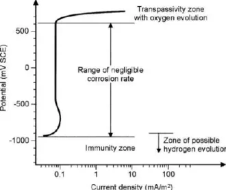
The stability of iron metal as a function of potential and pH called the Pourbaix diagram is presented in Figure 2.2. The region of immunity shown in the Pourbaix diagram for Fe-H2O reveals that the corrosion cannot occur in this region. For instance, at a point X in the diagram as the activity of Fe2+ would be very low (~10-10). As iron is transformed into soluble species in the corrosion region, it is expected that iron would corrode. An oxide species in contact with an aqueous solution along a boundary will not allow corrosion to proceed if it is impervious and highly adherent. The thin layer of oxide on the metal surface, such as Fe3O2 or Fe3O4, is highly protected under the above condition. Metals like steel are known to resist corrosion because of the development of oxide films in the air (Ahmad, 2006).
Figure 2.2 Potential-pH diagram for iron (Ahmad, 2006)
Corrosion in concrete is the process in which iron at the anode and oxygen is reduced at the cathode, with the electrons flowing in the steel surface between anode and cathode. The electrolyte is the alkaline pore solution while the steel bar serves as the metallic path between the anode and cathode in RC members. The anodes and cathodes are formed on the steel surface are depicted in Figure 2.3. The anodic reaction leads to the iron cations formation
11
is shown in Equation 2.1, and Equation 2.2 presents the cathodic reaction, which balances the anodic reaction by oxygen reduction with hydroxyl anions production.
Anodic reaction: Fe → Fe2+ + 2e- (2.1)
Cathodic reaction : ½O2 + H2O + 2e- → 2OH- (2.2)
In the RC structures case, the stability of the passive film on the steel bar was built from the combination of the products of the anodic and the cathodic reaction. Oxygen availability and the pH value in the interface of steel bar/concrete are the main factors of the stability of this passive film (Rincón et al., 2008). Steel bar embedded in concrete is naturally protected against corrosion by the high alkalinity of the cement pore solution (pH > 12.5) and by the barrier effect of the concrete cover, which limits the oxygen and moisture required for active corrosion. The high pH suppresses steel corrosion by permitting the formation of a very thin (1-10 nm thick) passivating ferric oxide film (γ-Fe2O3) on the steel surface (Richardson, 2002). Either a reduction in alkalinity (typically in carbonated concrete) or by chloride ingress in the marine environment can be disrupted or de-passivated the passive layer on the steel. Depassivation renders the steel thermodynamically liable to corrode; whether it does so depend primarily on the availability of moisture and oxygen at the cathode.
Figure 2.3 A schematic illustration of the corrosion process in concrete
In the presence of chloride ions, oxygen, and water in concrete, they may act as a catalyst by introducing additional anodic reactions are represented in Equation 2.3.
Fe + 3Cl! ® FeCl"!+ 2e!
Followed by FeCl"!+ 2OH! ® Fe(OH)# + 3Cl! or
Fe + 4Cl! ® FeCl$#!+ 2e!
Followed by FeCl$!+ 2OH! ® Fe(OH)#+ 4Cl!
12 or
Fe + 6Cl! ® FeCl""!+ 3e!
followed by FeCl""!+ 2OH! ® Fe(OH)# + 6Cl! (2.3)
These reactions remove ferrous of ferric ions from the steel by forming complex ions with the chlorides then deposited near the anode where they join with hydroxyl ions to form various corrosion products. The chloride ions are released to repeat the process. Secondary reactions may occur due to the expansive products of corrosion. Although the Fe#% and OH! ions both diffuse into the concrete (from anode to cathode, respectively), the corrosion products formed near the anode because of the OH! ions are smaller and more diffuse through the concrete more readily (Bertolini, 2013). If the supply of oxygen is restricted, ferrous oxides and hydroxides form (Equation 2.4 and Figure 2.3) as follows.
Fe#%+ 2(OH)!® Fe(OH)# or
Fe#%+ 2(OH)! ® FeO + H#O (2.4)
If the oxygen is available, ferric oxides and hydroxides form (Equation 2.5) (Christodoulou, 2008; Bertolini, 2013).
2Fe(OH)#+&
#O# ® Fe# . H#O + H#O (red rust) or 2Fe(OH)#+&#O#+ H#O ® 2Fe(OH)" (red rust) or 3Fe(OH)#+&#O# ® Fe"O$+ 3H#O (black rust) or 2FeO +&#O#+ H#O ® Fe#O". H#O (red rust)
or 2FeO +&
#O#+ 3H#O ® 2Fe(OH)" (red rust)
or 3FeO +&#O# ® Fe#O$ (black rust) (2.5)
The preceding chemical reactions show the transformation of steel from ferrous hydroxides (Fe(OH)2), which will react with oxygen and water to produce ferric hydroxides (Fe(OH)3), and the last component, which is the hydrated ferric oxide (rust); its chemical term is Fe2O3.H2O. Ferric hydroxide has more effect on concrete deterioration and spalling of concrete cover as its volume will increase the volume of the original steel bars by about two times or more. When iron goes to hydrated ferric oxides in the presence of water, its
13
volume will increase more to reach about six times its original volume and will become soft.
In this stage, cracks on concrete start until the concrete cover falls; rust, with its brown color, can be seen on the steel bar. Iron (Fe) that has been converted to Fe2+ can produce the corrosion products of hydroxides, oxides, and oxide-hydroxides, depending on conditions of temperature, atmospheric pressure, potential, and pH. These corrosion products occupy larger volumes than the original iron, as shown in Figure 2.4. The expansion volume of these corrosion products causes cracking and spalling in the concrete cover.
Figure 2.4 Relative volume of iron corrosion product (Liu, 1996) 2.2.2 Chloride-induced corrosion
Chloride-induced corrosion is a frequent cause of steel bar corrosion (Arup, 1983). The recent standard design codes for reinforced concrete structures impose restrictions on the amount of chloride that may be introduced from raw materials containing significant amounts of chlorides. According to European standard EN 206, the maximum allowable chloride contents are 0.2%-0.4% chloride ions by mass of binder (Bertolini, 2004). These restrictions are aimed to reduce the corrosion risk due to chloride in the fresh concrete mix.
In some RC structures in the past, chlorides have been unknowingly added to the concrete mix, through contaminated mixing water, aggregates (sea gravel or sands without washing them with chloride-free water) or admixtures (calcium chlorides, which is now prohibited, in the past was the most common accelerating admixture). The other chloride source in concrete is penetration from the environment in the marine environment in a road structure in the regions where chloride-bearing de-icing salts are used in wintertime (Bertolini, 2004).
Corrosion of steel bar in non-carbonated concrete can only take place once the chloride contamination in concrete in contact with the steel surface has reached a threshold value.
This threshold value depends on several parameters; however, the electrochemical potential of the steel bar, which is related to the amount of oxygen that can reach the steel surface, has a major influence. Relatively low levels of chlorides are sufficient to initiate corrosion in