Switching of Phase Differences in Coupled Chaotic Circuits with Regular Tetrahedron Form
Takahiro Nagai, Yoko Uwate and Yoshifumi Nishio (Tokushima University)
1. Introduction
Coupled chaotic systems are suitable models to ex- press many kinds of high-dimensional nonlinear phe- nomena. In [1], coupled chaotic circuits have produced anti-phase synchronization or chaotic synchronization.
In this study, we investigate synchronization phenom- ena in coupled chaotic circuits with regular tetrahedron form.
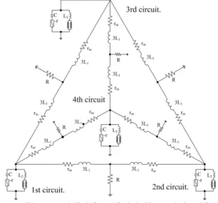
2. Circuit Model
We show the circuit diagram of coupled chaotic cir- cuits in Fig. 1. Each chaotic circuit is composed of two inductors, a capacitor, a negative resistor and diodes.
We couple chaotic circuits via L1 and ground by cou- pling resistorRin this study. In the computer simula- tions, we assume that thevd−ik characteristics of the nonlinear resistor are given by diodes.
Figure 1: Circuit model in tetrahedron form.
The normalized circuit equations are expressed as:
dxak dτ =1
3
{
(xak+xbk+xck+yk)−zk−γ(xak+xn)
}
dxbk dτ =1
3
{
(xak+xbk+xck+yk)−zk−γ(xbk+xn)
}
dxck dτ =1
3
{
(xak+xbk+xck+yk)−zk−γ(xck+xn)
}
dyk
dτ =αβ(xak+xbk+xck+yk)−zk−f(yk) dzk
dτ =xak+xbk+xck+yk.
(1)
where
Ik=a
√C L1
xk, iak=a
√C L1
yak, ibk=a
√C L1
ybk,
ick=a
√C
L1yck, vk=azk, t=√
L1Cτ ,
α=L1
L2, β=r
√C L1, γ=R
√C L1, a= 8
√
rd
√C L1
(k= 1, 2, 3, 4),
and
f(yk) =√9yk. (2) β is bifurcation parameter, γ is coupling strength and yn denotes the current of adjacent oscillator.
3. Synchronization Phenomena
We calculate Eq. (1) using the fourth-order Runge- Kutta method with the step size h = 0.001. In this simulation, we fix the parameter α= 20.0 and change the bifurcation parameter or the coupling strength. As a result, we can find out very interesting phase synchro- nizations which could not been observed in four coupled van der Pol oscillators. For example, we can observe the four-phase synchronization or the phase shift which occurs alternately anti-phase synchronization and asyn- chronous.
We show one example of the synchronization phe- nomena in Fig. 2. We set parameters as β = 0.330 andγ = 0.280. This figure shows that synchronization states between the first and the other circuits change with time. The red point shows the synchronization phenomena between the first and the second circuits.
Namely, this means that phase differences are switch- ing in a particular aria by effects of adjacent chaotic circuits.
Figure 2: Phase shifts for β = 0.330 and γ = 0.280 (red is phase difference between 1st-2nd circuit, green is between 1st-3rd, blue is between 1st-4th).
4. Conclusions
This article presents synchronization phenomena of coupled chaotic circuits in regular tetrahedral form. In this circuit model, we have been able to observe several patterns of synchronization phenomena.
References
[1] Y. Nishio, K. Suzuki, S. Mori and A. Ushida, “Synchronization in Mutually Coupled Chaotic Circuits,”Proc. of ECCTD’93, vol. 1, pp. 637-642, Aug. 1993.
平成24年度 電気関係学会四国支部連合大会 6
1-6
Powered by TCPDF (www.tcpdf.org)