JAIST Repository
https://dspace.jaist.ac.jp/
Title Model Checking of FlexRay Communication Protocol
Author(s) 郭, 暁芸
Citation
Issue Date 2012-09
Type Thesis or Dissertation Text version author
URL http://hdl.handle.net/10119/10761 Rights
Model Checking of FlexRay Communication Protocol
By Xiaoyun Guo
A thesis submitted to
School of Information Science,
Japan Advanced Institute of Science and Technology,
in partial fulfillment of the requirements
for the degree of
Master of Information Science
Graduate Program in Information Science
Written under the direction of
Associate Professor Toshiaki Aoki
Model Checking of FlexRay Communication Protocol
By Xiaoyun Guo (1010230)
A thesis submitted to
School of Information Science,
Japan Advanced Institute of Science and Technology,
in partial fulfillment of the requirements
for the degree of
Master of Information Science
Graduate Program in Information Science
Written under the direction of
Associate Professor Toshiaki Aoki
and approved by
Associate Professor Toshiaki Aoki
Professor Kokichi Futatsugi
Associate Professor Kazuhiro Ogata
August, 2012 (Submitted)
Abstract
Nowadays, the automotive systems mainly adopt electronic control units (ECUs) to realize X-by-wire technology. With the X-by-wire technology, the requirements or functionalities which was not able be realized mechanically before are now becoming possible. Generally, ECUs in an automotive system follow communication protocols to communicate with each other through one or multiple buses. Since communication protocols greatly affect the performance of an automotive system, protocols which can support high transmission rate and reliability are demanded. Recently, FlexRay communication protocol is considered as the de-facto standard of the automotive communication protocol. FlexRay communication protocol supports high transmission rate up to 10Mbs while still keeping the properties of reliability and fault-tolerance. These characteristics make FlexRay especially suitable for safety critical systems.
On the other hand, testing process of automotive systems is really time-consuming and complicated. In industry, devices implementing communication protocols should be prepared for testing applications implemented on ECUs. Connection between ECUs and protocol devices form a testing environment. Tests are conducted focusing on specific node or data transmission with support of data from previous tests. Since higher requirements result complex functionalities and therefore more ECUs are demanded, and the testing process becomes harder along with larger number of devices and high financial cost.
This thesis proposes a framework for verifying design model of automotive systems with FlexRay. The framework is based on UPPAAL, with a model checker of timed automata for modeling the time-related behavior. By using the framework for verifying the design models, developers could have better chances to find bugs at the design level with the support of model checking technology. This may lead to a reduction of cost of the system development while increasing the quality of applications.
Similar to the devices-based testing, the UPPAAL framework consists of a FlexRay model and an application model. The former one represents the FlexRay devices and the later represents the ECUs where applications are implemented. Since UPPAAL only provides primitive synchronization using channels, the FlexRay model and the application model have to be specially handled.
The FlexRay model is built upon the specification with three steps of abstraction:
• Essential Component Selection: The model design verification of applications
only requires functionalities of sending and receiving frames to be presented in the FlexRay model. Therefore, only essential and necessary components which provide the communication functionalities are selected.
• Functionality Reduction: With components selected in first step, it is not
neces-sary that the FlexRay model has the full behavior in sending and receiving frames. Behaviors such as adjustments for error control (i.e. fault tolerance feature) can be skipped.
• State Space Reduction: Due to the heaviness of the FlexRay model after step
one and two, further abstraction is conducted in order to reduce the state space while preserving functionalities implemented.
The FlexRay model also provides parameters and interfaces for the communication and access of the application model. The application model only needs to follow these parameters and interfaces to cooperate with the FlexRay model as an automotive system design model.
To evaluate the framework, experiments are conducted as follows: (1) A testing applica-tion models with basic behaviors are introduced for examining the validity of the FlexRay model; (2)A simple application is established to verify the response time of the system which is tested by using observer model; (3)A simplified adaptive cruise control system is introduced to show the feasibility by using the framework on verifying the practical applications. The results of the experiments prove the validity of the FlexRay model and the feasibility of the framework, respectively. Timing properties are especially examined and experiences of improving the application model from checking results are learned.
Acknowledgments
First of all, I would like to show my deepest gratitude to my supervisor, Assoc. Prof. Toshiaki Aoki for his guidance, advice, assistance and support during my Master study.
I would like to express my sincere thanks to Prof. Kokichi Futatsugi for his encourage-ment and helpful comencourage-ments.
Furthermore, I have to thank all the members in both Aoki Laboratory and Futatsugi Laboratory for their kindly helps to me not only in the research but also in the daily life. I would like to thank Shinhong Lin for giving me so much help in completing this work. Finally, I would like to thank my parents for encouraging and supporting me during my whole study in Japan, and my boyfriend Meng Cheng for his accompanying, supporting, and understanding.
Contents
Abstract 1 Acknowledgments 3 List of Figures 6 List of Tables 8 1 Introduction 9 1.1 Motivation . . . 9 1.2 Objective . . . 10 1.3 Related Works . . . 101.4 Overview of Proposed Approach . . . 11
1.5 Structure of the Thesis . . . 11
2 Background 13 2.1 Automotive System . . . 13 2.2 FlexRay . . . 14 2.3 Model Checking . . . 15 2.4 Timed Automaton . . . 17 2.5 UPPAAL . . . 18
2.5.1 Timed Automaton in UPPAAL . . . 18
2.5.2 The UPPAAL Modeling and Verification . . . 19
2.5.3 A Simple Example . . . 20
3 Construction of FlexRay Model 23 3.1 Overview of FlexRay Communication Protocol Specification . . . 23
3.2 Abstracted FleRay Model . . . 24
3.3 FlexRay Model . . . 26
3.3.1 Communication Cycle . . . 26
3.3.2 Protocol Operation Control . . . 29
3.3.3 Media Access Control . . . 31
3.3.4 Timmer . . . 39
4 Model Checking Applications with FlexRay Model 43
4.1 Model Checking Applications with FlexRay Model Process . . . 43
4.2 Interface of FlexRay Model . . . 44
4.3 An Example of Communication System with FlexRay Model . . . 45
4.3.1 Application Model . . . 45
4.3.2 An Example of Communication System . . . 47
5 Experiments 49 5.1 A Testing Example . . . 49
5.1.1 Verification . . . 50
5.1.2 Evaluation . . . 52
5.2 Response Time Checking with FlexRay Model . . . 52
5.2.1 Verification . . . 54
5.2.2 Evaluation . . . 55
5.3 Adaptive Cruise Control Subsystem . . . 55
5.3.1 Verification . . . 57
5.3.2 Evaluation . . . 58
6 Conclusion 60 6.1 Summary . . . 60
List of Figures
1.1 Framework . . . 11
2.1 Model checking method . . . 16
2.2 A simple example of a timed automaton . . . 17
2.3 (a) The train model and (b) the gate model in UPPAAL . . . . 21
3.1 The topology of FlexRay bus system . . . 24
3.2 The structure of node . . . 25
3.3 Simplified structure of node . . . 26
3.4 Timing hierarchy within the communication cycle . . . 26
3.5 Communication cycle of FlexRay model . . . 27
3.6 FlexRay communication cycle example . . . 29
3.7 Overview of protocol operation control . . . 30
3.8 Protocol operation control model in UPPAAL . . . 31
3.9 Media access process . . . 32
3.10 Media access in static segment . . . 33
3.11 Media access in dynamic segment . . . 34
3.12 (a) action point a (b) action point b . . . . 35
3.13 Media access in dynamic segment arbitration . . . 36
3.14 MAC static segment model in UPPAAL . . . 37
3.15 MAC dynamic segment model in UPPAAL . . . 38
3.16 Network idle time model in UPPAAL . . . 39
3.17 Timer model in UPPAAL . . . 40
3.18 Reception related events . . . 41
3.19 Overview of frame and symbol processing . . . 41
3.20 Frame and symbol processing model in UPPAAL . . . 42
4.1 Flow chart of the checking model . . . 44
4.2 (a) The sender model and (b) the receiver model in UPPAAL . . . . 48
5.1 Testing example model in UPPAAL . . . 50
5.2 (a) ECU1 (b) ECU2 (c) ECU3 (d) ECU4 (e) Receiver . . . . 51
5.3 The structure of a simple application model . . . 53
5.4 (a) The sender model and (b) the receiver model in UPPAAL . . . . 54
5.6 Adaptive cruise control system . . . 56
5.7 The communication cycle of adaptive control system . . . 57
5.8 The ECU1 model of ACC . . . 57
5.9 The ECU2 model of ACC . . . 58
List of Tables
2.1 The query language of UPPAAL . . . 20
4.1 Configuration parameters of interface . . . 46
5.1 Results of the experiments . . . 54
Chapter 1
Introduction
1.1
Motivation
The automotive control system is mainly composed of electronic control units (ECUs), sensors and actuators. The sensors transmit data information to the corresponding ECUs, where the data will be processed and further transmitted to the actuator. After receiving the information, the actuator will give a response. Generally, the system function can be fulfilled by these procedures mentioned above. With the rapid development of the electronic technology and automotive industry, higher requirements are needed in term of safety, entertainment and comfortability, and more and more electronic components are installed in the vehicles. Therefore, the communications among components are getting more difficult and complicated, while the conventional communication mode is no longer satisfactory. As a consequence, more advanced communication protocols are desperately required, in order to sustain the robustness, safety, instantaneity and reliability of the automotive system.
Nowadays, control area network (CAN), local interconnect network (LIN), media ori-ented system transport (MOST) and FlexRay are commonly used in automotive industry [1]. Among those bus protocols mentioned above, CAN and LIN are the most popular ones. CAN is an event-triggered protocol used in the power system, which has the longest history in the global automotive industry, while LIN bus system is a low cost solution. MOST is mainly used in the network audio/video field as one of the additional functions of the automotive system. FlexRay is the most advanced communication standards, which is also the focusing point of this research. FlexRay is designed for safety-critical systems [2]. It is faster and more reliable than other protocols, allowing the event-triggered and time-triggered messages sharing the same bus. Actually, FlexRay is also a flexible hard real-time system, which can better meet the needs of the automotive system.
In order to ensure that the automotive system can be successfully applied in the vehi-cles, simulations and testings are necessary. The general simulating and testing methods employ hardware equipments to verify the bus communication such as [3] [4]. The inter-face tool is used to separate the application layer and the transport layer, and test ECUs and the bus, respectively. The protocol drivers and interfaces are provided by device
vendors, the majors of which are Qtronic and Vector. Conventionally, during the test-ing procedure, the graphical user interface (GUI) tools and the simulator are combined. Usually, Matlab is used as the simulator, as well as some other simulation devices. The GUI are used to check the raw data and the graphic. The configuration and the code implementation are also needed to fulfil the system function.
The system checking takes into account of the practical communication environment based on the hardware, such as noises, temperature and etc. However, this method has some limitations, because it is physical-layer-based and only focuses on signals and voltage, etc. The system functions are carried out by the code actuator. In other words, developers have to embed the software into ECUs. Then, the ECUs are connected to the FlexRay communication drive tool and check the devices, and the developer test and simulate the system. Moreover, due to the fact that this method partially tests the selected nodes, it requires a big amount of devices with high time and financial cost. In addition, it is hard to found bugs on the high-level from the low-level data, such as system functions and time-related properties. Therefore, a simpler and more convenient method is proposed to test the communication between ECUs in the primary stage of the automotive system design.
1.2
Objective
The main goal of this thesis is to propose an UPPAAL framework to test and verify the automotive systems using FlexRay protocol. First of all, a reusable FlexRay model is designed and established in UPPAAL. Secondly, another application model is simply designed according to the specification of the users. Then, the two models are connected together via the interface, forming an automotive communication system. By using UP-PAAL, we finally check the function and time-related properties of communication system. One of the advantages of this approach is that the model checking method can provide exhaustive checking. Moreover, this framework checks properties from timing and func-tional aspects and allows modifications in the primary stage of development. It is less costly and does not need any hardware devices.
1.3
Related Works
In the recent years, significant progresses have been made on the research of the FlexRay communication system. On the one hand, the FlexRay system is analyzed in terms of timing and scheduling, from the prospective of the ECU. Such as in [5], [6] and [7], they usually calculate the worst case response times of all the tasks and messages in the FlexRay system. On the other hand, the research of FlexRay on the physical layer is did based on the physical protocols [8][9][10]. Additionally, other properties of FlexRay are verified. Such as the fault-tolerance analysis in [11] and [12], the author proposed a self-organized distributed coordinator concept which performs the self-reconfiguration in case of a node failure using redundant slots in the FlexRay schedule and combination of messages in
UPPAAL Config-uration Properties (Queries) Application Model Bottom Layer Communication Layer Application Layer FlexRay Model Figure 1.1: Framework
existing frames and slots to avoid a complete bus restart. The starting process is also discussed as in [13]. Although many aspects of the FlexRay system have been studied, the most important factor is time-sensitivity for a real-time system. On the basis of [5], we use timed automata theory for the verification. We focus on the communication
between nodes in a FlexRay communication system, then model and simulate it. A
verification framework is proposed to check the feasibility, instantaneity and reachability of the FlexRay communication system. Additionally, we propose a FlexRay model which can be applied in the practical development. Through the verification, developers can use the model to modify the design system in the early design stage.
1.4
Overview of Proposed Approach
In this work, we propose an UPPAAL framework for verifying and testing automotive systems using FlexRay protocol, where the structure is shown in Fig. 1.1. The bottom layer is the UPPAAL model checker as the foundation of the framework. All the activities are completed based on it. The communication layer is actually a FlexRay model, which is abstracted from FlexRay communication protocol. It is the core of the framework to achieve protocol service. Based on this part, the application layer is the application design model of the automotive control systems. In addition, the configuration module provides parameters of FlexRay model and application model. The queries are the properties in UPPAAL, which will be tested in the model checking part. It used to verify some properties between application layer and communication layer. By using the framework for verification of design models, developers could have better chances to find bugs at the design level with the support of model checking technology. This may lead to reduction of cost of development while increasing the quality of applications.
1.5
Structure of the Thesis
This thesis is organized as follows. The background of this work is introduced in Chapter
process of test generation is defined. Chapter 4 introduces the details of establishing FlexRay model in UPPAAL. Chapter 5 shows the way of building application model and interface of the FlexRay model, and discusses how to connect them together. In Chapter 6, the experimental results and evaluations are presented. Finally, Chapter 7 gives the conclusions, as well as the future work.
Chapter 2
Background
2.1
Automotive System
In modern automotive industry, machinery and hydraulic system are gradually superseded by X-by-Wire [12], which removes the machinery and hydraulic backup system, and is safety-related with certain fault-tolerant capacity. The traditional mechanical control components are partly replaced by ECU. With the development of the automotive elec-tronic technologies, there are more and more elecelec-tronic and electrical devices within one system, and mostly every module is controlled by a ECU and works independently. With the increase of the vehicle performances, more and more ECUs are equipped [14]. The conventional point-to-point communications will cause many difficulties when installing, checking and maintaining the system. All electronic components are connected by the bus as a network, which reduces the nodes and conducting wire, as well as enhances the reliability and flexibility of the system.
Recently, with the increase of active safety systems and the realization of intelligent driver assistance function, such as the Side Assist system and Lane Assist system, the traffic accidence can be reduced. The driving safety will be significantly promoted, but it also yields higher requirements of the system complexity, such as the determinacy of information.
For the safety-critical systems, they have to be strictly fault-tolerant and deterministic with broad bandwidth. The fault tolerance and determinacy play a key role in the system reliability, and broad bandwidth enables high-speed and more accurate data transmission. In this case, the delay time can be dramatically reduced, and the flexibility and safety will also be promoted. Therefore, complex car network technologies are rapidly developed and various types of bus are used in the automotive industry, such as CAN, LIN, MOST, FlexRay and so on.
As the most mature bus, CAN is widespread in electronic control systems and com-munication systems of the modern automotive industry, such as engine control system, automatic transmission control system, Anti-lock brake system (ABS), automatic cruise control (ACC) and vehicle-mounted multi-media system [15]. As the micro control com-munication bus of vehicles, CAN supports information exchanging among the electronic
control devices, which forms the automotive electronic control network. LIN bus is typi-cally used in car doors, guide pulleys, seats, engines, climate control, lightings, rain sensors and Intelligent wipe devices. It is convenient to link those devices together into the auto-motive network to support the accesses of various of diagnosis and services. The common used analog signal coding can be superseded by digital signals for harness optimization [16]. MOST is mainly used in network audio/video fields, usually as an additional func-tion of a car. In general, it has nothing to do with the vehicle control system. FlexRay can be used in different automotive fields, such as dynamical system chassis control system, active safety system and wire control drive system. It can also replace several high-speed CAN buses [17], which therefore reduces the complexity and the cost. The next evolu-tion of the automotive network will be based on the cluster architecture, which employs FlexRay as the strong core.
The transmission rate, reliability and cost index of CAN are appropriate in the appli-cation of the current automotive power assembly. Due to that CAN is event-triggered, when more than one information streams are going to be transmitted at the same time, the traffic congestion will happen. If information is sent with different priorities, some of them will have large time delay and it is hard to estimate the delay properties of the information.
In the real-time system, such as X-by-Wire, the communication scheduling of the entire network has to guarantee that the information is able to be transmitted within a known time duration in arbitrary network conditions. However, it is difficult for the standard CAN to meet this requirement. FlexRay is time-triggered and fault-tolerant, with small and fixed time delay and a high speed bus. FlexRay can strictly meet the requirements of reliability, availability and conformance, as well as safety and dynamic control functions requirements for X-by-Wire system. The FlexRay bus system is introduced in detail as follows.
2.2
FlexRay
The FlexRayTM Communications System is designed in automotive applications which is
robust, scalable, deterministic and fault-tolerant. It was first developed by the FlexRayTM
Consortium, a cooperation of leading companies in the automotive industry, from the
year 2000 to the year 2010. The FlexRayTM Consortium has concluded its work with the
finalization of the FlexRayTM Communications System specifications Version 3.0.1[18].
FlexRay uses x-by-wire technique to reduce the reliability on the hydraulic system of
the vehicle controls. FlexRay was first employed in 2006 in the pneumatic damping
system of BMW’s X5, and fully utilized in 2008 in the BMW 7 Series[19]. The FlexRay specification was completed in 2009 and is widely expected to become the future standard for the automotive industry[20] [10].
FlayRay has two separated buses, each with a transmission rate of 10 MBit/s. The in-formation transmitted in the two buses are mainly the redundancy and the fault tolerance, when the system is with high validity requirement. In other cases, different information data can be transmitted on the buses, with the throughput being doubled. FlexRay can
also be used at low rate of 2.5 or 5 MBit/s, and it also defines the start, bus or the mixed topologies for data transmission. The access method used in FlexRay is based on the synchronization timing. The FlexRay provides services by automatically establishing the connection and timing synchronization. The accuracy of timing is between 0.5 µs and 10
µs, but usually 1-2 µs. By using a special algorithm, all the local clocks of the nodes are
amended to be synchronized with the overall clocks. The synchronization information is transmitted during the stationary segment of the communication period.
Besides FlexRay also supports time-triggered and event-trigged communications. It follows the principles of Time Division Multiple Access (TDMA). In TDMA network, messages in communication channel are transmitted in different time slots. Each commu-nication cycle is comprised of a certain amount of time slots. The slot number is counted from one in an ascending order until one communication cycle ends. For FlexRay, the nodes with the information data are allocated into the certain time slots, and they are able to uniquely get access to the bus during their own time slots. Due to the fact that the time duration of the information on the bus is predictable, the access to the bus is deterministic. However, one of the drawbacks is that, the bus bandwidth can not be fully used if it is stationarily allocated by determining the time slots of the nodes and information data. FlexRay divides one period into static and dynamic segment. While in the dynamic segment, the time slots are dynamically allocated, which is known as the flexible-TDMA principles. In each case, only within a short period of time the bus can be accessed (it is called minislots). If any access happens during a minislot, the time slot will be expanded according to the required time. Therefore, the bus bandwidth is dynamically changeable. It assures, on the one hand, the certainty of the bus access, and on the other hand, offset the inadequacy of the stationary transmission.
2.3
Model Checking
Model checking [21] is an automatic technique for formal verification of finite-state concur-rent systems. It has a number of advantages over traditional approaches for this problem, proven by the simulation, testing, and deductive reasoning. Pioneering work in the model checking of temporal logic formulae was done by E. M. Clarke and E. A. Emerson and by J. P. Queille and J. Sifakis in the 1980s. At present, model checking has been applied to many fields, such as in computer hardware, communication protocol, control system, safety of authentication protocol. It has achieved remarkable successes, and also has been extended to industry from academia.
The basic idea of model checking is shown in Fig. 2.1. The state system indicates the behavior of the system. The temporal logic formula (F) describes the properties of the system. Whether the system satisfies the expectation of properties is transformed into
math problem, {s ∈ S | M, s |= f} [21].
Model checking is an efficient searching procedure of abstracting a system or procedure into a finite-state model. It is performed to automatically determine whether the model impacts the properties or not, by modeling the concurrent systems as finite-state automata and formulating the properties in temporal logic. If the state space searching shows that
Property ƒ Model S Model checking Yes ƒ is satisfied. No Counter-example
Figure 2.1: Model checking method
there is no violation, then the correctness with regard to the property is proved. If
the property violation is detected, a counterexample will be generated to illustrate the property violation. However, it also includes the analysis results of the human assistance. Based on the analysis of the counterexamples, the system process can be modified and re-verified.
There seems to be many differences between the formal verification and testing. Specif-ically, formal verification is static which involves system models analyzing, covering all paths in the model. However, testing is dynamic and deals with the real-world system itself, which is its implementation or source code, but often covering only a limited num-ber of system paths. Model checking is more strict and exhaustive, and especially more suitable for the verification of the large-scaled softwares and protocols, guaranteeing the reliability, correctness, consistency and integrality.
The model checking problem is easy to describe. In the process of model checking, the system or the process is transferred into a formalized and finite-state model, which can be accepted by model checking tools. For the large-scaled and complicated system, an abstract model has to be designed, omitting the uncorrelated and less important details. To test whether the design satisfies the requirements of the specification, the first step is to logically express these properties. The most difficult point is to make sure that all the properties are found to be satisfied with the specification.
The main challenge in model checking is to deal with the state space explosion problem. Due to the fact that model checking is based on the exhaustive searching of the system’s state space, the state amount of the finite-state model exponentially increases as the con-currency grows[22], and therefore it is very difficult to construct the achievable state space in the computer memories, when establishing the complex models. In order to efficiently perform model checking, it is needed to reduce the compress the state space. There are several approaches to combat this problem. One of the proper ways is to relief the blow up problem by utilizing the structure properties of the state space of the model, such as symbolic model, symmetric model, partial order model and the On-the-fly model[23].
S0 S2 x<=10 S1 x<=3 y<=5 a b x:=0 y:=0 x>=2 y>=4 y:=0 c y>=8
Figure 2.2: A simple example of a timed automaton
Another approach is to abstract or decompose the complicated model test. These ap-proaches have been implemented in different model checking tools. One of the advantages of model checking is that it can completely and automatically execute verification, which is supported by the effective software tools. The most famous concurrency verification tools are SMV and SPIN, etc.
2.4
Timed Automaton
To cope with the problem of continuous time, the timed automata model was proposed by Alur, Courcoubetis and Dill, as an extension of the automata-theoretic approach of modeling the real-time systems [24]. Timed automaton introduces temporal constraint based on the conventional finite state machine. Assuming that the state transition is instantaneous, time lapse happens at a certain state. In the timed automata, clocks always start from 0 when the system begins, and they are all synchronized and increase with the equal rate. Clocks can be reset at arbitrary state transition point, with a time duration starting from the previous reset until now. For fear of errors, timed automaton is assumed to has finite times of transitions in the finite time duration. Time automation can be expressed by state transition diagram of the temporal constraint, based on the finite true-value clock variances [25]. In the diagram, peak points denote the locations, edges are the transitions, clock constraints are the guards, which are related with transitions. The transition can be taken only if the current values of the clocks satisfy the clock constraint. The clock constraints can be also related to the locations, called the invariant. Only when the invariant becomes true can time lapse happens at this location.
A simple example of a timed automaton is shown in Fig. 2.2. The automaton consists
of three locations s0, s1 and s2, two clocks x and y, and three transitions are a, b and c.
The automaton starts in location s0, and it can make an a transition to location s1 and
reset the clock x and y to 0. The automaton can remain in location s1 as long as x is less
than or equal to 3 and y is less than or equal to 5. When x is at least 2 and y is at least
5, it can make a b transition to location s2 and reset clock y to 0. And the automaton
remain in location s2 on condition y is less than or equal to 10. While y is at least 8, it
can make a c transition back to location s0.
The theory provides a formal framework to model and analyze the behavior of real-time systems. The correct functioning of the real-real-time systems has to guarantee the strict
timing constraints such as execution times, response times, tasks periods, communica-tion delays, etc.Many tools have been developed based on the timed automata, such as COSPAN, KRONOS[26], EPSILON, RT-SPIN and UPPAAL. In our research,we choose UPPAAL as model checking tool.
2.5
UPPAAL
UPPAAL is an integrated tool environment for modeling, simulation and verification of real time system modeled as network of timed automata [27]. It is jointly developed by Uppsala University and Aalborg University. Since UPPAAL first came out in 1995 [28], it has been continuously updated and the latest version is UPPAAL 4.1.11. It serves as a modeling or design language to describe system behavior as networks of automata extended with clock and data variables. UPPAAL is to verify the clock constraint and system accessibility by searching the state space of the system, with high efficiency and practicality. It has been applied successfully in case studies ranging from communication protocols to multimedia applications.
2.5.1
Timed Automaton in UPPAAL
UPPAAL is based on the theory of timed automata and its modeling language offers additional features such as bounded integer variables and urgency. In UPPAAL, a system is modeled as a network of several such timed automata in parallel. The following give the basic definitions of the syntax and semantics for the basic timed automaton [29].
Definition 1 (Timed Automaton (TA)) A timed automata is a tuple (L,l0,C,A,E,I),
where L is set of locations,l0 ∈ L is the initial location, C is the set of clocks, A is a set
of actions, co-actions and the internal τ -action, E ⊆ L × A × B(C) × 2C × L is a set
of edges between locations with an action, a guard and a set of clocks to be reset, and
I : L→ B(C) assigns invariants to locations.
Definition 2 (Semantics of TA) Let (L,l0,C,A,E,I) be a timed automaton. The
se-mantics is defined as a labelled transition system < S, s0 →>, where S ⊆ L × RC is the
set of states, s0 = (l0, u0) is the initial state, and→⊆ S × (R≥0∪ A) × S is the transition
relation such that:
-(l, u)→ (l, u + d) if∀dd ′ : 06 d′ ≤ d ⇒ u + d′ ∈ I(l), and
-(l, u) → (la ′, u′) if there exists e = (l, a, g, r, l′) ∈ E s.t. u ∈ g, u′ = [r 7→ 0] u, and
u′ ∈ I(l′),
where for d ∈ R≥0, u + d maps each clock x in C to the value u(x) + d, and [r 7→ 0] u
denotes the clock valuation which maps each clock in r to 0 and agrees with u over C/r.
Definition 3 (Semantics of a network of TA) Let Ai = (Li, li0, C, A, Ei, Ii) be a
net-work of n timed automata. Let ¯l0 = (l10, ..., ln0) be the initial location vector. The semantics
is defined as a transition system < S, s0 →>, where S = (l1× ... × ln)× RC is the set of
states, s0 =
(¯
l0, u0 )
is the initial state, and →⊆ S × S is the transition relation defined
by:
-(¯l, u) → (¯l[la ′i/li], u′) if there exist li τ gτ
→ l′
is.t. u ⊆ g, u′ = [r → 0]u and u′ ∈ I(¯l[l′i/li]).
-(¯l, u) → (¯l[la ′j/lj, li′/li], u′) if there exist li c?giri → l′ i and lj c!giri → l′ j s.t. u ∈ (gi ∧ gj), u′ =
[ri∪ rj → 0]u and u′ ∈ I(¯l[lj′/lj, l′i/li]).
2.5.2
The UPPAAL Modeling and Verification
UPPAAL is able to simulate the model behavior. It can simulate the execution process of the model step by step, and also automatically test if the model satisfies accessibility and give a trace of execution. The validity is determined by a series of property checking. The Java client graphical interface is comprised of 3 main parts: an Editor,a simulator and a verifier. The editor is used to create and edit the target system. Systems are represented by a network of timed automata put in parallel. By instantiating the parameters module, a system can add the clock constraint. Every system synchronizes with with each other by using shared variables and communication channels. Clocks and integer variances are expressed by 5 expressions as follows:
• Guard
Guard condition defines a condition for transition between two locations. The tran-sition can be executed only if the guard condition is fulfilled.
• Synchronization
Synchronization serves for synchronization between timed automata. One of them is condidered to be in a location leading to another one by means of transition with synchronization parameter equal to name? is executed in another concurrently running timed automaton, the transition with sync = name! will be executed in automaton A too.
• Update
Update allows initialization of variables including the clock. The updating is per-formed when transition is executed.
• Invariant
Invariant condition defines a condition expressing an urgency of leaving the location. If the invariant condition is satisfied, the system can stay in or leave the location. The location has to be abandoned before the invariant condition can be said to be unsatisfied. If the system is not able to do it because of guard conditions for all possible transitions and invariant condition in appropriate location are unfulfilled at the same time, there is a deadlock in the system.
• Selection
Update allows initialization of variables including the clock. The updating is per-formed when transition is executed.
Besides the normal location, committed and urgent locations are added in UPPAAL as the improvement. At the urgent location, time may not elapse, all clocks with regard to transitions at the urgent location will be reset. At committed location, the execution of time procedure must not be interrupted and the execution procedure does not consume
Name Property Equivalent to
Possibly E<>p
Invariantly A[ ]p not E<> not p
Potentially always E [ ] p
Eventually A<>p not E [ ] not p
Leads to p→q A[ ] (p imply A <> q)
Table 2.1: The query language of UPPAAL
time. In addition, UPPAAL provides both the broadcast channel and the urgent syn-chronization channel. The broadcast channel is declared by broadcast chan c, and one sender can synchronize with arbitrary number of receivers, without any congestion. The urgent synchronization channel is declared by urgent chan c, whose synchronous transi-tion is without time-delay. There must not be clock constraint at the edge of synchronous transitions. After being established at the editor, the system model is checked in the simulator, in order to find errors before starting verification. On the other hand, users can import the trace obtained during the verification, and test the system through the variable view, the system view and the message sequence chart.
Verifier is used to test whether the system meet the requirements of the spectation. The query language written in verifier is used to specify properties to be checked. It is a subset of Timed Computation Tree Logic (TCTL) [30]. The query language consists of path formulae and state formulae. State formula is an expression that can be evaluated for a state without looking at the behavior of the model. Path formula is an expression that describes the behavior of a path in the model.
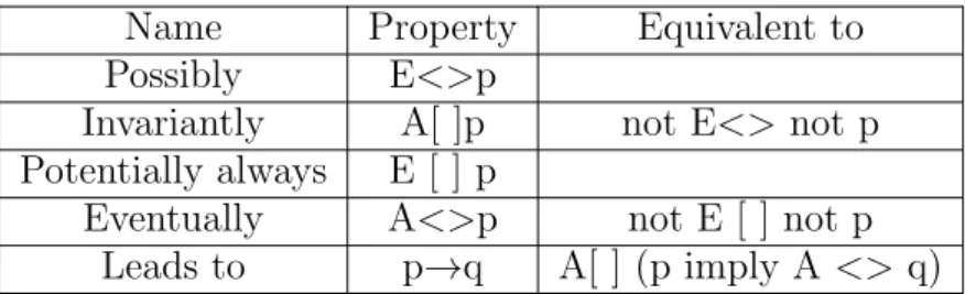
To test the reachability, safety and liveness properties, UPPAAL provides 5 verification languages, which can be summarised as follows Tab. 2.1:
• E <> p implies the possibility. E <> p is true if and only if there is a sequence s0 → s1 → ... → sn in the timed automata, where s0 is the starting state and sn is
p.
• A[]p is Invariantly, which is equal to E <> not p.
• E[]p means Potentially always. In the timed automata, when E[]p is true and if and
only if there is a sequence s0 → s1 → ... → si → ... where p is satisfied for all state
si, and this sequence is infinite or stopped at state (ln, vn).
• A <> p means Eventually, which is equal to not E[] not p.
• p → q denotes Leads to, which is identical to A[] (p implies A <> q).
2.5.3
A Simple Example
In this section, a simple example of model checking with UPPAAL is discussed. The train gate controls access to a bridge for several trains, as a railway control system. The bridge is a critical shared resource which can be accessed by only one train at one time. The system is defined as four trains and a controller. A train can not be stopped instantly and restarting also takes time. Therefore, there are timing constraints on the trains before
Safe Stop Cross x<=5 Appr x<=20 Start x<= 15 x>=10 x=0 x<=10 stop[id]? x>=3 leave[id]! appr[id]! x=0 x>=7 x=0 go[id]? x=0 (a) Occ Free e : id_t appr[e]? enqueue(e) e : id_t e == front() leave[e]? dequeue() stop[tail()]! len > 0 go[front()]! e : id_t len == 0 appr[e]? enqueue(e) (b)
Figure 2.3: (a) The train model and (b) the gate model in UPPAAL
entering the bridge. When a train approaches, it sends an appr! signal. Thereafter, it has 10 time units to receive a stop signal. This allows the train to stop safely before the getting to the bridge. After these 10 time units, it takes further 10 time units to reach the bridge if the train is not stopped. If a train is stopped, it resumes the course when the controller sends a go! signal to it after a previous train has left the bridge and sent a leave! signal. After 7 time units, this train passes through the bridge and send a leave! signal after 3 time units.
The model of the train gate has two templates. Train is the model of a train, and Gate is the model of the gate controller and the queue of the controller, shown in Fig. 2.3.
We check the simple properties and deadlock. The simple reachability properties are expressed as:
• E <> Gate.Occ : Gate can receive (and store in queue) msg’s from approaching
trains.
• E <> Train(0).Cross : Train 0 can reach crossing.
• E <> Train(0).Cross and (forall (i : id t) i != 0 imply Train(i).Stop) : Train 0 can
cross bridge while the other trains are waiting to cross. The following safety properties hold.
• A[] forall (i : id t) forall (j : id t) Train(i).Cross && Train(j).Cross imply i == j :
There is never more than one train crossing the bridge (at any time instance).
• A[] Gate.list[N] == 0 : There can never be N elements in the queue (thus the array
The form of the liveness properties is Train(0).Appr→Train(0).Cross. Whenever a train approaches the bridge, it will eventually cross. To ensure the system is deadlock-free, we verify the query A[] not deadlock.
Through model checking of the train gate system, we show what may happen. A train may cross the bridge but the following trains will have to stop.
Chapter 3
Construction of FlexRay Model
3.1
Overview of FlexRay Communication Protocol
Specification
This section gives explanations of the core of FlexRay communication protocol specifi-cation which are essential in building FlexRay model in UPPAAL. FlexRay protocols are first designed using specification and description language (SDL). For a automotive system based FlexRay, several nodes are connected by using star, bus and other topolo-gies, forming a functional system, which is called a cluster. Each node has bus driver to connect to bus. A node consists of an ECU, a controller host interface (CHI) and a communication controller (CC). Fig. 3.1 shows the structure of node in the FlexRay bus. Applications of communication system run on ECU of each node, which is a real time kernel that contains two schedulers for static cyclic scheduling (SCS) and fixed priority scheduling (FPS). ECU and CC share control and configuration information in CC, and also the processed data of ECU are stored in it. The CHI processes the data and controls the flow between the ECU and CC within each node. The CHI has two major interface blocks, the protocol data interface and the message data interface. The protocol data interface deals with all data exchange with regard to the protocol operation, while the message data interface manages all data exchange with regard to the exchange of messages as illustrated. The protocol data interface manages the protocol configuration data, the protocol data and the protocol status data. The message data interface handles the message buffers, the message buffer configuration and the message buffer status data.
The CC carries out the FlexRay protocol services. CC is the vital part in FlexRay com-munication model. The CC structure is defined in the protocol specification of FlexRay communication system, as shown in Fig. 3.2. It is divided to six parts as depicted as follows. Protocol Operation Control (POC) monitors overall status of CC and manages other parts. Media Access Control(MAC) is based on a recurring communication cy-cle. During one communication cycle, FlexRay provides the choice of two media access schemes, TDMA and flexible-TDMA. Frame and Symbol Processing (FSP) checks the correct timing of frames and symbols concerning the TDMA scheme, applies further syn-tactical tests to received frames, and checks the semantic correctness of received frames.
ECU: Electronic Control Unit CHI: Controller Host Interface CC: Communication Controller ECU CHI CC FlexRay Bus Node1 Node1 Node1 Node1 Node1 Node1 FlexRay Bus
Figure 3.1: The topology of FlexRay bus system
Bus driver deals with coding and decoding processes. Macrotick Generation (MTG) con-trols the cycle and macrotick counters and applies the rate and offset correction values. The clock synchronization processing (CSP) performs the initialization at cycle start, the measurement and storage of deviation values, and the calculation of the offset and the rate correction values. The clock synchronization startup processing executes the initializa-tion and commencement of the MTG process and the CSP process. This process has the repetitive tasks of measurement and storage of deviation values and the calculation of the offset and the rate correction values. Bus driver directs coding and decoding processes.
3.2
Abstracted FleRay Model
We abstract FlexRay communication protocol specification from the following three as-pects.
Firstly, we focus on the communication between nodes and assume that the commu-nication is in the case of clock synchronization and channel is no noise. The verification of design model of applications only needs functionalities of sending and receiving frames to be present in the FlexRay model. Therefore, only essential and necessary components for providing communication functionalities are selected. So the clock synchronization processing, the macrotick generation and the clock synchronization startup processing are out of our scope in CC. Instead, we use a simple mechanism for synchronization and startup between nodes. Moreover, the coding and decoding behaviors belong to the phys-ical layer channel. It has nothing to do with the communication clock. So the bus driver is removed.
Secondly, because the clock is synchronized and no interference in the normal commu-nication case, many function modules of CC become unnecessary. it is not necessary the FlexRay model to have the full behavior in sending and receiving frames. Behavior such as adjustments for error control, i.e. fault tolerance feature, can be skipped. So each module function has also been simplified on the basis of the communication function, and the details will be discussed in the next section.
frame and symbol processing media access control clock synchronization startup macrotick generation clock synchronization processing protocol operation control controller host interface coding / decoding processes channel A
frame and symbol processing channel A media access control channel A clock synchronization startup channel A
to channel interface from channel interface to / from host media access control channel B coding / decoding processes channel B frame and symbol processing channel B clock synchronization startup channel B ECU CHI CC Bus Driver
Figure 3.2: The structure of node
node. Due to the FlexRay system is very large and has a lot of states, out of memory happens when we check some properties in UPPAAL. Thus, we abstract FlexRay model again. A CC manages communication of all nodes. Due to FlexRay protocol is based on TDMA scheme, only one node can take channel In a moment. So we can through a CC to monitor all nodes, which send data in the specified time.
Fig. 3.3 is the simplified structure of nodes. In ECU, one or more tasks run on it. Different tasks can be designed according to the function of system in UPPAAL. In CHI, buffers are allocated for each ECU, where the generated data of the task is stored to
the corresponding buffer. For CC, this part realizes the time driven function of the
FlexRay protocol. For each part, we model their behaviors of sending and receiving messages, where these behaviors are related to time. POC monitors overall status of CC and manages other parts when system normally works. Timer controls the length of time slot. MAC is responsible for sending messages in special slots. FSP is responsible for receiving messages and transmiting data to tasks in ECU. By using the bus module as a buffer of storing frames, the transmission channel can be simulated.
POC
BUS
FSP MAC
Timer
ECU1 ECU2 ECU3 ………
………
data
signal CC
CHI
Figure 3.3: Simplified structure of node
macrotick arbitration grid level macrotick level microtick level communication cycle level
static segment dynamic segment
minislot
microtick
symbol window
t
action point
static slot static slot minislot
action point action point network idle time
Figure 3.4: Timing hierarchy within the communication cycle
3.3
FlexRay Model
3.3.1
Communication Cycle
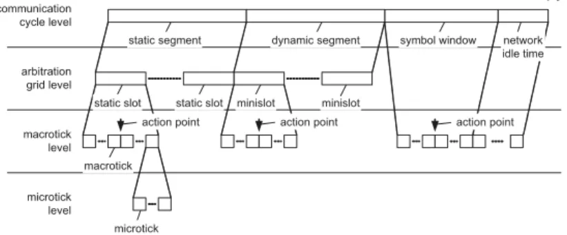
In FlexRay, communications take place in periodic cycles. In a cycle, FlexRay provides two kinds of communication schemes, the static TDMA and dynamic minislot-based FT-DMA with more flexibility. The time unit in the communication cycle can be divided into 4 parts: micritick level, macrotick level, arbitration grid level and communication level, as shown in Fig. 3.4. The length of microtick is determined by clocks of the FlexRay commination controller, where different nodes uses different clocks. The macrotick con-sists of several microticks, and the amount is determined by the clock synchronization mechanism. It should be noted that microtick is the minimum time unit for guaranteeing the overall clock synchronization. Multiple macroticks can compose one static slot in the arbitration grid level, or one minislot in the dynamic segment. There is an action
Tcycle Tcycle
1 2 3 4 5 6 7
1 2 3 4 5 6 7 8 9 10 11 12 13 Minislot counter Static segment Dynamic segment
Slot counter Static Slot tActionPoint Macrotick NIT tActionPoint
Figure 3.5: Communication cycle of FlexRay model
point in both the static slot and the minislot, as the offset from the its starting point. Arbitration grid level is the core part of FlexRay system, which determines the way of communications. In the highest layer a communication cycle contains the static segment, the dynamic segment, the symbol window and the network time (NIT). Both the static and dynamic segments are comprised of several corresponding slots, which are periodically repeated. The symbol window is a transmission period in which a symbol can be sent on the network. It is responsible for synchronizing the cycle between nodes. The symbol window contains a configurable number of maroticks. If no symbol window is required, it is possible to configure zero maroticks. The network idle time is a communication-free period, which contains all the macroticks which are not used in the previous three time units in one cycle. And it also reset the value of slot counter. The dynamic segment and the symbol window are not necessarily needed for every cycle, and the durations of them are adjustable as required. In our research, we ignore the symbol window, because in normal communications, it doesn’t need treatment the synchromism symbol between nodes and do not influence the time of sending message. And we only consider the time from the communication cycle to the macrotick level, as shown in Fig. 3.5.
The static segment uses TDMA to realize time-triggered bus access, with fixed time duration for each cycle. Static slots are numbered in ascending order from the very beginning. One or more static slots be allocated to the nodes. The allocation method is unchangeable during the operating, and the allocated static slots can only transmit message for specific nodes. Even when one static slot does not contain information data, the system will keep idle until the next static slot comes.
The dynamic segment is event-triggered, based on the mini-slot TDMA, and it is com-prised of a fixed amount of minislots. The time duration of the dynamic slot depends on the length of the message, which requires one or more minislots. The system will start the
next slot after other nodes finish receiving message.The dynamic slots also be allocated to different nodes which send the dynamic message only in specified dynamic slot. If there is no enough minislots for the message to transmit in one cycle, it will wait and check the next period. What if there is no information to send within a dynamic slot, all nodes will wait a minislot. Then dynamic slot counter will increase until the next minislot comes. The system will keep this procedure until the dynamic segment ends. If all the required transmissions finish before the dynamic segment ends, the system still has to wait for the rest of the segment duration.
According to the overall clock, different nodes determine the time for sending or receiv-ing a specific data frame with a particular ID, which is called the slot ID. To determine this specific time, every node uses a slot counter for both the static and dynamic segments, with the counter value being the current slot ID. During every static slot and dynamic slot, only one node is allowed to send message on the bus. Therefore, at the beginning of every slot, all the nodes have to check whether the message ID and the slot ID match with each other. If and only if they are matched, this message can be transmitted.
For static messages, ECU uses static cyclic scheduling(SCS), and during the period of the system design, the slot identifiers are allocated to nodes. The static messages are send according to the schedule table in ECU and the length of the transmitting data should abide by the specification defined in gPayloadLengthStatic. For dynamic messages, ECU uses fixed priority scheduling(FPS), and the message with smaller ID will be sent with higher priority. In one communication cycle, if there are a large number of nodes transmitting information, or the message length is too long, there is no enough minislots for the message with large ID to be transmitted in the period. In this case, it will wait for the next cycle. Obviously, it is quite uncertain that all messages are able to get the required bandwidth, which depends on how much messages has been transmitted previously. Hence, for the information data with strict delay requirement, it is essential to transmit it in the static segment, or allocate smaller ID (higher priority) in the dynamic segment.
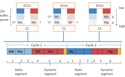
There is an example of FlexRay communication cycle, as shown in Fig. 3.6. This figure shows 3 nodes and how the messages are sent. At the beginning of the communications, CC configures the relevant parameters, with the slot counter and minislot counter return-ing to 0. There are the first two communication cycles, which are used to demonstrate the timing of message transmissions. Each node has two buffer queues to store static and dynamic messages in CHI. For the ST message, every ECU has a scheduling table of the transmission time. When it is the time of sending ST message, ECU will store the operation results into the buffer with relevant ID. Every static message is assigned with the cycle and slot numbers for transmitting in the specific time. For instance, if the message ‘Ma’ is assigned to the first cycle and the second slot by 2/1, it will be sent during the second slot of the first cycle. Similarly, ‘Mb’ will be transmitted in the first slot and of the first cycle and ‘Mc’ will be sent during the first slot of the second cycle .
For dynamic messages, every dynamic message is assigned with a slot ID. The dynamic messages are packed into frames by the bus driver with a frame ID being identical to the allocated slot ID. This ID also represents the priority in sending messages. For instance,
Ma Me Mc Mb Mf Mh Mg CC CC CC
ECU1 ECU2 ECU3
CHI buffer queue Mb Ma Mf Me Mc Mg 6 6 1/2 1/1 2/1 1 2 3 4 5 4 5 6 1 2 3 4 5 6 Cycle 1 Cycle 2 Static segment Static segment Dynamic segment Dynamic segment low high
Figure 3.6: FlexRay communication cycle example
the message ‘Mf’ has ID 4, so it is the forth slot to be sent in the first cycle. Then, the message ‘Me’ with ID 5 is sent in slot 5. Besides, if there are more than one messages shared the identical ID, like ‘Mg’ and ‘Mh’, to be transmitted within a same cycle, ECU will determine which one will be first transmitted according to the priority scheme. The messages with higher priorities will be sent in the current cycle. Clearly, ‘Mg’ has higher priority than ‘Mh’. But, the dynamic segment in first cycle does not has enough minislots for it. So ‘Mg’ is sent in slot 6 of the second cycle. If there is no message to send in the slot, like slot 6 in the first cycle, this slot still consumes a minislot.
As can be seen, the time of static messages transmission is predictable and its access to the bus is deterministic. However, by assigning time slots for nodes and messages to fix the bandwidth allocation, the bus bandwidth may not be fully used, and it is not flexible for the later nodes expanding. Due to these reasons, dynamic segment makes up for the weakness. It guarantees that messages with high priority still have the chance to be transmitted even when the bus is busy. The messages with low priorities will be sent when the bus is idle. In this case, nodes can share the bandwidth and the bandwidth can be dynamically allocated with more flexibility. The determinacy of the bus access can be guaranteed and the drawbacks of the static transmission are compensated.
3.3.2
Protocol Operation Control
In this sub-section, we discuss how CC is defined in different parts of the FlexRay commu-nication protocol specification, as well as the structure realization of the FlexRay model in UPPAAL. Every node of the FlexRay system has 6 basic Protocol Operation Control States and different functions are realized in different states, respectively. Hence, when the node ECU starts, the node states have to be transformed according to the relevant protocols for the normal communication. The stares transition diagram is shown as flows Fig. 3.7.
Default config wakeup halt Ready config
startup Normal active Normal passive
Figure 3.7: Overview of protocol operation control
• Config status (including Default Config and Config): for initializations, including
the communication period and data rate;
• Ready status: for the internal communication set;
• Wakeup status: to wake up the nodes which are not communicating. In this sate,
one node sends the wake-up signals other nodes, to awaken and activate the com-munication controller, the bus driver and the bus monitor;
• Startup status: to start the clock synchronization, as a preparation of the
commu-nication;
• Normal status (Normal Active and Normal Passive): normal active communication
status;
• Halt status: to indicate that the communication is in outage.
The FlexRay system has to be first initialized before getting to the ready status. Then, the node states and the relevant invariants are updated according to the CHI. During certain time duration, some nodes or the communication cluster do not work and are
in the power save mode. They should be awakened before being back to work, and
the awakened nodes can also wake up other nodes and the whole cluster. Next, the synchronous frames are sent during the same slot of every cycle. The slot counter and the cycle counter are initialized between nodes, and the clocks are synchronized by the clock synchronization startup module. At this moment, the POC starts MAC and PSF modules and then the system can achieve the normal communication status. In the communicating process, when POC receives the preempting deferred commands from other parts of the CC, and then it will jump to the halt state. Before the next communication cycle start,
vSS.vCycleCounter<gCycleCounterMax vSS.vCycleCounter==gCycleCounterMax vSS.vCycleCounter<=gCycleCounterMax x:=0 vSS.vCycleCounter=1 x<=startup_offset vSS.vCycleCounter++, x=0 start_up wait_for_cycle_end cycle_end? cycle_start! cycle_end?
Figure 3.8: Protocol operation control model in UPPAAL
if the error checking sends signals, POC will change the state according to the signals. For instance, if the node is configured not to allow the communication to be halted due to severe clock calculation errors, than POC will transfer to normal passive status.
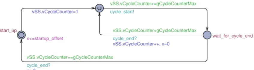
This research focuses on the properties of the communication time, which ignores the processes of the system launching and synchronizing. We only emphasize the data trans-mission and response in the normal communication status, and perform verifications to them. Therefore, only the model of POC in the normal active status is provided in this research. The diagram in UPPAAL is given by Fig. 3.8.
In the normal active status, the system has already finished initialization and synchro-nization procedures, and POC starts to execute a sequence of tasks at the end of each communication cycle. We use the start up as initial state. In this state, the time con-strained by the invariant x<=startup offset is smaller than that by startup offset, before the transmission. startup offset is a constant defined as 0, which indicates that the system starts timing when the normal communication begins. Before the first transmission, we set the Vss.vCycleCounter equal to 1, starting the first cycle. The POC model will check that if the current cycle number is less than or equal to the max cycle value
gCycleCoun-terMax, it will send a cycle start! signal to MAC, and MAC will start the first slot of
static segment. Then POC will go to the wait for cycle end state and wait until this cycle ends. At this moment, the first communication cycle begins, including static segment and dynamic segment. When the last minislot in the dynamic segment finishes, MAC will send a cycle end! signal to finish the first communication cycle. POC will again check which cycle it is at this moment. If Vss.vCycleCounter is less than gCycleCounterMax,
Vss.vCycleCounter will plus one and the next cycle starts. if Vss.vCycleCounter is equal
to gCycleCounterMax, POC will reset the system timing, re-configure the system and redo the previous processes.
3.3.3
Media Access Control
The media access control (MAC) deals with the usage of the public channel for the communication clusters when there is a competition. It is the most important part of the FlexRay model. In the FlexRay protocol, MAC is based on a recurring communication cycle, and it control the segments allocation during the communication cycle. Different media access schemes are employed in static segment and the dynamic segment. One cycle duration is divided into many slots with their labels in order, and the slots with
different ID are allocated to the relevant nodes. Therefore, frames sent from one node have the same ID at the head of them. The frame should only be sent during the time slots with the same ID, which efficiently avoids the nodes occupying the channel. The execution of MAC in detail is expressed by SDL in the FlexRay protocol specification, as shown in Fig. 3.9.
Figure 5-13: Media access process [MAC_A]. standby
MAC control on A (zMacMode)
zMacMode ? STANDBY
wait for CAS action point set (tCASActionPoint); transmit symbol on A (CAS_MTS) STARTUPFRAMECAS else tCASActionPoint STATIC_SEGMENT_A DYNAMIC_SEGMENT_A SYMBOL_WINDOW_A NIT_A dcl vSlotCounter T_SlotCounter; dcl vCycleCounter T_CycleCounter; dcl vTF T_TransmitFrame; dcl vTCHI T_CHITransmission; dcl zMacMode T_MacMode; dcl zMinislot Integer; dcl zEndMinislot Integer; dcl vLastDynTxSlot T_SlotCounter; dcl zTransmitStatFrame Boolean; dcl zChannelIdle Boolean := false; dcl vTransmitMTS_A Boolean; dcl vTransmitWUDOP_A Boolean; dcl zMinislotCE Integer; dcl zNoTxSlot Boolean; dcl zDTSReceived Boolean; dcl zFrameThreshold Boolean; dcl zActiveBits Integer; dcl zIncSlotCounter Boolean; dcl vDynResyncAttempt Boolean; dcl zFirstTTESlot Boolean := false; MT timer tCASActionPoint := cdCASActionPointOffset; MT timer tActionPoint := gdActionPointOffset; MT timer tSymbolActionPoint := MT timer tSlotBoundary := gdStaticSlot; MT timer tMinislo
MT timer tMinislotActionPoint := gdMinislotActionPointOffset; MT timer tSymbolWindow := gdSymbolWindow; MT timer tDynamicSegmentOffset := gdActionPointOffset - pExternalSync ?
zFirstTTESlot := true; true
false
TT-E time gateway sink beha-vior (optional)
Figure 3.9: Media access process
After the system starts, MAC will receive STANDBY command sent by POC, wait at the ready position and make decisions based on the received zMacMode. If it is STANDY, MAC will reset the internal communication and be back to the ready position; if it is
STARTUPFRAMECAS, it indicates that the collision avoidance action point need to be
reset, and CAS MTS testing symbol should be sent for CSMA/CD during this period. The MAC checks whether this node is synchronized with the other external nodes. If the value of zMacMode is none of the two mentioned above, the system will jump over the collision avoidance operation and directly check whether this node is synchronized. If the
pExternalSync value is true, zFirstTTESlot has to be set true, which belongs to the TT-E
time gateway sink behavior; if the pExternalSync value is false, the system will jump over this step and repeatedly start the communication cycle from static segment.
Figure 5-16: Media access in the static segment [MAC_A].
cycle start (vCycleCounter)
static segment start on A (vCycleCounter, vSlotCounter) transmit frame on A (STATFRAME, vTF) tActionPoint tSlotBoundary vSlotCounter ? else > gNumberOfStaticSlots slot boundary on A (vSlotCounter) STATIC_SEGMENT_A ASSEMBLE_ STATIC_FRAME_A action point on A frame vTF to transmit nothing totransmit zTransmitStatFrame := true; zTransmitStatFrame ? true set (tActionPoint); set (tSlotBoundary); zTransmitStatFrame := false; vSlotCounter := 1;
’update vSlotCounter on A in CHI’;
wait for the action point
vSlotCounter := vSlotCounter + 1; ’update vSlotCounter on A in CHI’; wait for the cycle start
false
wait for the static slot boundary
Figure 3.10: Media access in static segment
The MAC for static segment is shown in Fig. 3.10, and the main functions are slot number counting, action point setting, frame assembling, frame transmitting and process
cycling\starting dynamic segment. First of all, the system wait for the cycle start until
the cycle counter start counting. The initial value of the slot counter is set at 1 by MAC when starting the first static slot, and the vSlotCounter value in CHI has to be updated. Then, the channel is informed that the static segment can start and the values of current cycle and slot can be assigned. The action point and slot boundary time of the static slot should be set and let zTransmitStatFrame be false. If there is no information data to be sent, MAC jump back to wait for the action point state. When the action point time is out, the channel is informed, and MAC will check zTransmitStatFrame and see whether there are information data to be sent. Specifically, if it is true, frame transmission takes place. Otherwise, MAC will go to wait for the static slot boundary state until this static slot ends. At the time edge of this slot, the slot counter will plus 1, and the slot counter value in CHI will be updated. Finally, the slot counter value is checked. If it is no larger than the maximum value of the static slot number, the next static slot will start and the parameters such as the action point will be reset; otherwise, it indicates that the static


![Figure 5-13: Media access process [MAC_A].](https://thumb-ap.123doks.com/thumbv2/123deta/6098255.1076085/35.892.347.547.303.787/figure-media-access-process-mac-a.webp)
