Japan Advanced Institute of Science and Technology
JAIST Repository
https://dspace.jaist.ac.jp/Title
Method of Object Extraction for Architecture : Object Approach towards a Logical Design Focusing on User Knowledge
Author(s) Mitsui, Yasuhiro; Nagai, Yukari; Taura, Toshiharu Citation
Issue Date 2007-11
Type Conference Paper
Text version publisher
URL http://hdl.handle.net/10119/4088
Rights
Description
The original publication is available at JAIST Press http://www.jaist.ac.jp/library/jaist-press/index.html, KICSS 2007 : The Second International Conference on Knowledge, Information and Creativity Support Systems : PROCEEDINGS OF THE CONFERENCE, November 5-7, 2007, [Ishikawa High-Tech Conference Center, Nomi, Ishikawa, JAPAN]
Method of Object Extraction for Architecture:
Object Approach towards a Logical Design Focusing on User Knowledge
Yasuhiro Mitsui† Yukari Nagai† Toshiharu Taura‡
†Department of Knowledge Science Studies,
Japan Advanced Institute of Science and Technology
‡Graduate School of Science and Technology, Kobe University
{YasuhiroMitsui, ynagai}@jaist.ac.jp, [email protected]
Abstract
In the conventional method of architecture, plan-ning is done according to the building type, the framework of the past or existing buildings, by referring to the user requirements provided by the user ([6], [4]). This process does not depend much on the user requirements, but on the build-ing types. However, architectures built accord-ing to the buildaccord-ing types cannot meet contempo-rary user’s requirements, which are specialized and diversified. A revolution in the building types, therefore, is an ambitious architectural goal to achieve [3].
To implement an architecture independently of the building types, it is crucial to obtain suffi-cient user requirements in order to be able to use them in the design process. But there is no method to bring the viewpoint of the user into the process of architectural planning [1]. The Method of Object Extraction for Architecture (OEA method) is a new method to realize it us-ing object technology. Its recursive process and visual diagrams help the user to remind uncon-scious knowledge and to generate new knowl-edge of the requirements for the building. As a result, the OEA method extracts the user’s knowledge thoroughly and translates it into documents effectively.
This article is an introduction to the OEA method. We apply the method to a real house building project to analyse its results and design process. We also contrast the features of the OEA method with two other methods of archi-tectural analysis and logical design, to illustrate how the method realizes comprehensibly a logi-cal view of the building.
Keywords: Architectural Planning, House
Design, User Requirements, Knowledge Science, UML
1 Introduction
1.1 Background
Analysis and logical design are often treated comparatively lightly in architectural design. Architectural design work can be divided into two big phases: design planning, which includes analytical work and logical design, and design-ing, which includes physical design [4]. Al-though requirement definitions for architecture are the first stage of logical design and the source for all planning, they take a small part of the design planning phase, which also contains physical design such as scale planning, situation planning, ground planning, structure planning, etc. The requirement definitions are usually treated simply as given by the user. Even in the Programming of W. Peña [6], which is a method of architectural analysis widely used around the world and a part of the American Architect Reg-istration Examination, user requirements can be obtained through a questionnaire and by stimu-lating the user to decide. All of this results in an informal collection of requirements depending on the talent and the experience of each architect. Consequently, the quality of the requirement definitions tends to be unavoidably inconsistent.
After collecting imperfect requirements, an architect designs a building based upon corre-sponding building types which were typical ar-chitectural frameworks prepared through the study of currently existing and past buildings (e.g. hospital, school, house, etc.). The innova-tion in the building types has been said to be crucial, since the current types are based upon past usage of the buildings, and then they cannot always satisfy the individuals’ varied and spe-cialized modern lifestyle any more [3].
The Architecture Planning Committee of the Japan Architecture Society discussed in a
sym-posium about the fact that there are regrets that few attempts to include the viewpoint of the user in the process of architectural planning had been done, and that the method for doing it was still hesitant [1]. A typical case could be seen in the public building competition held by Akita City in 1998 [8]. The user requirements that were part of the competition specifications were far from comprehensive, and neither concrete nor spe-cialized. The applicants must provide the plan-ning documents for at least three floors given insufficient user requirements, though there were many conditions in terms of laws, physical restrictions, administrations and contracts.
These problems cause a lack of formal method to extract user requirements sufficiently.
1.2 Purpose
To achieve a unique physical design independ-ent of building types, it is necessary to obtain explicit and comprehensive documents describ-ing user requirements which are a thorough ex-traction of user knowledge for the building. By obtaining such documents, the architect can guarantee the user that the building satisfies the requirements even if it is designed as the most unique building that has ever existed. The pur-pose of this paper is to introduce a new method which extracts such documents from the users.
1.3 Method of Object Extraction for Archi-tecture
How can we achieve this aim? We cannot just ask the user to provide the requirements from his own knowledge, since the user is not conscious of the entire requirements at the beginning. Even the user is not usually conscious of who actually uses the building. Often the user who joins the design work is the owner of the building, but real users of the building include many more actors [5] as well as the owner. For example, the owner of a house is a family, and the real users of the house include not only family members who live in the house, but also customers, guests who stay overnight, a gardener who cares for the trees and plants regularly, and a potter who is the father, whose hobby is pottery.
The user, of course, has plenty of knowledge about his own building, but some of his own knowledge for the requirements is unconscious, and some has not been found yet. The user has to think about them and create them, since they are potential. The purpose of the OEA method is
to extract the entire user knowledge for the re-quirements using the features of object technol-ogy [2]: principle or nature, object model, ob-ject-oriented analysis and design, etc. Employ-ing the OEA method in a public buildEmploy-ing com-petition will allow to add comprehensive, more concrete and specialized user requirements to rather equivocal specification documents.
2 Methods
2. 1 Application Project of the OEA Method
In order to analyse the process and obtain the results of creative design, we applied the OEA method to the real house building project of family F. carried out in Fukuoka Prefecture, in Japan. Mr and Mrs F. joined the project as users of the house and the primary author of this paper conducted the process. The method was applied by holding four interviews of about three hours each, from September to December 2006. Also, some homework was done by the users between the interview sessions. All of the resulting docu-ments are sorted and written out fairly by the conductor of the process.
After the completion of the resulting docu-ments, the F. family’s house design competition was held in June 2007. Four architects partici-pated in the competition. We analysed two con-trasting resulting plans.
2. 2 Process of the OEA Method
The OEA method has three phases of analysis: the Use Case Analysis, the Scenario Analysis, and the Architectural Object Analysis.
The Use Case Analysis is the phase in which the user of the building thinks about and finds out who the real users (called actors) of the building are and how the actors use the building (called use cases). The purpose of this phase is to draw use case diagrams for the building using the use case specification defined by the Object Management Group (OMG) as a part of a UML (the standard object-oriented analysis and design language) specification [5]. A use case diagram is visual and easy to understand for both the user and architect. The resulting documents of the phase are Use Case Diagrams.
The Scenario Analysis is for the user to think about concrete procedures for each use case. Here, step-by-step scenarios for regular cases and special cases are written by the users. The resulting documents of the phase are Scenarios.
Architectural Object Analysis uses a descrip-tion of all scenarios to extract all objects which are used for or related to the building. We call them architectural objects. The nouns are picked up from the scenarios and merged into architec-tural objects, their attributes or parts. After that, the verbs related to the architectural objects are picked up to be their functions. All architectural objects are sorted into lists with a view of object relationships. The lists are categorized according to the purpose. All objects can be assembled into Object Diagrams which represent logical views of the building with a whole-part relationship. The resulting documents of the phase are Lists of Architectural Objects and Object Diagrams.
It is expected that the architect will be able to use the results as logical design documents: Ob-ject Diagrams for the logical structure of the building, a List of Architectural Objects for the details of building objects, Use Case Diagrams for an overview of the building usage, and Sce-narios for the details of the usage.
For the user, it is important for the process of the OEA method to be recursive, that is one of the natures of object technology. The user, therefore, can draw upon his own knowledge, which includes unconscious knowledge and not-yet-found knowledge, by interacting with the resulting documents.
3 Results
In this section, we will present some examples
of resulting documents of the OEA method and resulting plans with and without using the OEA documents from the design competition.
3.1 Resulting Documents of the OEA Method
We found that the process of the OEA method for the F. family’s house project took time, but it was not wasteful to go back. The resulting documents were built cumulatively in the recur-sive process with an interaction between the user and the documents. This design process is dif-ferent from the informal or architect-dependent process which consists in repeating interviews to obtain the requirements.
The resulting documents of the application project of the OEA method were Use Case Dia-grams, Scenarios, a List of Architectural Objects and Object Diagrams, which would be a logical design for the house.
Use Case Diagrams
Fig. 3.1 is the main use case diagram of the F family’s house. The biggest rectangle with a bold line represents the house. The line drawing figures around it are actors. Ellipses on the dia-gram are use cases which represent how the ac-tors use the house. The symbol with big and small combined rectangles is called a package, which indicates that there is a collection of use cases. These descriptions follow the UML speci-fication of the OMG [5].
All actors and use cases were found by the F. family. Interestingly, they found a thief as a negative actor who tries to get into the house (bottom left in Fig. 3.1.). They wrote a scenario for the use case of the thief (see Fig. 3.3., later in the Scenarios paragraph), and it resulted in an outside object, the Dark ground of the house (seen in Fig. 3.5., later in the List of
Architec-tural Objects and Object Diagrams paragraph).
We regarded this as a sample of not-yet-found knowledge of the users.
Visit, Stay and Live packages have a rela-tionship of inheritance (see Fig. 3.1.). The Live package is extended from the Stay package,
which is itself extended from the Visit package. This means that, if an actor is connected to the Live package, the actor has use cases of all three packages (for further technical details on inheri-tance, see [2], [5]). We have found a total of eighty-two use cases for the house.
Scenarios
One or more typical step-by-step procedures were written for the use case. Three scenarios related to the small kitchen object are shown in Fig. 3.2 below.
MAKE PICKLED UME, UME LIQUOR AND RAW CITRON PEPPER (from Live Package)
1. Gather materials from the parents’ home or from the vegetable garden. 2. Do preparation in the small kitchen at the back door under the eaves.
3-a. Put umes in bamboo sieves and dry them in the foods-drying place which is exposed to a lot of sunshine and hide from view from the entrance and living & dining room.
3-b. Open the door and go into the food storage area, which has a 4.5 tatami size floor, to make pickled ume, ume liquor and raw citron pepper.
GATHER VEGETABLES (from Live Package)
1. Gather vegetables from the vegetable garden.
2. Wash muddy vegetables and put unnecessary leaves into the compost bin in the small kitchen. 3-a-1. Take off shoes at the ‘taking-off-shoes’ place when you enter the food storage area. 3-a-2. Put the vegetables in the food refrigerator in the food storage area.
3-b. Dry onions and persimmons in the food-drying place which is exposed to a lot of sunshine.
BARBECUE (from Visit Package)
1. Get materials from the kitchen to the barbecue table in the garden. 2. Get charcoal, a folding table and chairs, a gridiron, etc. from the garage. 3. Barbecue.
4. After the barbecue, wash the gridiron, etc. in the small kitchen.
5. Put burning charcoal into the charcoal pot. Dig in the garden and bury the ashes. Figure 3.2. Scenarios of Use Cases related to the Small kitchen object The example below is the use case of the thief,
‘try to get into the house’. The scenario shows
that the house has a function such that the thief failed to get into the house.
TRY TO GET INTO THE HOUSE
a-1. Try to get into the house through the dark ground of the house.
a-2. The dark ground of the house is covered with security gravel, which makes sounds, which scare the thief and make him run away.
b-1. Try to get into the house, but the slide shutters are closed and locked; consequently, the thief failed.
Figure 3.3. Scenario of the Use Case ‘try to get into the house’ of the ‘Thief’ actor
List of Architectural Objects and Object Diagrams
Architectural objects picked up and sorted from
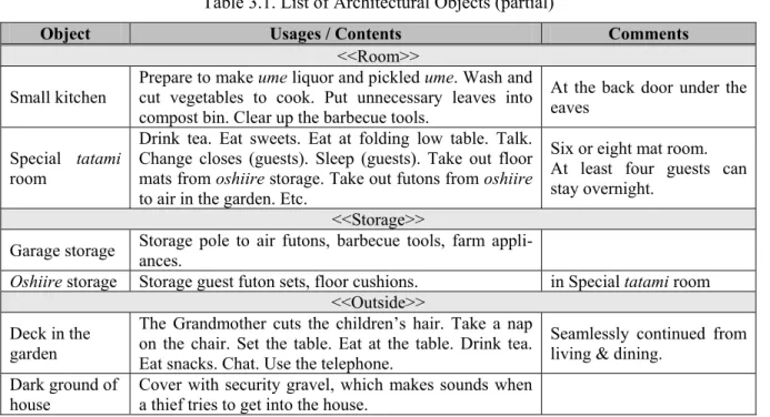
the scenarios are categorized and assembled into the List of Architectural Objects. Here are some examples for three categories Room, Storage and Outside (Table 3.1).
Table 3.1. List of Architectural Objects (partial)
Object Usages / Contents Comments
<<Room>> Small kitchen
Prepare to make ume liquor and pickled ume. Wash and cut vegetables to cook. Put unnecessary leaves into compost bin. Clear up the barbecue tools.
At the back door under the eaves
Special tatami room
Drink tea. Eat sweets. Eat at folding low table. Talk. Change closes (guests). Sleep (guests). Take out floor mats from oshiire storage. Take out futons from oshiire to air in the garden. Etc.
Six or eight mat room. At least four guests can stay overnight.
<<Storage>>
Garage storage Storage pole to air futons, barbecue tools, farm appli-ances.
Oshiire storage Storage guest futon sets, floor cushions. in Special tatami room <<Outside>>
Deck in the garden
The Grandmother cuts the children’s hair. Take a nap on the chair. Set the table. Eat at the table. Drink tea. Eat snacks. Chat. Use the telephone.
Seamlessly continued from living & dining.
Dark ground of house
Cover with security gravel, which makes sounds when a thief tries to get into the house.
All Usages/Contents and Comments are also picked up from the scenarios. This list is a kind of cross-reference between objects and functions, i.e. nouns and verbs from the scenarios.
Let us examine, as a typical example, ‘small kitchen’: first, we selected the noun ‘small kitchen’ found in the description of the Scenar-ios to be an architectural object; second, we picked up the nouns and verbs related to ‘small kitchen’ from the Scenarios. The related nouns and verbs became attributes, functions or related parts (child objects) of the ‘small kitchen’ object. The usages of ‘small kitchen’, which became functions of the ‘small kitchen’ object, were seen in Table 3.1. The four functions were sought and picked up from the scenarios of three use cases which had the noun ‘small kitchen’, as seen underlined in Fig. 3.2, and so was the com-ment ‘At the back door under the eaves,’ which
is an attribute of the ‘small kitchen’ object, from the second item of the first scenario.
All architectural objects were extracted from the Scenarios in the analytical process of this kind. Once the Scenarios are fixed, the logical design of the building will, therefore, be deter-mined accordingly. We have found eighteen ob-jects for the room category, eleven obob-jects for the storage category, fourteen objects for the outside category, and 103 objects to put in rooms and outside. The total number of objects was 146, which were all nouns extracted from the scenarios.
Fig. 3.4 is an Object Diagram which repre-sents the logical design of the house. This dia-gram is composed of the eighteen room category objects. The diamond symbols represent whole-part relationships.
Figure 3.4. Object Diagram of the F. family’s House.
Study room Passage Small kitchen Kitchen Dressing room Washroom
F family House <<Room>>
Food storeroom Entrance Toilet Bathroom
Family entrance Guest entrance
Parents’ bedroom Children’s bedroom Tatami room
3.2 Plans Resulting from the Competition
with and without the OEA documents
Two architects’ plans of the F. family’s house by four participants of the design competition are shown in this section. One architect named Y.S. read the OEA documents very carefully and de-signed the house according to them, the other, named A.W., did not refer much to the OEA
documents and designed the house with his usual method. Both architects had seen the land where the house would be built, and had met and talked with Mr and Mrs F. for a few hours at that time.
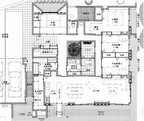
Fig. 3.5 shows a plan by Y.S., who followed the OEA documents, while Fig. 3.6 shows a two-storied house plan by A.W., who did not.
Figure 3.5. Plan by Architect Y.S., with the OEA documents
First floor
Figure 3.6. Plan by Architect A.W., without the OEA documents We have compared the floor plans of both
ar-chitects to the List of Architectural Objects
which represents user requirements. Tables 3.2 and 3.3 below show if the plan met the architec-Ground floor
tural object requirement. Here, ‘yes’ means that the plan satisfied the object requirement explic-itly, ‘possible’ means that the plan possibly sat-isfied it, and ‘no’ means that it did not satisfy it
for some reason. Only ‘no’ was counted as not meeting the requirements, and the object re-quirement satisfaction rate was calculated.
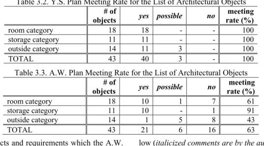
Table 3.2. Y.S. Plan Meeting Rate for the List of Architectural Objects
# of
objects yes possible no
meeting rate (%) room category 18 18 - - 100 storage category 11 11 - - 100 outside category 14 11 3 - 100 TOTAL 43 40 3 - 100
Table 3.3. A.W. Plan Meeting Rate for the List of Architectural Objects
Room objects and requirements which the A.W. Plan did not satisfy are shown in Table 3.4
be-low (italicized comments are by the authors).
Table 3.4. Room Objects and Requirements which the A.W. Plan did not meet
Object Requirements not met by the A.W. Plan
Parents’ Bedroom The room should not be exposed to the afternoon sun. Sounds from the toilet never reach the room. (The room is located on the first floor with 10.0 tatami) Children’s Bedrooms The rooms should be located where the parents can take every possible care of
the children, such as next to the living room. The rooms should be made good use of after the children leave the house (The rooms are separated on the first floor).
Study Room Use a PC. Take a book from a bookshelf. Read a book. Drink tea. Use the tele-phone. Listen to the music. (The room is omitted)
Kitchen A Kitchen Working Table is necessary to cook, dish up a meal and to bring dishes to the dining table. Four to five persons cook together in the kitchen (not enough space).
Entrance or Garage The Coop. delivery person puts an armful nest of boxes of food materials under the eaves where guests cannot see.
Bathroom When it snows, go out from the door (directly from the bathroom, naked). Food Storeroom Make pickled ume, ume liquor, raw citron pepper and so on. Drink at the
fold-ing table. Use the telephone. (The room is omitted)
4 Discussion
4.1 Comparison with Other methods
We contrast the features of architectural analysis and logical design of the OEA method with two other methods: Architectural Programming and the Evaluate Grid Method.
Architectural Programming by W. Peña
The Programming is an analysis directed by a Programmer. It is prior to Designing, which starts with a master planning or conceptual de-sign directed by a Dede-signer [6].
In the Programming, the user requirements are obtained by questionnaires at the beginning and by stimulating users to decide in the following work sessions. There is no concrete method pro-vided. Consequently, the quality depends on the ability and experience of the Programmer. We believe that it is useful to integrate the OEA method into the process of Programming.
Evaluate Grid Method
This is an interview method for user requirement analysis. The method was developed by means of improving the interview method used in
# of
objects yes possible no
meeting rate (%) room category 18 10 1 7 61 storage category 11 10 - 1 91 outside category 14 1 5 8 43 TOTAL 43 21 6 16 63
clinical psychology. The resulting document, Evaluation Structure Diagram, is composed of the user requirements and the ideas to implement them. The procedure to extract the user require-ments consists in, first, providing the user with various photos of buildings and asking to group them according to one’s degree of satisfaction, and then by asking the reason why. The method argues that this process illustrates the user re-quirements [7].
The Evaluate Grid Method is a kind of inter-view method to conduce the user to talk about his tastes and evaluation of the buildings. Struc-turally, it lacks the comprehensiveness aiming to reach a complete model of the building. We therefore cannot use the resulting document Evaluation Structure Diagram as a logical design of the building.
4.2 Effectiveness of OEA method
The process of the OEA method made the users remind and find their knowledge about the building. We mentioned the example that the F. family found: the Actor ‘thief’ who ‘tries to get into the house’ (Fig 3.5). That finding or dug-up knowledge resulted in a design considering ‘se-curity gravel’ (bottom of Table 3.1) which is implemented in the architect Y.S.’s plan as a shaded square visible at the top-middle and at the right side of the garage in Fig. 3.5.
Without the OEA documents, architect A.W.‘s plan meets only 63 % of user require-ments, while Y.S.’s plan meets 100 % with the OEA documents. There are some serious defects in the plan of A.W. regarding room objects, as seen in Table 3.4: the Parents’ Bedroom may have to be moved from the northwest corner to somewhere else, the Kitchen space must be ex-panded, and two important rooms should not be omitted, unless the users abandon or change their requirements.
4.3 Conclusion
The aim of the OEA method is to not neglect the current architectural design process. The method makes the logical design of architecture richer than ever by introducing a systematic or formal analytical method focusing on user knowledge.
Through the application of the OEA method
to a house building project, we could confirm that the three recursive analyses extracted user requirements which can be a rich base for the physical design of the house.
The user could just concentrate to think about real users of the house (actors), their usages of the house (use cases) and their step-by-step pro-cedures (scenarios). As a consequence, this brought forth all the architectural objects, and the logical design of the house.
Acknowledgment
We wish to thank the F. family and Forza, the architectural produce company, for their perse-vering cooperation, which lasted for months. We are also grateful to the two architects A.W. and Y.S. for gracefully allowing us to use their de-sign documents.
References
[1] The Architecture Planning Committee, Japan Architecture Society (1989). Design Methods and Design Subjects, Shokokusha.
[2] Graham, Iam (1994). Object-oriented Meth-ods, second edition, Addison-Wesley Publishers Ltd.
[3] Hattori, Mineo, Sato, Hitoshi et al. (2002) Architectural Design Planning: for new archi-tectural planning, Asakura Shoten.
[4] Nagamori, Kazuo (2004). Planning for Ar-chitecture Textbook, Inoue Press.
[5] Object Management Group (2005). Introduc-tion to OMG's Unified Modeling Language (UML),
http://www.omg.org/gettingstarted/what_is_uml. htm, Object Management Group.
[6] Peña, William, Parshall, Steven et al. (1987). Problem Seeking: An Architectural Program-ming Primer, John Wiley & Sons Inc.
[7] Ujikawa, Masato (2001). Humanizing of Architectural Space: Human space creation us-ing environmental psychology, Japan Architec-ture Society (Ed.) Shokokusha.
[8] Akita City, Akita, Japan Public competition specification for the multi-function complex core buildings planning (1998). “Akita port
renaissance 21 project” http://www.city.akita.akita.jp/city/in/hb/port/co