Volume 11, Number 1, August 2015, pp.13-16
[Summary]
The evaluation methodology of ground conditions ahead of a tunnel face by
means of inclination monitoring during the excavation
Takuya TANI*, Tomoyuki Aoki*, Kazuo SAKAI* & Naoya KUDOH**
* Taisei Corporation Technology Center, Yokohama, Japan ** Taisei Corporation, Kansai Branch, Osaka, Japan
Received 25 08 2015; accepted 27 08 2015
ABSTRACT
In a mountain tunnel construction project, the precise evaluation and prediction of ground conditions ahead of the tunnel face are necessary for the installation of proper auxiliary methods and the validation of designed support patterns. This could lead to a cost optimization and safety construction. In order to predict the ground condition, the authors have developed an inclination monitoring system, comprising a small-diameter tilt sensor named TT-Monitor (Tunnel Tilt Monitor), the evaluation methodology of measurement data, and the visualization of prediction results. This paper describes an overview of the forward prediction mechanism by means of three-dimensional numerical analysis. It then illustrates the way to measure and evaluate the inclination angle by the TT-Monitor with the tunnel advance. Lastly some typical results of a field demonstration test are presented. The results clearly show the validation and applicability of our proposed methodology
Keywords: Mountain tunnel, Inclination monitoring, MEMS, Forward prediction, Three-dimensional analysis
1. INTRODUCTION
In a conventional planning of a mountain tunnel, seismic refraction surveys from the ground surface are performed and tunnel support patterns are then designed based on the seismic wave velocity. The resolution of the velocity profile estimated by this technique, however, is poor as the tunnel overburden becomes large. The tunnel face is therefore often encountered by unforeseeable fault zones or weak rocks. Such an unpredictable weak zone occasionally causes the collapse of the tunnel face. Clarifying the forward geological information during excavation is hence significant for safe construction. According to the geological conditions ahead of a face, auxiliary methods typified by forepiling and face bolting could be preliminary taken into consideration.
For the purpose of acquiring forward geological information, pilot borehole drilling and seismic reflection methods represented by the TSP (Tunnel Seismic Prediction) or HSP (Horizontal Seismic Profiling) are often applied. Those borehole exploration methods are carried out near the tunnel face for a couple of days. This often leads to the interruption of excavation procedure and has no small effect on the construction schedule. We therefore have developed a novel methodology of monitoring slight inclination at the tunnel crown near the face, so that the forward ground conditions can be predicted and evaluated as part of a routine measurement procedure. The principle of the methodology will be described in the following section.
2. EVALUATION METHODOLOGY
2.1 The variation of tunnel crown’s inclination according to face advances (Tani et al., 2015)
Figure 1 shows an exaggeratedly schematic diagram of the displacement distribution in a longitudinal section of a tunnel. With the tunnel face advance, the ground deforms as shown by the arrows in Figure 1. If we focus on the cross section A, the current face position, the vertical displacement is theoretically about 30% of the total amount due to the tunnel excavation. The tunnel deformation rapidly progresses with the advances of the tunnel face through the point of interest. Finally the displacement converges to the position indicated by the red lines in the figure. In the situation mentioned above, the amount of displacement before convergent state varies in accordance with distance from the face, particularly near the face. The closer the measurement locates to the face, the smaller the crown settlement occurs as shown in the left diagram in Figure 2. In view of the vertical direction, the settlement near the face is clearly less than that far from the face. After the tunnel face is advanced substantially, the sensor installed vertically at the crown in Section B will incline toward the direction of tunnel face as shown in the right diagram in Figure 2. In this way, the tilt sensor tips forward and registers small inclination angles.
14 T. TANI et al. / International Journal of the JCRM vol.11 (2015) pp.13-16
2.2 Overview of the prediction methodology through a numerical analysis (Kudoh et al, 2012)
Figure 3 shows the three-dimensional analysis model used to analyze the surrounding rock of a tunnel and crown inclination angle. It is assumed the tunnel is advanced from right to left. The numerical model simulates the tunnel excavation when a weak rock is located anteriorly in the direction of excavation. In the figure, the ground on the right has a higher elastic modulus of 1,000MPa while soft rock on the left has smaller elastic modulus of 100MPa.
Figure 4 shows the calculated increment of inclination angles at the tunnel crown. The initial angle (inclination angle = 0 degrees) is set at the cross section 1m behind the face, considering the actual installing procedure of the sensor. The plot showed in the figure is calculated at the face 3m away from the measurement section; just after 2m excavation. The absolute values of angles are practically constant when the tunnel face is far away from the hard/soft rock boundary. However it drastically increases when the tunnel face goes into the weak rock. Focusing on the part just before the hard/soft rock boundary, slight accelerating tendency in the inclination angles is observed, as shown in Figure 5. The forward ground condition can be predicted by evaluating such
changes from steady value of inclination angles. The realization of this methodology requires the development of high-resolution tilt sensor with a small diameter, considering the sensor installation in the borehole drilled close to the crown. Next chapter describes the development of tilt sensor and the measurement layout at an actual tunnel construction site. Section A : Tunnel face Line of tunnel floor before excavation Line of tunnel crown before excavation Direction of excavation Converged lines of tunnel wall
Figure 1 Schematic figure of a tunnel deformation near the face (Tani et al., 2015)
Figure 2 Left: Tilt sensor’s state just after the installation Right: Tilt sensor’s state when the face is far from
the measurement section (Tani et al., 2015)
Figure 3 Three-dimensional analysis model
-4.0 -3.5 -3.0 -2.5 -2.0 -1.5 -1.0 -0.5 0.0 -20.0 -15.0 -10.0 -5.0 0.0 5.0 10.0 15.0 20.0 Inc lina tio n an g le ( d eg re es )
Distance from stratum boundary (m)
Inclination angle at 3m away from the face
E=100MPa E=1,000MPa
Direction of Exacavation
hard/soft rock boundary Refer to Figure 5 about
detailed variation of data
Figure 4 The increment of inclination angles at the tunnel crown (Three-dimensional analysis results)
‐0.376 ‐0.375 ‐0.377 ‐0.376 ‐0.379 ‐0.379 ‐0.382 ‐0.383 ‐0.390 ‐0.395 ‐0.413 ‐0.446 ‐0.603 -0.70 -0.65 -0.60 -0.55 -0.50 -0.45 -0.40 -0.35 -0.30 -15.0 -12.0 -9.0 -6.0 -3.0 0.0 3.0 Inc lin at io n an g le( d eg rees )
Distance from stratum boundary (m)
Inclination angle at 3m away from the face
E=100MPa E=1,000MPa
Direction of Excavation
hard/soft rock boundary
Figure 5 The detailed variation of angles focused on the part just before hard/soft rock boudary
Figure 6 TT-Monitor
Table 1 Specifications of TT-Monitor
Diameter (mm) 42 (Outer), 34 (Inner) Length (mm) 600 (Outer), 370 (Inner)
Weight (kg) 0.8
Operation range (degrees) ±15 Resolution (degrees) 0.001 Operation temperature (℃) -10~80
Power source Li-ion battery Operating voltage (V) 3.1~4.4
Memory EEPROM
Memory capacity 2,000 words, FIFO Mesurement interval 1,2,3,5,10,20,30 min
T. TANI et al. / International Journal of the JCRM vol.11 (2015) pp.13-16 15
3. SMALL-DIAMETER TILT SENSOR, TT-MONITOR Small-diameter tilt sensor named TT-Monitor was developed for the purpose of monitoring the slight tilting information, optimizing tunnel operation (Tani et al., 2014). The TT-Monitor consists mainly of a tilt angle measuring unit containing a MEMS accelerometer and the outer tube (see Figure 6). Table 1 gives the specifications of the TT-Monitor. To install the TT-Monitor the tilt angle measuring unit is set inside the outer tube, and only the inner unit is recovered after the measurement.
Figure 7 shows a conceptual longitudinal section of a tunnel with the typical measurement layout by the TT-Monitor. Similar to the convergence and settlement measurements performed in the observational construction in mountain tunnels, this method may be implemented as one of the routine management measurements. Since the sensors for monitoring the tilt angle are easy to handle, small and light, a worker readily can install them within a few minutes. They are fixed to the natural ground by means of mortar as used for rockbolt fixing. In addition, since the data is automatically logged to an internal memory and can transfer them via Bluetooth wireless system at any time, there is no need for wiring and the wire protection.
Theoretically, the TT-monitor indicates a constant value in the homogeneous ground condition, however a significant change from a steady value occurs, where a weak rock as represented by a fault zone exists ahead of the face.
In order to help the site engineers to judge a forthcoming
geological change, as illustrated above, the visualization system of evaluation results has been developed (see Figure 8). This system provides visually the existence of a weakened zone and its degree of weakness compared to the current rock conditions.
4. FIELD DEMONSTRATION TEST
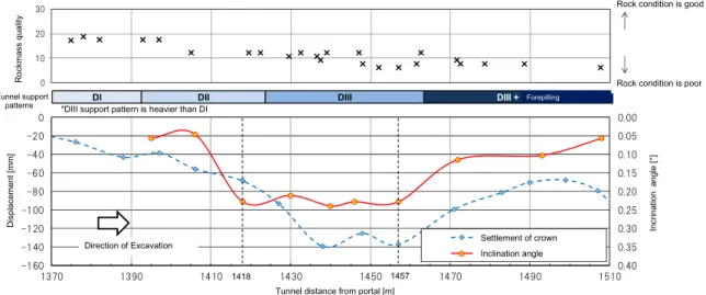
A field test was executed at a zone of very weak Mesozoic rocks with the overburden less than 80 m (Tani et al., 2015). Figure 9 shows the measurement data with the tunnel advance. The red circles connected with a red solid line indicate inclination angles, whereas the blue diamond shapes with a dotted line denote the converged crown settlement. Each tilt sensor was installed at the section 1m behind the tunnel face and the inclination angle was measured as the increment from then on. The value of inclination angle for the prediction was adopted as that in the section 4m behind the face i.e. at three 1m excavation rounds.
In the figure, rock mass rating by the face observation and the adopted support class by the index of road tunnel in Japan (Japan Highway Public Corporation, 1998) are shown in upper portion of the figure. From TD1370 till TD1410 in the tunnel distance from the portal (TD), the rock mass ratings are stable in high points, meaning the rocks in good conditions. After that, the rock mass rating decreased; the rock had poorer condition than that in former section. The absolute value of inclination angle significantly increased at a section of TD1418 where the crown settlement was yet to become so large. In the following zone of TD1430 to TD1457,
Drection of excavation Tunnel face
Ground TT-Monitor Predictable range : 5~20m Bluetooth communication Fault ? TT-Monitor TT-Monitor 5m
(Recommended measurement span)
5m
Figure 7 Typical measurement layout by TT-Monitor
実施支保パターン DI DII DIII DIII + AGF
0.00 0.05 0.10 0.15 0.20 0.25 0.30 0.35 0.40 -160 -140 -120 -100 -80 -60 -40 -20 0 1370 1390 1410 1430 1450 1470 1490 1510 傾 斜角度 [ °] 変位 量[m m ] 坑口距離TD [m] 天端沈下 切羽離れ4m時の傾斜角度 0 10 20 30 切 羽評価点 R ock m ass qu al ity D ispl acement [m m ]
Tunnel distance from portal [m] patterns Tunnel support In cr in at io n a ng le [° ] Settlement of crown Inclination angle Forepilling 1418 1457 Direction of Excavation
Rock condition is good
Rock condition is poor *DIII support pattern is heavier than DI
Figure 9 Field measurement data
The results of evaluation Measured inlination angle
The inclination angles at the face 3m away from the measurement section
tunnel distance (m)
angles (degrees) Direction of excavation
The visualization system of TT-Monitor
The location of weakened zone The degree of weakness
latest data
16 T. TANI et al. / International Journal of the JCRM vol.11 (2015) pp.13-16
the inclination angles and crown settlements were both large. From these findings, we recognize that the developed ground prediction method successfully captured the signs of the ground condition change ahead of the face.
5. CONCLUSIONS
This paper described the evaluation methodology of ground conditions ahead of the face by means of the inclination monitoring with small-diameter tilt sensors, the TT-monitor. The proposed methodology is considered a more effective way than conventional ones in the following points: 1) The TT-Monitor takes advantages of easy and speedy
installation procedure over the conventional borehole exploartion methods. It therefore has no impact on the excavation schedule.
2) The measurement and prediction could be performed in the whole length of a tunnel with a few sensors, because the TT-Monitors are reusable. This brings cost advantages over the conventional ways.
3) It is a more predictably-effective method for a mountain tunnel with a large overburden where the reliability of seismic refraction surveys from the ground surface is poor. Through the precise evaluation and the prediction by the TT-Monitor, validation of designed support patterns could be examined and proper auxiliary construction methods could be considered at an early stage, if needed.
We would like to further enhance this prediction method by the accumulation of field measurement experiences and numerical simulations.
REFERENCES
Japan Highway Public Corporation, 1998. The technical instruction of numerical modeling on the tunnel design, Section 3, p.26, in Japanese.
Kudoh, N., Sakai, K., Aoki, T. & Tomono, T., 2012. Ground prediction ahead of a tunnel face by inclination measurement at tunnel crown, 41st Symposium on Rock Mechanics, pp.23-28, in Japanese.
Tani, T., Aoki, T., Kato, H., & Misumi, H., 2014. Effectiveness of predicting ground conditions ahead of a tunnel face by measuring the inclination at the tunnel crown, Proc. of 8th ARMS, TUS4-5.
Tani, T., Miyaue, M., Aoki, T., Kudoh, N. & Sakai, K., 2015. Early evaluation of ground conditions ahead of tunnel face by inclination monitoring during excavation, Proc. of ISRM 13th Int.