Nanostructures Generated on a Stainless-Steel
Substrate for Efficient Alkaline Water
Splitting
著者
Naoto Todoroki, Toshimasa Wadayama
journal or
publication title
ACS Applied Materials & Interfaces
volume
11
number
47
page range
44161-44169
year
2019-10-31
URL
http://hdl.handle.net/10097/00129618
doi: 10.1021/acsami.9b14213Hetero-Layered Ni-Fe Hydroxide/Oxide Nanostructures Generated on
Stainless-Steel Substrate for Efficient Alkaline Water Splitting
Naoto Todoroki* and Toshimasa Wadayama
Graduate School of Environmental Studies, Tohoku University, Sendai 980-8579, Japan E-mail: [email protected]
ORCID: https://orcid.org/0000-0003-4811-6398
Keywords: alkaline water electrolysis, oxygen evolution reaction, stainless steel, Ni-Fe hydroxide, hetero-layered nanostructures
Abstract
Highly active and inexpensive anode materials are required for large-scale hydrogen production using alkaline water electrolysis (AWE). Here, hetero-layered nanostructures of Ni-Fe hydroxide/oxide with a high activity for an oxygen evolution reaction (OER) were synthesized on a 316 stainless steel (SS) substrate through constant current density electrolysis. The thicknesses, morphologies, and compositions of the nanostructures, generated through dealloying and surface oxidation of the SS elements with severe oxygen micro-bubble evolution, were dependent on the electrolysis time. Nano-structural analyses showed that Ni-Fe hydroxide/oxide hetero-layered nanostructures were generated during the initial stage of electrolysis, growing nanofiber-like Ni-Fe hydroxide layers with increasing electrolysis time up to 5 h. The prolonged electrolysis resulted in densification of the nanofiber structures. The OER overpotential at 10 mA/cm2 was estimated to be 254 mV at 20 °C, demonstrating better
Ni-Fe layered double hydroxide (LDH). Furthermore, the OER property surpassed the Ni-Ni-Fe LDH catalysts at high current density regions greater than 100 mA/cm2. Moreover, stable electrolysis
was achieved for 20 h at conditions similar to that of the practical AWE of 400 mA/cm2 in 20
and 75 ℃ solution. Therefore, the simple surface modification method could synthesize highly active nanostructures for alkaline water splitting anodes.
1. INTRODUCTION
A hydrogen-based society, where pure hydrogen is used as an energy resource, could resolve the problems of global warming and the depletion of fossil fuel resources. Ideally, the production of pure hydrogen from abundant water sources should be achieved without CO2
emissions. Therefore, water electrolysis using electric power generated by renewable energy sources, such as solar cells or wind or hydroelectric power,1-2 is required for the mass
production of hydrogen. In particular, alkaline water electrolysis (AWE) is advantageous relative to polymer electrolyte membrane water electrolysis (PEMWE) because non-precious, inexpensive electrode materials can be utilized for the anode and cathode.3-4 However, currently,
the energy efficiency of hydrogen production using AWE is insufficient and should be improved5 from an economical perspective. In practical AWE processes, the large overpotential
of the oxygen evolution reaction (OER) at the anode hinders the overall efficiency of AWE. Furthermore, the anode materials used in AWE are exposed to an oxidative atmosphere and the continuous evolution of vigorous oxygen micro-bubbles, inducing chemical and structural degradation. Therefore, highly active and durable novel electrodes composed of economical, non-precious materials are required to improve the efficiency of the AWE process.
Currently, Ni with mesh and foam structures is widely used as an anode material for the AWE process because of its high OER performance among less noble metals.6-7 In addition,
evaluated as anode materials (OER electrocatalysts) to improve the water electrolysis performance of AWE. However, the aforementioned powder-form of OER-active electrode materials can detach from the support electrode through vigorous oxygen micro-bubble evolutions, thus decreasing efficiency.27-29
Stainless steel (SS), an alloy of Fe with Cr, Ni, and other added elements (Mn, Mo, etc.), has attracted significant attention as an anode material for the AWE process.30-35 In addition,
SS is a good support electrode for the formation of OER-active Ni-based hydroxide catalysts. 36-38 Previous studies demonstrated that specific surface structural and compositional
modifications of an SS electrode, such as anodization in an acid solution31 and hydrothermal
oxidation35, can be applied to form OER active surface layers. Huang et al. found that the OER
activity of three-dimensional printed cellular SS structures increased with increasing OER polarization curve measurements.30 The activity enhancement was owing to the generation of
OER-active surface layers composed of Ni- and/or Fe-(oxy)hydroxide on the cellular SS surface. However, to the best of our knowledge, a synthesis process for OER-active and -durable nanostructures to maximize the OER performance of an SS electrode has not been determined. In this study, high-performance OER surface nanostructures were synthesized onto a 316SS substrate through constant current density electrolysis in 1.0 M KOH at 75 °C. The synthesized nanostructures and compositions on the SS substrate were analyzed using scanning transmission electron microscopy (STEM) with electron dispersive spectroscopy (EDS), selected area electron diffraction (SAED), and X-ray photoelectron spectroscopy (XPS). The hetero-layers composed of Ni-Fe hydroxide nanofiber structures on the Ni-Fe oxide buffer layers, showed estimated OER overpotentials at 10 mA/cm2 of 254 mV at 20 °C. The
overpotential outperformed that of standard Ir-oxides39, and Ni-Fe layered double hydroxides
(LDH) were obtained.9, 14 At high current density regions greater than 100 mA/cm2, the OER
performed at 400 mA/cm2 both in a 20 and 75 °C electrolyte. Thus, we successfully synthesized
highly active OER electrocatalysts for AWE using SS through a simple electrolysis approach.
2. RESULTS AND DISCUSSIONS
To synthesize the surface nanostructures directly on SS, constant current density electrolysis (CCE) was conducted using 316SS at 30 mA/cm2 in a 1.0 M KOH solution at 75 ℃. Hereafter,
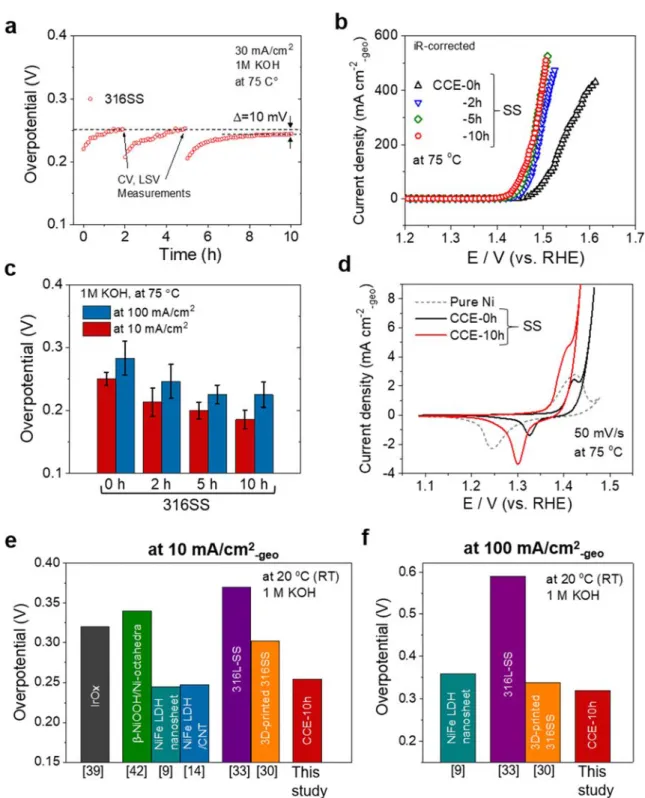
the SS samples after electrolysis for x h (x = 0, 1, 2, 5, and 10) are denoted as CCE-xh. As shown in Figure 1a, the overpotentials for the OER increased during the initial stage of electrolysis (e.g., 0 to 1 h), owing to the oxygen micro-bubble evolution at the electrode surface and/or a decrease in the electroconductivity of the SS substrate through passive layer generation. Note that the OER overpotentials were rather insensitive to the CCE time (Figure 1a), and the overpotentials at the plateau regions (e.g., 1, 4, and 10 h) decreased with increasing CCE time. The OER polarization curves and overpotentials for the OER of CCE-xh at 10 and 100 mA/cm2
are shown in Figure 1b and 1c, respectively. The onset potentials shifted to the lower potential regions with an increase in the CCE times. Furthermore, the estimated overpotentials at 10 mA/cm2 (red bar) and 100 mA/cm2 (blue bar) gradually decreased with an increasing CCE time
up to 5 h and remained approximately constant for CCE-10h. As shown in Figure 1d, cyclic voltammetry (CV) of CCE-0h showed oxidation-reduction (redox) waves at 1.42 V (positive potential sweep) and 1.32 V (negative sweep), which could be ascribable to the Ni2+ (Ni(OH)2)
and Ni3+ (NiOOH) species,40 respectively. Therefore, CV demonstrated that a Ni-based
(oxy)hydroxide species was generated at the initial stage of electrolysis. In contrast, CV of the CCE-10h sample (red) showed that the oxidation peaks at approximately 1.4 V became indistinct and shifted to lower potentials relative to those of the CCE-0h (black) and pure Ni (dashed) samples. The negative-potential shifts of CV (Figure 1d) corresponded well with the lower potential shifts of the OER onset (over potential, as shown in Figure 1b). The lower
potential shift could be derived from active-site formation for OER and microstructural changes of the surface (hydro)oxide films formed on the SS substrate during CCE.
To compare the OER overpotentials with published results, the OER overpotential of CCE-10h was estimated in a 20 °C, 1 M KOH solution (Figure S4). The estimated OER overpotentials are shown in Figure 1e and 1f. Synthesized CCE-10h showed that the OER activity (overpotential at both 10 and 100 mA/cm2) surpassed the published values of Ir oxide,39
NiOOH,41 and SS samples.30, 33 Furthermore, the overpotential reached approximately the same
value for Ni-Fe LDH, which is one of the best OER catalysts.9, 14 Furthermore, the OER current
density of CCE-10h was greater than 400 mA/cm2, which is the appropriate electrolysis current
density for practical AWE systems.4 Moreover, approximately the same polarization curves
were obtained for several repeated electrochemical measurements, indicating the high structural stability of the synthesized CCE-5h and CCE-10h against vigorous oxygen microbubble evolution on the anode surface, which could cause a serious problem in a practical AWE process,3 i.e., detachment of the OER catalyst materials.27-29 For practical use of an SS-related
anode in the AWE process, maintaining nanofiber-like Ni-Fe hydroxide layers during electrolysis at a higher current density (> 400 mA/cm2) is required4, and synthesized CCE-5h
and CCE-10h satisfied these requirements.
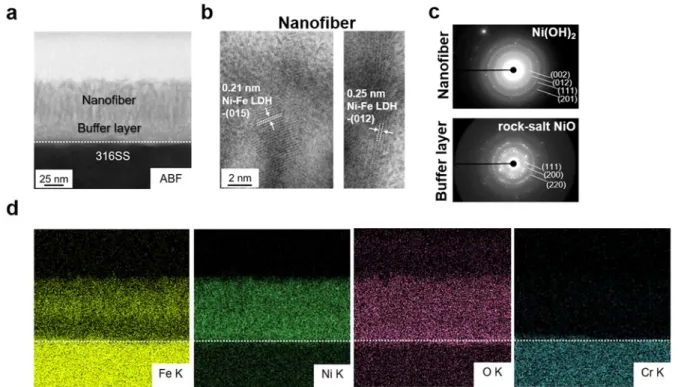
To clarify the nano-structural requirements for the active OER electrocatalysts of the CCE-xh samples, electrolysis-induced structural changes were investigated using cross-sectional STEM. The results are shown in Figure 2. For the polished SS substrate surface (before electrolysis, as shown in Figure 2a), a passivation film composed of Fe and Cr oxide with a thickness of approximately 5 nm (EDS line profiles shown in Figure S1) appeared.42 For
CCE-0h (immediately after the first OER polarization curve measurements at 75 °C), particle- and rod-like nanostructures appeared on the 10 nm thick (hydro)oxide layers formed on the SS substrate (Figure 2b). The corresponding STEM-EDS mapping (Figure S2) showed that the particle- and rod-like nanostructures were Fe-Mn oxides, whereas the (hydro)oxide layers were
composed of Ni and Fe as the metal components. CCE-2h (Figure 2c) showed an approximately 30 nm thick surface oxide layer uniformly formed on the SS substrate. In the magnified image, specific-textured nanofibers with a diameter of ~3 nm and a length of ~25 nm were observed on the 5 nm thick buffer layers. The upper layer composed of nanofibers reached 50 nm for CCE-5h in conjunction with an increase in the fiber diameter (approximately 5 nm, as shown in Figure 2d). Furthermore, for CCE-5h, the thickness of the underlaid buffer layer, estimated to be approximately 30 nm, was located between the upper fiber layer and the SS substrate. After CCE-10h, the overall surface oxide layer thickness decreased to approximately 40 nm, accompanying aggregations of the nanofibers (Figure 2e).
The crystal structures of the surface oxide layers were investigated using high-resolution STEM observations and SAED analysis. Figure 3a and 3b shows bright-field low- and high-resolution STEM images for CCE-5h, respectively. The lattice fringes of 0.21 and 0.25 nm shown in Figure 3b correspond well with the (015) and (012) planes of Ni-Fe LDH.43 In contrast,
the SAED pattern collected for the nanofiber region of CCE-5h (dotted yellow circle in Figure 3a) corresponded to the Ni(OH)2 crystal structure44 (Figure 3c). SAED patterns were collected
from the corresponding regions of CCE-2h and -10h (Figure S6), showing that the main crystal structures of the nanofiber region were Ni(OH)2, irrespective of the CCE time. The structural
analysis results suggested that the crystal phases of Ni-Fe LDH and Ni(OH)2 (Ni-rich Ni-Fe
hydroxides) generated specific nanofiber structures. On the other hand, the SAED pattern collected from the buffer layer region demonstrated a rock-salt NiO structure.45 Kim et al.41
showed that Ni(OH)2/NiO(rock-salt)/Ni layered structures were formed through the
electrochemical oxidation of Ni octahedra nanoparticles during OER. From the high-resolution TEM images, they deduced that the NiO rock-salt layers were generated to reduce the large lattice mismatch between Ni(OH)2 and Ni and thereby stabilized the Ni(OH)2
/NiO(rock-salt)/Ni three-phase layered structures. Therefore, the oxide buffer layers on the SS substrate could release the interface strains caused by large lattice mismatches between the nanofiber
layers and SS substrate. Ni-Fe hydroxide/Ni-Fe oxide/SS heterostructures could be formed during CCE owing to the phenomena mitigating the structural misfit between the hydroxides and oxides similar to that of the Ni electrode41, because the crystal structures of hydroxide and
oxide observed for the CCE-5h samples were approximately the same as that reported for the Ni electrode41, except for the incorporation of Fe atoms.
The elemental distributions of the oxide layers were analyzed using STEM-EDS mapping for CCE-5h (Figure 3d). The mapping image showed that the main elements were Fe and Ni, while Cr was not present in the (hydro)oxide region. The mapping images for CCE-2h and -10h showed that the surface (hydro)oxide layers were also comprised of the afore-mentioned elements (Figure S7). However, the elemental distributions on the surface (hydro)oxide layers were dependent on the CCE time. Figure 4a shows changes in the distributions of Ni and Fe in the upper nanofiber and underlaid buffer layer regions as a function of the CCE-time. For the nanofiber regions, the Ni:Fe ratio of CCE-2h was approximately 7:3. The Fe gradually increased with increasing CCE time, and the Ni:Fe ratio was estimated to be 1:1 for CCE10h. Conversely, the Ni:Fe ratio of the buffer oxide layers for the CCE5h and -10h samples were approximately the same at 7:3 (that for CCE-2h was too thin to estimate the Ni:Fe ratio). The nanofiber layers increased in Fe concentration over time because the Fe dissolved in the solution from the SS substrate during CCE was incorporated into the nanofiber layers preferentially in contact with the electrolyte. However, because the buffer layers located below the nanofiber layers had minimal parts in contact with the electrolyte, there was minimal change in the composition in CCE. The chemical states at the surface regions were investigated using XPS for the CCE-xh samples (Figure S9). The surface regions of the hydroxide nanofibers for CCE-2h, -5h, and -10h were mainly composed of Ni2+ and Fe3+.
The CCE-time-dependent changes in the electrochemical surface area (ECSA) and OER overpotentials at 10 mA/cm2 normalized by ECSA are shown in Figure 4b and 4c, respectively.
supporting information (Figure S10). The estimated ECSA increased from CCE-0h (7.5 cm2)
to CCE-2h (13 cm2), owing to the formation of nanofibers. After a CCE of 5 h, the ECSA
increased to 14.5 cm2, although the ECSA of CCE-10h decreased slightly to 14 cm2. As shown
in Figure 4c, the OER overpotentials normalized by the estimated ECSAs was lowered at the initial stage of CCE and further gradually decreased during the period of 2 h to 10 h of CCE. One of the most efficient OER catalysts in an alkaline electrolyte contains Ni-Fe LDH, with Ni:Fe atomic ratios of 7:3 to 1:1.46-48 Friebel et al. demonstrated, based on their DFT
calculations8, that the enhanced OER activity of Ni-Fe LDH could be derived from the
appropriate OH adsorption energy of the Fe site in an NiOOH crystal lattice. Furthermore, Chen et al. found that local electronic structures of Ni-Fe LDH could be modulated through the strong interfacial interactions of FeOOH nanoparticles of approximately 2 nm in diameter38. Therefore,
the highly efficient OER property originated from a pronounced synergy of the Fe-species in and/or on Ni-based hydroxides nanostructure. Considering the results obtained in this study and in previous reports, we can conclude that significant decrease in the OER overpotentials at the initial stage of the CCE (~2h) should stem from generation of Ni-Fe hydroxide nanostructures on the SS substrate. On the other hand, the high OER performances of CCE-5h and CCE-10h could stem from two factors. One is enrichment of OER-active Fe sites in the upper Ni-Fe hydroxide nanofiber layers, because the ECSA-normalized OER overpotentials gradually decreased from CCE-2h to -10h. Another is structural change of Ni-Fe hydroxide nanofibers. Judging from the STEM images, CCE process gradually altered the morphology of the Ni-Fe nanofibers, suggesting that the local atomic structural changes (surface defects, vacancies, etc.) also affect the increase of OER activity.
The STEM-EDS analysis results revealed changes in the chemical compositions of the CCE-xh samples, as shown in Figure 3d, S2, and S7. For CCE-0h (Figure S2), a small amount of Mn was detected in the surface oxide precipitate. Furthermore, Cr was not present in the surface oxide layers for all CCE-xh samples, although Cr is a main element of the SS substrate.
Fe and Ni remained as metal components on the surface (hydro)oxide regions of the CCE-xh samples for greater than x = 2 h (Figure S7). From the pH-potential diagrams49 of the
corresponding metal elements, Cr, Fe, and Mn should dissolve into a solution of pH = 14 at 25 °C, whereas Ni is stable as Ni(OH)2. Considering each dissolution potential, the potentials
of Cr (0.73 V vs. the reversible hydrogen electrode (RHE)) and Mn (0.93 V vs. RHE) were lower than that of Fe (1.13 V vs. RHE). Because the average applied potential of the CCE condition was approximately 1.45 V vs. RHE (Figure 1a), the Cr and Mn included in the substrate easily dissolved into the electrolyte, remaining in the Fe-enriched surface oxide layers. Protopopoff and Marcus calculated the pH-potential diagram of a Ni-Cr-Fe trimetallic alloy system and showed that the Ni-Fe oxides could reach a stable phase at a higher potential than 0.41 V vs. RHE.50 Based on the above-mentioned electrochemical oxidation/dissolution
behaviors of each metal element, the possible electrolysis time evolutions are shown in Figure 5 for the synthesized hetero-layered nanostructures of the Ni-Fe hydroxide fiber/Ni-Fe oxide buffer layers. The passivation film of an SS substrate, which is mainly composed of Fe and Cr oxides, was removed through the first CV and polarization curve measurements, leaving the Fe-Mn oxide particles on the substrate surface (Figure 2a and S2). The Ni-rich layer (Figure S1) of the polished SS substrate was then oxidized to generate Ni-Fe hydroxides on the SS substrate. Simultaneously, the Fe-Mn oxide particles dissolved under the strong oxidation conditions during electrolysis. The surface Ni and a portion of Fe should be exposed to the electrolyte to generate Ni-Fe hydroxide and/or oxide, accompanied with an electrochemical dealloying of the Cr (Cr depletion) and most of the Fe from the SS substrate. As shown in Figure S11, CCE on the pure Ni substrate under the same conditions (30 mA/cm2 for 2 h at
75 °C) generated only nanoparticles and an ultrathin film of Ni hydroxide. Thus, nanofiber-like Ni-Fe hydroxide was generated by CCE of the SS substrate owing to the simultaneous electrochemical dealloying of Cr and Fe. Oxygen micro-bubbles generated on the sample surfaces under the electrolysis conditions (30 mA/cm2 at 75 °C) should also correlate with the
generated hetero-layered nanostructures of the hydroxides. The vigorous oxygen micro-bubbles on the growing surface (Ni-Fe hydroxides) should provide inhomogeneous growth of the hydroxide layers at the topmost surface, creating nanofiber-like hydroxides. The hetero-layered nanostructures (Figure 2) and elemental distributions (Figure S7) changed depending on the CCE time. With an increase in the CCE time from 2 to 5 h, the nanofiber and buffer layer thicknesses increased, owing to a further growth of the hetero-layer structures of Ni-Fe hydroxide and oxide. The prolonged CCE of 10 h decreased the overall hetero-layer thickness and densified the nanofiber layer. The results suggested that the diffusion paths of Ni and Fe from the underlaid buffer layer and/or SS substrate to the growing topmost surface were limited by the densification of the nanofiber layer. The nano-structural changes for CCE-10h should come from the limited supplies of the SS substrate elements. The densification should decrease the electrochemical surface area (Figure 4b). However, Fe was enriched in the upper Ni-Fe hydroxide layer, maintaining the overpotential of that of CCE-5h, which had a slightly larger surface area than that of CCE-10h.
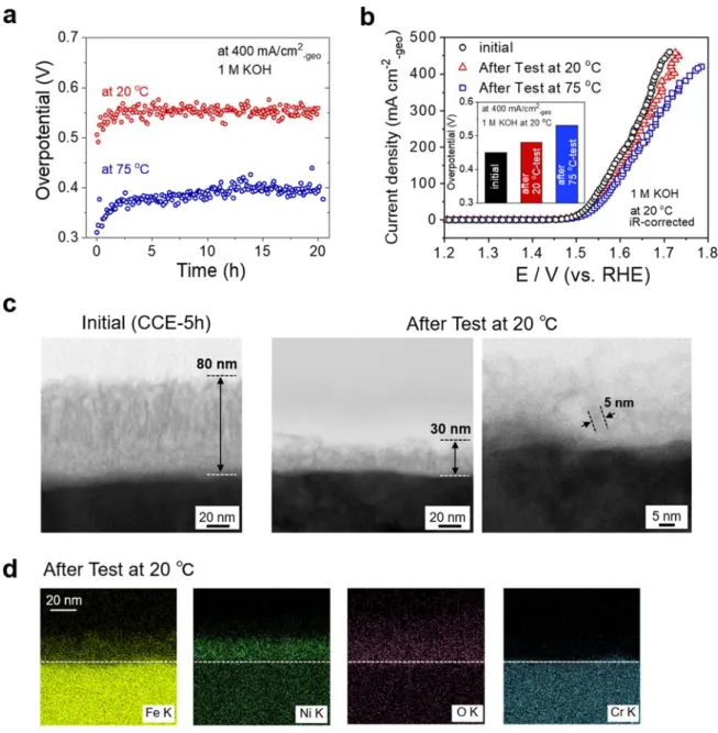
Finally, a durability test of the Ni-Fe hydroxide/oxide formed SS was conducted to evaluate its potential as an AWE anode. Figure 6a shows the chronoamperometric curves of the CCE-5h samples recorded at 400 mA/cm2 in a 1.0 M KOH solution at 20 and 75 °C. The OER
overpotentials at 400 mA/cm2 were stable for 20 h at 20 and 75 °C, except for the initial stage
up to ca. 2.5 h. The polarization curves recorded at 20 °C before and after the durability test in the 20 and 75 °C solutions are shown in Figure 6b. The overpotentials at 400 mA/cm2 estimated
from the polarization curves are also shown in the insets. The overpotential increase after the test at 20 and 75 °C was 30 and 80 mV, respectively, suggesting that electrolysis at the higher temperature deteriorated the surface electrocatalyst layer. Figure 6c shows the cross-sectional STEM images of CCE-5h before and after the durability test at 400 mA/cm2 in the 20 °C
solution. The nanofiber structures with a ca. 5 nm diameter remained on the SS substrate even after the test. However, the total thickness decreased to ca. 30 nm, and the oxide-buffer-layers
became unclear. Furthermore, the nanofiber layer was sparse relative to the initial CCE-5h. From STEM-EDS mapping (Figure 6d), Ni and Fe were present in the nanofiber regions. The EDS-composition analysis (Table S3) showed that the Ni:Fe ratio after the test was approximately 6:4, which was the same as that of the initial CCE-5h. Therefore, the overpotential increase after the durability test was owing to a decrease in the surface area from dissolution and/or detachment of parts of the nanofiber under the high anodic potentials and vigorous oxygen bubble formation. While parts of the nanofiber were removed, CCE-5h achieved stable electrolysis at 400 mA/cm2 and 20 and 75 °C . Although a more durable catalyst
layer should be developed under a real AWE operating time (> 50,000 h)4, the results obtained
in this study demonstrated the Ni-Fe hydroxide/oxide formed SS electrode is a promising material that could be used for practical AWE anodes.
3. CONCLUSIONS
Hetero-layered nanostructures of an Ni-Fe hydroxide nanofiber/Ni-Fe oxide buffer were synthesized on a 316SS substrate through a simple electrolysis process, i.e., a constant current density of 30 mA/cm2 in 1.0 M KOH at 75 °C . The cross-sectional STEM-EDS observations
revealed that Ni-Fe hydroxide nanofibers were generated on the underlaid Ni-rich Ni-Fe oxide buffer layers of the SS substrate at the initial stage of electrolysis (2 h). The hetero-structured layers grew with an increase in the electrolysis time up to 5 h, and further electrolysis (10 h) resulted in densification of the upper layer nanofiber structures. The OER overpotentials at 10 mA/cm2 for the hetero-layered nanostructures evaluated for CCE-5h and -10h were
approximately the same, 254 mV at 20 °C, and the estimated value at 20 °C outperformed standard OER catalysts, e.g., Ir oxide. An overpotential of reported Ni-Fe LDH catalysts was obtained. Furthermore, the OER performance surpassed the powder-based Ni-Fe LDH catalysts at high current density regions greater than 100 mA/cm2. Moreover, for the CCE-5h samples,
condition at 400 mA/cm2 in a 20 and 75 °C solution. This study demonstrated that a simple
method, i.e., electrolysis of the SS substrate, could be used to synthesize highly OER-active Ni-Fe hydroxide/oxides with hetero-layered nanostructures on a substrate and that electrolysis could be applicable for novel energy material developments for nano-structural controls, such as electrochemical capacitors and secondary battery electrodes.
4. EXPERIMENTAL SECTION
Materials
316 SS (ø = 5 mm, t = 4 mm; Nilako Co.) was used as the substrate for electrolysis. The SS surface was pre-polished using emery paper (#800, #1200, and #2000) and alumina paste (1 μm, 0.3 μm, and 0.05 μm) and then washed with ultrapure water and acetone prior to electrochemical treatments. Pure Ni and Fe (99.99 %, Nilako Co., ø = 5 mm, t = 4 mm) substrates were used as reference electrolysis substrates after applying the same pre-processing procedures.
Electrochemical Measurements
A potentio-galvanostat (PGSTAT128A, Autolab) equipped with an impedance module (FRA32A) and a rotating disk electrode (RDE) (WaveVortex 10, Pine Instrument) were used for the electrochemical treatments and OER activity evaluations of the electrolysis-synthesized SS samples. A water-jacket containing a glass-made cell, Pt-mesh, and Hg/HgO (1 M KOH) were employed as the EC cell, counter electrode, and reference electrode, respectively. Here, 1.0 M KOH was prepared using a 99.99 % KOH pellet (Semiconductor grade, Aldrich) and ultra-pure water (Milli-Q). The prepared electrolyte was purged with N2. After the electrodes
were attached to the RDE tip (E5TQ, Pine Instrument), the electrode surfaces were forged under electrochemical oxidation/reduction cycles between −0.3 and 1.0 V, and cyclic voltammetry was then conducted at a scan rate of 50 mV/s. The OER polarization curves were measured at
5 mV/s with a disc rotation rate of 1600 rpm. The temperature-dependent polarization curves presented the RHE, considering the experimentally estimated potential difference between the Hg/HgO electrode and RHE at each solution temperature. All OER polarization curves were corrected using 90% iR compensation. The electrochemical treatments and OER activity evaluations were conducted at electrolyte temperatures of 20 °C and 75 °C. Chronopotentiometry at a constant current density of 30 mA/cm2 was adopted for the surface
treatment of the substrate. The electrochemical stability was examined by conducting chronopotentiometry at a constant current density of 400 mA/cm2 for 20 °C and 75 °C solutions.
The solution resistance (Rs) was measured based on the ac impedance spectra, which were
applied at frequencies ranging from 10 kHz to 100 mHz at 1.45 V (vs. RHE) (Figure S4). The electrochemical surface areas were estimated based on the electrochemical double-layer (EDL) capacitances measured from the cyclic voltammograms in non-faradaic potential regions (0.83−0.93 V vs. RHE). General specific EDL capacitance values of 0.040 mF cm−2 in 1.0 M
NaOH were used.39
Structural Analysis
The surface nanostructures of the electrochemically treated SS substrates under various conditions were observed using STEM-EDS (ARM200F, JEOL) after a pre-processing of the samples using a focused ion beam (FIB; JIB-4600F, JEOL). The surface chemical bonding states of the samples were analyzed using XPS (Theta Probe, ThermoFisher Scientific) with a monochromatized Al X-ray source.
ASSOCIATED CONTENT
Supporting Information
Additional details on the structural analysis, electrochemical results, and reference data for the Ni electrodes. This material is available free of charge via the Internet at http://pubs.acs.org.
AUTHOR INFORMATION Corresponding Author
*E-mail: [email protected]
Notes
The authors declare no competing financial interest.
ACKNOWLEDGMENTS
This study was partly supported by JSPS KAKENHI, Grant Number 18H01741, Toyota Mobility Foundation Hydrogen Initiative, and Yazaki Memorial Foundation for Science and Technology (N.T.). The authors would also like to thank K. Kobayashi and M. Tanno for the STEM-EDS observations and N. Akao and Y. Ohira for the XPS measurements.
REFERENCES
(1) Seh, Z. W.; Kibsgaard, J.; Dickens, C. F.; Chorkendorff, I.; Nørskov, J. K.; Jaramillo, T. F. Combining Theory and Experiment in Electrocatalysis: Insights into Materials Design. Science 2017, 355, 1-12.
(2) Schmidt, O.; Gambhir, A.; Staffell, I.; Hawkes, A.; Nelson, J.; Few, S. Future Cost and Performance of Water Electrolysis: An Expert Elicitation Study. Int. J. Hydrog. Energy 2017, 42, 30470-30492.
(3) Schalenbach, M.; Tjarks, G.; Carmo, M.; Lueke, W.; Mueller, M.; Stolten, D. Acidic or Alkaline? Towards a New Perspective on the Efficiency of Water Electrolysis. J. Electrochem.
Soc. 2016, 163, F3197-F3208.
(4) David, M.; Ocampo-Martínez, C.; Sánchez-Peña, R. Advances in Alkaline Water Electrolyzers: A Review. J. Energy Storage 2019, 23, 392-403.
(5) Dincer, I. Green Methods for Hydrogen Production. Int. J. Hydrog. Energy 2012, 37, 1954-1971.
(6) Uchino, Y.; Kobayashi, T.; Hasegawa, S.; Nagashima, I.; Sunada, Y.; Manabe, A.; Nishiki, Y.; Mitsushima, S. Relationship between the Redox Reactions on a Bipolar Plate and Reverse Current after Alkaline Water Electrolysis. Electrocatalysis 2018, 9, 67-74.
(7) He, T.; Kar, M.; McDaniel, N. D.; Randolph, B. B., Electrochemical Hydrogen Production. In Springer Handbook of Electrochemical Energy, Breitkopf, C.; Swider-Lyons, K., Eds. Springer: Berlin, 2017; Vol. 1, pp 897-940.
(8) Friebel, D.; Louie, M. W.; Bajdich, M.; Sanwald, K. E.; Cai, Y.; Wise, A. M.; Cheng, M.-J.; Sokaras, D.; Weng, T.-C.; Alonso-Mori, R.; Davis, R. C.; Bargar, J. R.; Nørskov, J. K.; Nilsson, A.; Bell, A. T. Identification of Highly Active Fe Sites in (Ni,Fe)Ooh for Electrocatalytic Water Splitting. J. Am. Chem. Soc. 2015, 137, 1305-1313.
(9) Zhou, Q.; Chen, Y.; Zhao, G.; Lin, Y.; Yu, Z.; Xu, X.; Wang, X.; Liu, H. K.; Sun, W.; Dou, S. X. Active-Site-Enriched Iron-Doped Nickel/Cobalt Hydroxide Nanosheets for Enhanced Oxygen Evolution Reaction. ACS Catal. 2018, 8, 5382-5390.
(10) Xu, D.; Stevens, M. B.; Rui, Y.; DeLuca, G.; Boettcher, S. W.; Reichmanis, E.; Li, Y.; Zhang, Q.; Wang, H. The Role of Cr Doping in NiFe Oxide/(Oxy)Hydroxide Electrocatalysts for Oxygen Evolution. Electrochim. Acta 2018, 265, 10-18.
(11) Zhan, Y.; Du, G.; Yang, S.; Xu, C.; Lu, M.; Liu, Z.; Lee, J. Y. Development of Cobalt Hydroxide as a Bifunctional Catalyst for Oxygen Electrocatalysis in Alkaline Solution. ACS
Appl. Mater. 2015, 7, 12930-12936.
(12) Burke, M. S.; Kast, M. G.; Trotochaud, L.; Smith, A. M.; Boettcher, S. W. Cobalt–Iron (Oxy)Hydroxide Oxygen Evolution Electrocatalysts: The Role of Structure and Composition on Activity, Stability, and Mechanism. J. Am. Chem. Soc. 2015, 137, 3638-3648.
(13) Görlin, M.; Chernev, P.; Paciok, P.; Tai, C.-W.; Ferreira de Araújo, J.; Reier, T.; Heggen, M.; Dunin-Borkowski, R.; Strasser, P.; Dau, H. Formation of Unexpectedly Active Ni–Fe
Oxygen Evolution Electrocatalysts by Physically Mixing Ni and Fe Oxyhydroxides. Chem.
Commun. 2019, 55, 818-821.
(14) Gong, M.; Li, Y.; Wang, H.; Liang, Y.; Wu, J. Z.; Zhou, J.; Wang, J.; Regier, T.; Wei, F.; Dai, H. An Advanced Ni–Fe Layered Double Hydroxide Electrocatalyst for Water Oxidation.
J. Am. Chem. Soc. 2013, 135, 8452-8455.
(15) Xu, W.; Lyu, F.; Bai, Y.; Gao, A.; Feng, J.; Cai, Z.; Yin, Y. Porous Cobalt Oxide Nanoplates Enriched with Oxygen Vacancies for Oxygen Evolution Reaction. Nano Energy 2018, 43, 110-116.
(16) Grimaud, A.; Diaz-Morales, O.; Han, B.; Hong, W. T.; Lee, Y.-L.; Giordano, L.; Stoerzinger, K. A.; Koper, M. T. M.; Shao-Horn, Y. Activating Lattice Oxygen Redox Reactions in Metal Oxides to Catalyse Oxygen Evolution. Nat. Chem. 2017, 9, 457-465. (17) Chen, G.; Zhou, W.; Guan, D.; Sunarso, J.; Zhu, Y.; Hu, X.; Zhang, W.; Shao, Z. Two Orders of Magnitude Enhancement in Oxygen Evolution Reactivity on Amorphous Ba0.5Sr0.5Co0.8Fe0.2O3 Nanofilms with Tunable Oxidation State. Sci. Adv. 2017, 3.
(18) Strickler, A. L.; Escudero-Escribano, M. a.; Jaramillo, T. F. Core–Shell Au@Metal-Oxide Nanoparticle Electrocatalysts for Enhanced Oxygen Evolution. Nano Lett. 2017, 17, 6040-6046. (19) Zhu, Y.; Liu, X.; Jin, S.; Chen, H.; Lee, W.; Liu, M.; Chen, Y. Anionic Defect Engineering of Transition Metal Oxides for Oxygen Reduction and Evolution Reactions. J. Mater. Chem. A 2019, 7, 5875-5897.
(20) Cai, P.; Huang, J.; Chen, J.; Wen, Z. Oxygen-Containing Amorphous Cobalt Sulfide Porous Nanocubes as High-Activity Electrocatalysts for the Oxygen Evolution Reaction in an Alkaline/Neutral Medium. Angew. Chem. Int. Ed. 2017, 56, 4858-4861.
(21) Xuan, C.; Lei, W.; Wang, J.; Zhao, T.; Lai, C.; Zhu, Y.; Sun, Y.; Wang, D. Sea Urchin-Like Ni–Fe Sulfide Architectures as Efficient Electrocatalysts for the Oxygen Evolution Reaction. J. Mater. Chem. A 2019, 7, 12350-12357.
(22) Kuang, Y.; Kenney, M. J.; Meng, Y.; Hung, W.-H.; Liu, Y.; Huang, J. E.; Prasanna, R.; Li, P.; Li, Y.; Wang, L.; Lin, M.-C.; McGehee, M. D.; Sun, X.; Dai, H. Solar-Driven, Highly Sustained Splitting of Seawater into Hydrogen and Oxygen Fuels. Proc. Natl. Acad. Sci. 2019, 116, 6624-6629.
(23) Anantharaj, S.; Ede, S. R.; Sakthikumar, K.; Karthick, K.; Mishra, S.; Kundu, S. Recent Trends and Perspectives in Electrochemical Water Splitting with an Emphasis on Sulfide, Selenide, and Phosphide Catalysts of Fe, Co, and Ni: A Review. ACS Catal. 2016, 6, 8069-8097.
(24) Swesi, A. T.; Masud, J.; Nath, M. Nickel Selenide as a High-Efficiency Catalyst for Oxygen Evolution Reaction. Energ. Environ. Sci. 2016, 9, 1771-1782.
(25) Fang, G.; Wang, Q.; Zhou, J.; Lei, Y.; Chen, Z.; Wang, Z.; Pan, A.; Liang, S. Metal Organic Framework-Templated Synthesis of Bimetallic Selenides with Rich Phase Boundaries for Sodium-Ion Storage and Oxygen Evolution Reaction. ACS Nano 2019, 13, 5635-5645.
(26) Cao, X.; Johnson, E.; Nath, M. Expanding Multinary Selenide Based High-Efficiency Oxygen Evolution Electrocatalysts through Combinatorial Electrodeposition: Case Study with Fe–Cu–Co Selenides. ACS Sustain. Chem. Eng. 2019, 7, 9588-9600.
(27) Spöri, C.; Kwan, J. T. H.; Bonakdarpour, A.; Wilkinson, D. P.; Strasser, P. The Stability Challenges of Oxygen Evolving Catalysts: Towards a Common Fundamental Understanding and Mitigation of Catalyst Degradation. Angew. Chem. Int. Ed. 2017, 56, 5994-6021.
(28) Maljusch, A.; Conradi, O.; Hoch, S.; Blug, M.; Schuhmann, W. Advanced Evaluation of the Long-Term Stability of Oxygen Evolution Electrocatalysts. Anal. Chem. 2016, 88, 7597-7602.
(29) Zeradjanin, A. R.; Topalov, A. A.; Van Overmeere, Q.; Cherevko, S.; Chen, X.; Ventosa, E.; Schuhmann, W.; Mayrhofer, K. J. J. Rational Design of the Electrode Morphology for Oxygen Evolution – Enhancing the Performance for Catalytic Water Oxidation. RSC Adv. 2014, 4, 9579-9587.
(30) Huang, X.; Chang, S.; Lee, W. S. V.; Ding, J.; Xue, J. M. Three-Dimensional Printed Cellular Stainless Steel as a High-Activity Catalytic Electrode for Oxygen Evolution. J. Mater.
Chem. A 2017, 5, 18176-18182.
(31) Schäfer, H.; Beladi-Mousavi, S. M.; Walder, L.; Wollschläger, J.; Kuschel, O.; Ichilmann, S.; Sadaf, S.; Steinhart, M.; Küpper, K.; Schneider, L. Surface Oxidation of Stainless Steel: Oxygen Evolution Electrocatalysts with High Catalytic Activity. ACS Catal. 2015, 5, 2671-2680.
(32) Moureaux, F.; Stevens, P.; Toussaint, G.; Chatenet, M. Development of an Oxygen-Evolution Electrode from 316l Stainless Steel: Application to the Oxygen Oxygen-Evolution Reaction in Aqueous Lithium–Air Batteries. J. Power Sources 2013, 229, 123-132.
(33) Yu, F.; Li, F.; Sun, L. Stainless Steel as an Efficient Electrocatalyst for Water Oxidation in Alkaline Solution. Int. J. Hydrog. Energy 2016, 41, 5230-5233.
(34) Schäfer, H.; Chatenet, M. Steel: The Resurrection of a Forgotten Water-Splitting Catalyst.
ACS Energy Lett. 2018, 3, 574-591.
(35) Zhong, H.; Wang, J.; Meng, F.; Zhang, X. In Situ Activating Ubiquitous Rust Towards Low-Cost, Efficient, Free-Standing, and Recoverable Oxygen Evolution Electrodes. Angew.
Chem. Int. Ed. 2016, 55, 9937-9941.
(36) Shen, J.; Wang, M.; Zhao, L.; Jiang, J.; Liu, H.; Liu, J. Self-Supported Stainless Steel Nanocone Array Coated with a Layer of Ni–Fe Oxides/(Oxy)Hydroxides as a Highly Active and Robust Electrode for Water Oxidation. ACS Appl. Mater. 2018, 10, 8786-8796.
(37) Chen, J. S.; Ren, J.; Shalom, M.; Fellinger, T.; Antonietti, M. Stainless Steel Mesh-Supported Nis Nanosheet Array as Highly Efficient Catalyst for Oxygen Evolution Reaction.
ACS Appl. Mater. 2016, 8, 5509-5516.
(38) Chen, J.; Zheng, F.; Zhang, S.-J.; Fisher, A.; Zhou, Y.; Wang, Z.; Li, Y.; Xu, B.-B.; Li, J.-T.; Sun, S.-G. Interfacial Interaction between Feooh and Ni–Fe Ldh to Modulate the Local Electronic Structure for Enhanced Oer Electrocatalysis. ACS Catal. 2018, 8, 11342-11351.
(39) McCrory, C. C. L.; Jung, S.; Peters, J. C.; Jaramillo, T. F. Benchmarking Heterogeneous Electrocatalysts for the Oxygen Evolution Reaction. J. Am. Chem. Soc. 2013, 135, 16977-16987. (40) Vij, V.; Sultan, S.; Harzandi, A. M.; Meena, A.; Tiwari, J. N.; Lee, W.-G.; Yoon, T.; Kim, K. S. Nickel-Based Electrocatalysts for Energy-Related Applications: Oxygen Reduction, Oxygen Evolution, and Hydrogen Evolution Reactions. ACS Catal. 2017, 7, 7196-7225. (41) Kim, B.; Oh, A.; Kabiraz, M. K.; Hong, Y.; Joo, J.; Baik, H.; Choi, S.-I.; Lee, K. Niooh Exfoliation-Free Nickel Octahedra as Highly Active and Durable Electrocatalysts toward the Oxygen Evolution Reaction in an Alkaline Electrolyte. ACS Appl. Mater. 2018, 10, 10115-10122.
(42) Jiang, J.; Wang, D.; Chu, H.; Ma, H.; Liu, Y.; Gao, Y.; Shi, J.; Sun, W. The Passive Film Growth Mechanism of New Corrosion-Resistant Steel Rebar in Simulated Concrete Pore Solution: Nanometer Structure and Electrochemical Study. Materials 2017, 10, 412.
(43) Han, Y.; Liu, Z.-H.; Yang, Z.; Wang, Z.; Tang, X.; Wang, T.; Fan, L.; Ooi, K. Preparation
of Ni2+−Fe3+ Layered Double Hydroxide Material with High Crystallinity and Well-Defined
Hexagonal Shapes. Chem. Mater. 2008, 20, 360-363.
(44) E, S. P.; Danqing Liu; Lazenby, R. A.; Sloan, J.; Vidotti, M.; Unwin, P. R.; Macpherson, J. V. Electrodeposition of Nickel Hydroxide Nanoparticles on Carbon Nanotube Electrodes: Correlation of Particle Crystallography with Electrocatalytic Properties. J. Phys. Chem. C 2016, 120, 16059-16068.
(45) Bouessay, I.; Rougier, A.; Beaudoin, B.; Leriche, J. B. Pulsed Laser-Deposited Nickel Oxide Thin Films as Electrochromic Anodic Materials. Appl. Surf. Sci. 2002, 186, 490-495. (46) Anantharaj, S.; Ede, S. R.; Karthick, K.; Sam Sankar, S.; Sangeetha, K.; Karthik, P. E.; Kundu, S. Precision and Correctness in the Evaluation of Electrocatalytic Water Splitting: Revisiting Activity Parameters with a Critical Assessment. Energ. Environ. Sci. 2018, 11, 744-771.
(47) Görlin, M.; Gliech, M.; de Araújo, J. F.; Dresp, S.; Bergmann, A.; Strasser, P. Dynamical Changes of a Ni-Fe Oxide Water Splitting Catalyst Investigated at Different Ph. Catal. Today 2016, 262, 65-73.
(48) Dionigi, F.; Strasser, P. NiFe-Based (Oxy)Hydroxide Catalysts for Oxygen Evolution Reaction in Non-Acidic Electrolytes. Adv. Energy Mater. 2016, 6, 1600621.
(49) Pourbaix, M.; Franklin, J. A., Atlas of Electrochemical Equilibria in Aqueous Solutions; Pergamon Press: Oxford, England, 1966.
(50) Protopopoff, E.; Marcus, P. Potential-Ph Diagrams for Ni-Cr-Fe Alloys and Pb Adsorption on Ni-Cr-Fe Alloys Surfaces in Water at 25°C and High Temperature (250–350°C). J.
Figure 1. (a) Chronopotentiometry curve of SS recorded at a constant current density of 30 mA
cm−2 in 1.0 M KOH at 75 ℃. Polarization curves for OER (b) and OER overpotentials at 10
and 100 mA/cm2 of the SS as a function of the CCE times. (d) Cyclic voltammograms of the
SS of CCE-0h and -10h. Comparison of OER overpotentials at 10 mA/cm2 (e) and 100 mA/cm2
(f) estimated at 20℃ with the reported values; the corresponding reference numbers are shown below each bar graph.
Figure 2. Cross-sectional HAADF-STEM images at low (upper) and high (bottom)
magnifications of the near surface regions of the SS: (a) as-polished and after constant current density electrolysis (CCE) at 30 mA/cm2 for (b) 0 h, (c) 2 h, (d) 5 h, and (e) 10 h.
Figure 3. Cross-sectional STEM images at (a) low and (b) high resolution of the SS after CCE
of 5 h. (c) SAED patterns for 25 nm square regions (depicted in orange) of nanofiber and buffer layers of CCE-5h. (d) Corresponding STEM-EDS mappings of CCE-5h.
Figure 4. Changes in metal compositions of Ni and Fe for the (a) nanofiber and buffer layers,
(b) the estimated ECSAs, and (c) ECSA-normalized OER overpotentials at 10 mA/cm2
-ECSA as
Figure 5. Schematic of time evolutions of the hetero-layered nanostructures generated on an
Figure 6. Results of durability test of CCE-5h. (a) Chronopotentiometry curves recorded at a
constant current density of 400 mA cm−2 in 1.0 M KOH both at 20 and 75 ℃. (b)
Cross-sectional HAADF-STEM images of CCE-5h before and after the durability test at 20 ℃. (d) STEM-EDS mappings of CCE-5h after the durability test at 20 ℃.