Redundant SAR ADC Algorithms for Reliability Based on Number Theory
Y. Kobayashi, T. Arafune , S. Shibuya H. Kobayashi, H. Arai
Nov. 17-18, 2016
ART Workshop
Gunma University
Outline
• Objective
• SAR ADC
• SAR ADC Redundancy Design
• Proposed SAR Algorithm Using Fibonacci Sequence
Fibonacci Sequence and Golden Ratio
Fibonacci Weighted SAR ADC
DAC Settling Time
• Realization of Fibonacci DAC
• Conclusion
Outline
• Objective
• SAR ADC
• SAR ADC Redundancy Design
• Proposed SAR Algorithm Using Fibonacci Sequence
Fibonacci Sequence and Golden Ratio
Fibonacci Weighted SAR ADC
DAC Settling Time
• Realization of Fibonacci DAC
• Conclusion
Presentation Objective
We show here
redundancy design example for reliability.
We hope that this stimulates
automotive reliability & test engineers
Research Objective
• Development of
Reliable & High-speed SAR ADC
• Redundancy search algorithm design with Number Theory
Objective
Our Approach
SAR ADC : Successive Approximation Register ADC Golden ratio
Silver ratio
Today’s talk
Outline
• Objective
• SAR ADC
• SAR ADC Redundancy Design
• Proposed SAR Algorithm Using Fibonacci Sequence
Fibonacci Sequence and Golden Ratio
Fibonacci Weighted SAR ADC
DAC Settling Time
• Realization of Fibonacci DAC
• Conclusion
Research Background
Automotive Electronics are in spotlight
High-speed, Reliable
“SAR ADC” in microcontroller is needed
Redundancy design for error correction
Design issues
SAR ADC Configuration
Balance Scale
Weight Object
Generally use binary weight (1 , 2 , 4 , 8 , 16 , 32, 64 …)
Based on
Principle of Balance
1 2 4
1st 2 n d 3rd 4th 5th
1 6 8 4 2 1
3 1 3 1
3 0 3 0
2 9 2 9
2 8 2 8
2 7 2 7
2 6 2 6
2 5 2 5
2 4 2 4
2 3 2 3
2 2 2 2
2 1 2 1
2 0 2 0
1 9 1 9
1 8 1 8
1 7 1 7
1 6 1 6
1 5 1 5
1 4 1 4
1 3 1 3
1 2 1 2
1 1 1 1
1 0 1 0
9 9
8 8
7 7
6 6
5 5
4 4
3 3
2 2
1 1
0 0
Step Weight p(k)
Level
output
Binary Search SAR ADC Operation
5bit-5step SAR ADC
Analog Input:7.3 V
Binary weight :
16, 8, 4, 2, 1
Left? Right?
1st 2 n d 3rd 4th 5th
1 6 8 4 2 1
3 1 3 1
3 0 3 0
2 9 2 9
2 8 2 8
2 7 2 7
2 6 2 6
2 5 2 5
2 4 2 4
2 3 2 3
2 2 2 2
2 1 2 1
2 0 2 0
1 9 1 9
1 8 1 8
1 7 1 7
1 6 1 6
1 5 1 5
1 4 1 4
1 3 1 3
1 2 1 2
1 1 1 1
1 0 1 0
9 9
8 8
7 7
6 6
5 5
4 4
3 3
2 2
1 1
0 0
Step Weight p(k)
Level
output
Binary Search SAR ADC Operation
5bit-5step SAR ADC
Analog Input:7.3 V
Binary weight :
8, 4, 2, 1
16
7.3
Down!
Right
0
Binary Search SAR ADC Operation
1st 2 n d 3rd 4th 5th
1 6 8 4 2 1
3 1 3 1
3 0 3 0
2 9 2 9
2 8 2 8
2 7 2 7
2 6 2 6
2 5 2 5
2 4 2 4
2 3 2 3
2 2 2 2
2 1 2 1
2 0 2 0
1 9 1 9
1 8 1 8
1 7 1 7
1 6 1 6
1 5 1 5
1 4 1 4
1 3 1 3
1 2 1 2
1 1 1 1
1 0 1 0
9 9
8 8
7 7
6 6
5 5
4 4
3 3
2 2
1 1
0 0
Step Weight p(k)
Level
output
5bit-5step SAR ADC
Analog Input: 7.3 V
Binary weight :
2, 1
8 4 16
7.3
UP!
Left
0
0 1
Binary Search SAR ADC Operation
1st 2 n d 3rd 4th 5th
1 6 8 4 2 1
3 1 3 1
3 0 3 0
2 9 2 9
2 8 2 8
2 7 2 7
2 6 2 6
2 5 2 5
2 4 2 4
2 3 2 3
2 2 2 2
2 1 2 1
2 0 2 0
1 9 1 9
1 8 1 8
1 7 1 7
1 6 1 6
1 5 1 5
1 4 1 4
1 3 1 3
1 2 1 2
1 1 1 1
1 0 1 0
9 9
8 8
7 7
6 6
5 5
4 4
3 3
2 2
1 1
0 0
Step Weight p(k)
Level
output
5bit-5step SAR ADC
Analog Input: 7.3 V
Binary weight :
1
16 2 8
4 7.3
Balance 0 0 1 1 1
7.3⇒00111⇒7
16 − 8 − 4 − 2 − 1 + 0.5 − 0.5 =
7
Outline
• Objective
• SAR ADC
• SAR ADC Redundancy Design
• Proposed SAR Algorithm Using Fibonacci Sequence
Fibonacci Sequence and Golden Ratio
Fibonacci Weighted SAR ADC
DAC Settling Time
• Realization of Fibonacci DAC
• Conclusion
1st 2 n d 3rd 4th 5th 6th
1 6 1 0 6 3 2 1
3 1 3 1
3 0 3 0
2 9 2 9
2 8 2 8
2 7 2 7
2 6 2 6
2 5 2 5
2 4 2 4
2 3 2 3
2 2 2 2
2 1 2 1
2 0 2 0
1 9 1 9
1 8 1 8
1 7 1 7
1 6 1 6
1 5 1 5
1 4 1 4
1 3 1 3
1 2 1 2
1 1 1 1
1 0 1 0
9 9
8 8
7 7
6 6
5 5
4 4
3 3
2 2
1 1
0 0
Step output
Weight p(k)
Level
q(1)
q(2)
q(3)
SAR ADC Redundancy Design
Redundancy
Surplus, Extra
Enable digital error correction!
Using time redundancy
Increase comparison steps
Change reference to
voltages Extra
Non-binary
q(k):k-th step
correctable range
1 st 2 n d 3 rd 4 th 5 th 6 th
1 6 1 0 6 3 2 1
3 1 3 1
3 0 3 0
2 9 2 9
2 8 2 8
2 7 2 7
2 6 2 6
2 5 2 5
2 4 2 4
2 3 2 3
2 2 2 2
2 1 2 1
2 0 2 0
1 9 1 9
1 8 1 8
1 7 1 7
1 6 1 6
1 5 1 5
1 4 1 4
1 3 1 3
1 2 1 2
1 1 1 1
1 0 1 0
9 9
8 8
7 7
6 6
5 5
4 4
3 3
2 2
1 1
0 0
Step
Level
We igh t p( k) ou tpu t
Redundancy Design Operation(No Error)
Analog input:6.3
Redundant weight :
16, 10, 6, 3, 2, 1 5bit-6step SAR ADC
6.3⇒010001⇒6
16 − 10 + 6 − 3 − 2 − 1 + 0.5 − 0.5
=
6
Correctable expression
1
0 0 0 0 1
Analog input:6.3
Redundant weight :
16, 10, 6, 3, 2, 1
1 st 2 n d 3 rd 4 th 5 th 6 th
1 6 1 0 6 3 2 1
3 1 3 1
3 0 3 0
2 9 2 9
2 8 2 8
2 7 2 7
2 6 2 6
2 5 2 5
2 4 2 4
2 3 2 3
2 2 2 2
2 1 2 1
2 0 2 0
1 9 1 9
1 8 1 8
1 7 1 7
1 6 1 6
1 5 1 5
1 4 1 4
1 3 1 3
1 2 1 2
1 1 1 1
1 0 1 0
9 9
8 8
7 7
6 6
5 5
4 4
3 3
2 2
1 1
0 0
Step ou tpu t
We igh t p( k)
Level
Redundancy Design Operation(One Error)
5bit-6step SAR ADC
Error correction
High-Reliability
6.3⇒001111⇒6 Another expression One expression
16 − 10 − 6 + 3 + 2 + 1 + 0.5 − 0.5
=
6
Misjudgment
0
0 1 1 1 1 1
0 0 0 0 1
6.3⇒010001⇒6
1st 2 n d 3rd 4th 5th 6th
1 6 1 0 6 3 2 1
3 1 3 1
3 0 3 0
2 9 2 9
2 8 2 8
2 7 2 7
2 6 2 6
2 5 2 5
2 4 2 4
2 3 2 3
2 2 2 2
2 1 2 1
2 0 2 0
1 9 1 9
1 8 1 8
1 7 1 7
1 6 1 6
1 5 1 5
1 4 1 4
1 3 1 3
1 2 1 2
1 1 1 1
1 0 1 0
9 9
8 8
7 7
6 6
5 5
4 4
3 3
2 2
1 1
0 0
Step output
Weight p(k)
Level
q(1)
q(2)
q(3)
Issues of Conventional Method
Reference Voltage Selection
1. Difficult to select
proper reference voltages 2. q(k) must be fraction
Uncorrectable Range
Not effective redundancy design Good radix selection method
is needed !
Outline
• Objective
• SAR ADC
• SAR ADC Redundancy Design
• Proposed SAR Algorithm Using Fibonacci Sequence
Fibonacci Sequence and Golden Ratio
Fibonacci Weighted SAR ADC
DAC Settling Time
• Realization of Fibonacci DAC
• Conclusion
Outline
• Objective
• SAR ADC
• SAR ADC Redundancy Design
• Proposed SAR Algorithm Using Fibonacci Sequence
Fibonacci Sequence and Golden Ratio
Fibonacci Weighted SAR ADC
DAC Settling Time
• Realization of Fibonacci DAC
• Conclusion
Fibonacci Sequence
𝐹0 = 0 𝐹1 = 1
𝐹𝑛+2 = 𝐹𝑛 + 𝐹𝑛+1 (n=0,1,2…)
Fibonacci Definition
0, 1, 1, 𝟐, 3, 5, 𝟖, 13, 21, 34, 𝟓𝟓 … Property
𝑛→∞lim
𝐹𝑛
𝐹𝑛−1 = 1.618033988749895
“Golden Ratio”
Leonardo Fibonacci (Italy:1170-1250)
Example of Fibonacci number
The closest terms ratio :
(about 1.62)
Fibonacci Numbers
0, 1, 1, 2, 3, 5, 8, 13, 21, 34, 55, 89, 144…
We can see Fibonacci numbers in nature, especially in plants.
34
Golden Ratio
Golden Ratio:𝐥𝐢𝐦
𝒏→∞
𝑭𝒏
𝑭𝒏−𝟏 = 𝟏. 𝟔𝟏𝟖𝟎𝟑𝟑𝟗𝟖𝟖𝟕𝟒𝟗𝟖𝟗𝟓 = 𝝋
The most beautiful ratio
Outline
• Objective
• SAR ADC
• SAR ADC Redundancy Design
• Proposed SAR Algorithm Using Fibonacci Sequence
Fibonacci Sequence and Golden Ratio
Fibonacci Weighted SAR ADC
DAC Settling Time
• Realization of Fibonacci DAC
• Conclusion
Use of Fibonacci Sequence
Use of Binary
Change weighted
Binary Weighted (Radix=2)
Fibonacci Weighted (Radix=1.62)
Use of Fibonacci
Realize 1.62 weighted by using only integer
=Golden Ratio
Radix:Decision weighted number
5 3 2 11
Correction of Fibonacci Redundancy Design
Found out properties of two points!
1. Correctable range q(k) is
always Fibonacci number 𝑭𝑴−𝒌−𝟏. 2. q(k) is exactly in contact q(k+1)
without overlap.
Fibonacci sequence SAR ADC
Correction of Fibonacci Redundancy Design
Found out properties of two points!
1. Correctable range q(k) is
always Fibonacci number 𝑭𝑴−𝒌−𝟏. 2. q(k) is exactly in contact q(k+1)
without overlap.
Fibonacci sequence SAR ADC
1st 2 n d 3rd 4th 5th 6th 7th
16 8 5 3 2 1 1
3 3 3 2 3 1 3 0 2 9 2 8 2 7 2 6 2 5 2 4 2 3 2 2 2 1 2 0 1 9 1 8 1 7 1 6 1 5 1 4 1 3 1 2 1 1 1 0 9 8 7 6 5 4 3 2 1 0 - 1 - 2 Step Weight p(k)
Level
q(5) q(4)
q(3) q(2)
q(1)
Correction of Fibonacci Redundancy Design
Found out properties of two points!
1. Correctable range q(k) is
always Fibonacci number 𝑭𝑴−𝒌−𝟏. 2. q(k) is exactly in contact q(k+1)
without overlap.
Fibonacci sequence SAR ADC
Golden ratio covers wide input range by minimum extra comparison steps.
1st 2 n d 3rd 4th 5th 6th 7th
16 8 5 3 2 1 1
3 3 3 2 3 1 3 0 2 9 2 8 2 7 2 6 2 5 2 4 2 3 2 2 2 1 2 0 1 9 1 8 1 7 1 6 1 5 1 4 1 3 1 2 1 1 1 0 9 8 7 6 5 4 3 2 1 0 - 1 - 2 Step Weight p(k)
Level
q(5) q(4)
q(3) q(2)
q(1)
The most efficient design !
Comparison with Other Radix Methods
1st 2 n d 3rd 4th 5th 6th 7th
1 6 1 4 8 5 3 2 1
3 1 3 0 2 9 2 8 2 7 2 6 2 5 2 4 2 3 2 2 2 1 2 0 1 9 1 8 1 7 1 6 1 5 1 4 1 3 1 2 1 1 1 0 9 8 7 6 5 4 3 2 1 0 Step Weight p(k)
Level
q(1)
q(2) q(3)
q(4)
Radix=1.7
Conventional method
1st 2 n d 3rd 4th 5th 6th 7th
1 6 9 6 4 2 2 1
3 1 3 0 2 9 2 8 2 7 2 6 2 5 2 4 2 3 2 2 2 1 2 0 1 9 1 8 1 7 1 6 1 5 1 4 1 3 1 2 1 1 1 0 9 8 7 6 5 4 3 2 1 0 Step Weight p(k)
Level
q(1) q(2)
q(3) q(4)
1.55
Conventional method Proposed method
1st 2 n d 3rd 4th 5th 6th 7th
16 8 5 3 2 1 1
3 1 3 0 2 9 2 8 2 7 2 6 2 5 2 4 2 3 2 2 2 1 2 0 1 9 1 8 1 7 1 6 1 5 1 4 1 3 1 2 1 1 1 0 9 8 7 6 5 4 3 2 1 0 Step Weight p(k)
Level
q(5) q(4) q(3) q(2) q(1)
1.62
5bit SAR ADC
Radix is bigger than 1.62
separated
Radix is smaller than 1.62
overlapped
Standard !
Outline
• Objective
• SAR ADC
• SAR ADC Redundancy Design
• Proposed SAR Algorithm Using Fibonacci Sequence
Fibonacci Sequence and Golden Ratio
Fibonacci Weighted SAR ADC
DAC Settling Time
• Realization of Fibonacci DAC
• Conclusion
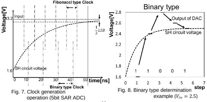
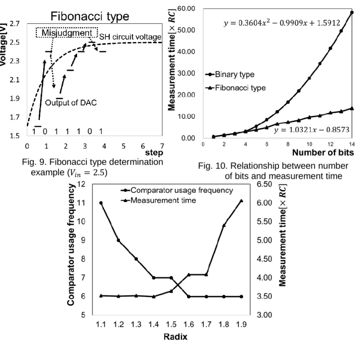
Internal DAC Output Settling Time
1st 2nd 3rd
16 8 5
31 30 29 28 27 26 25 24 23 22 21 20 19 18 17 16 15
Step
Weight p(k)
Level
Left? or Right? UP?
Down?
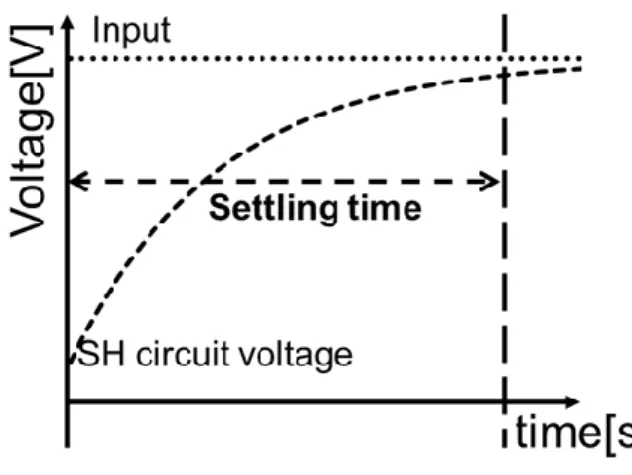
Settling Time
Transition time
from k-th step voltage to next step voltage
Comparator
Thinking!!
Internal DAC Incomplete Settling
Correctable difference
q(k)
Settling time [s]
Output of DAC [LSB]
Compared Voltage 1/2LSB
Settling Time Requirement
Error range to get correct output
Shorten!
Shorten AD Conversion time
Binary search Redundant
search
The shortest AD conversion
time !!
5bit SAR ADC
Reduction of AD Conversion Time
Conventional Redundant search
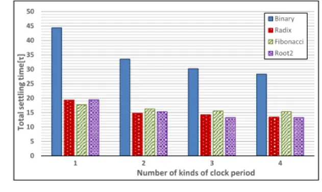
Comparison of SAR AD Conversion Time
Fibonacci the shortest AD conversion time !!
Total time [s]
Settling time at every resolution
Resolution [bit]
Conventional Redundancy
At fixed clock,
Outline
• Objective
• SAR ADC
• SAR ADC Redundancy Design
• Proposed SAR Algorithm Using Fibonacci Sequence
Fibonacci Sequence and Golden Ratio
Fibonacci Weighted SAR ADC
DAC Settling Time
• Realization of Fibonacci DAC
• Conclusion
Binary SAR ADC Configuration
Balance Scale
Weight Object
Generally use binary weight
(1 , 2 , 4 , 8 , 16 , 32, 64 …)
Fibonacci SAR ADC Configuration
Balance Scale
Weight Object
Change to Fibonacci weight
(1 , 1 , 2 , 3 , 5 , 8, 13 …)
Fibonacci SAR ADC Configuration
Balance Scale
Weight Object
Change to Fibonacci weight (1 , 1 , 2 , 3 , 5 , 8, 13 …)
Changing to
Fibonacci weight…
More complex
More large-scale than conventional.
Problem
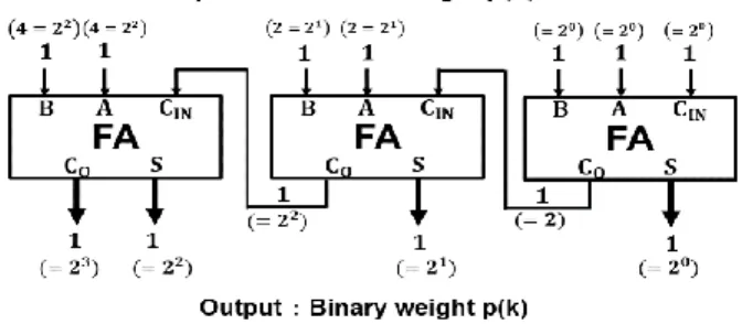
Binary and Fibonacci DACs
⇒Generate binary voltage
⇒Generate Fibonacci voltage
Change all resistors to R
R-R resistor ladder R-2R resistor ladder
Realize Fibonacci DAC by using simple circuit !
R R R
R-R resistor ladder
R-2R resistor ladder
Proposal
Binary
Principle of Fibonacci Voltage Generation
Divides current into Fibonacci ratio in each node
𝐹
𝑛+2= 𝐹
𝑛+1+ 𝐹
𝑛𝐼
𝑛+2= 𝐼
𝑛+1+ 𝐼
𝑛Principle
Proposal of R//R Fibonacci DAC
Generate
Fibonacci voltage of odd term
Generate
Fibonacci voltage of even term
Change terminal resistors to parallel resistors
R-R resistor ladder
with terminations of R//R R-R resistor ladder
Proposal
Fibonacci DAC Architecture
Odd terms
Even terms
Outline
• Objective
• SAR ADC
• SAR ADC Redundancy Design
• Proposed SAR Algorithm Using Fibonacci Sequence
Fibonacci Sequence and Golden Ratio
Fibonacci Weighted SAR ADC
DAC Settling Time
• Realization of Fibonacci DAC
• Conclusion
Propose redundant SAR ADC design methods
Get important properties by using Fibonacci sequence
Reliable
Correctable difference covers wide input range
Shortest SAR AD Conversion
Conversion time is the shortest in a fixed clock
Radix-Standard
Golden ratio 𝜑 establish radix standard
Propose beautiful DAC structures
which generate Fibonacci voltages.
Conclusion
Hope that these will contribute to automotive applications !
Appendix
Configuration of Redundancy SAR ADC
5
S/H Circuit
Thermal code decoder
Add-Register subtractor
adder
Memory(RAM)
MUX
Output Register DAC
+ + - +
1 0
25
5 5
5
5
5 5
C-array and Comparator
5 5
5
SAR ADC circuits consist of mostly digital circuit.
Store reference voltage weight p(k)
Chip of Redundancy SAR ADC
(0.18um CMOS 2.5mm x 2.5mm)
C_array
Comparator RAM
Adder
Decoder Timing Generator
Additional circuits are very small !!
Temporal vs Spatial Redundancy
● Temporal redundancy
● Spatial redundancy
SAR ADC
with 3 comparators [1]
● I have a feeling
temporal redundancy is more effective.
[1] M. Hotta, M. Kawakami, H. Kobayashi, et. al.,
"SAR ADC Architecture with Digital Error Correction", IEEJ Trans. Electrical and Electronic Eng. (Nov. 2010).
Redundancy vs Testing
● Robust design makes its testing difficult.
● Redundancy hides defects in DUT.
Testing of redundant systems is a challenge.
Silver Ratio 𝐒𝐢𝐥𝐯𝐞𝐫 𝐑𝐚𝐭𝐢𝐨 ∶ 𝟐
𝟏 = 𝟏. 𝟒𝟏𝟒 … .
Golden ratio Silver ratio
LSI Scaling vs. Silver Ratio
LSI Scaling Rule
1/ √2 1/ √2 1/ √2 1/ √2 1/ √2
Silver Ratio Weight
For 2 steps, 2 times (𝑟
2= 2)
For 1 step, 2 times (𝑟 = 2)
Peudo radix 𝟐 𝐰𝐞𝐢𝐠𝐡𝐭
×2
×1
×2
×1
×1
×2
× 𝟐
× 𝟐
× 𝟐
× 𝟐
× 𝟐
× 𝟐
“Silver ratio”
p(M) =1 p(M-1) =1 p(M-2) =1 p(M-3) =2 p(M-4) =2 p(M-5) =4 p(M-6) =4 p(M-7) =8 p(M-8) =8 p(M-9) =16 p(M-10) =16
N bit M step SAR ADC
Weights p(k)
Silver Ratio Weight SAR ADC
1st 2nd 3rd 4th 5th 6th 7th 8th
16 4 4 2 2 1 1 1
31 31
30 30
29 29
28 28
27 27
26 26
25 25
24 24
23 23
22 22
21 21
20 20
19 19
18 18
17 17
16 16
15 15
14 14
13 13
12 12
11 11
10 10
9 9
8 8
7 7
6 6
5 5
4 4
3 3
2 2
1 1
0 0
output
Level Step Weight p(k)
q(1) q(2)
q(4) q(3)
q(5) q(6)
5bit 8step SAR ADC
SAR ADC Speed Comparison
0 10 20 30 40 50
4
6
8
10
総整定時間[τ]
分解能[bit]
3
種類のクロック周期の整定時間合計値
Binary Radix Random Fibonacci Root2
For 3 kinds of clocks, the silver ratio SAR ADC is the fastest !
Speed Comparison of SAR ADC with 3 Kinds of Clocks
AD Conversion Time [τ]
Number theory for Engineering
“Number theory is
the queen of mathematics”
Carolus Fridericus Gauss
Past Number theory
Beautiful and Mysterious was NEVER practical
Current Number theory
used information communication processing good match to digital technology
Carolus Fridericus Gauss (1777-1855)
Number theory application for ADC/DAC is a frontier.
There are great chances for new discovering !
Kobayashi
Laboratory
Yutaro Kobayashi, Takuya Arafune, Shohei Shibuya, Haruo Kobayashi, Hirotaka Arai Division of Electronics and Informatics, Gunma University, Kiryu, Gunma 376-8515 Japan Abstract— This paper describes SAR ADC algorithms to
ensure reliability with possible targets for automotive applications. The SAR ADC has beneficial characteristics of low power and small chip area, and hence it is widely used, especially in automotive applications together with micro- controllers. There, digital error correction method using redundant comparison is an effective method to improve its reliability and conversion speed because it realizes correction of misjudgment at a comparator and incomplete settling of an internal DAC. Then this paper describes two effective redundancy design algorithms based on number theory: (i) The first one uses Fibonacci sequence and its property called Golden ratio Especially, several interesting properties are clarified that contribute to solve SAR ADC design problems, such as radix standard and shortening required settling time. (ii) The second one uses pseudo silver ratio (square root of 2) for the SAR ADC, which leads to simple SAR logic design and fast conversion speed in case of multiple clock period usage.
Keywords—SAR ADC, Reliability, Redundancy, Error Correction, Fibonacci Sequence, Golden Ratio, Silver Ratio
I. INTRODUCTION
UCCESSIVE approximation resistor A-D converters (SAR ADCs) are gathering attention thanks to their useful characteristics for automotive applications. Its performance improvement of conversion reliability and speed is demanded to match with high technology, and we study here about redundancy design of SAR ADCs for their realization.
Redundancy design enables digital error correction to improve SAR ADC performance [1-7]. One redundancy design method is to use a non-binary search algorithm instead of a binary search algorithm. There, extra comparison steps and a non-binary weighted DAC are needed for a redundant SAR ADC and we have to determine its non-binary weighted values.
Generally, their values are determined using a non-binary radix method or selected flexibly by the SAR ADC designer.
However the efficient and systematic redundant SAR ADC algorithm design method has not been studied well yet.
In this paper, we discuss two methods to design redundant SAR algorithms based on number theory, i.e., (i) Fibonacci sequence (or golden ratio) and (ii) Pseudo silver ratio methods.
Then we obtain well-balanced non-binary weight values.
This paper is organized as follows: Section II overviews SAR ADCs, and Section III outlines their redundancy design.
Section IV presents our first method of redundancy design using Fibonacci sequence and Section V shows the incomplete settling problem of an internal DAC inside the SAR ADC.
Section VI shows our second method of redundancy design using pseudo-silver-ratio for the SAR ADC using multiple
clock periods. Section VII provides conclusion.
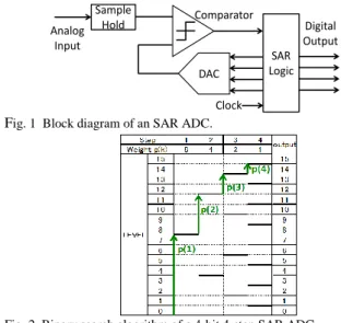
II. OVERVIEW OF SARADC
The SAR ADC consists of a sample-and-hold circuit, a comparator, a DAC, an SAR logic and a timing generator as shown in Fig. 1. Conversion of the SAR ADC is based on principle of balance and generally it uses the binary search algorithm. Firstly, the sample-and-hold circuit samples analog
input voltage regularly. Secondly, the comparator compares the sampled voltage and the reference voltage which is generated by the DAC and decides 1-bit digital output. Thirdly, SAR logic provides digital code for the DAC input based on the comparator output. The sampled input voltage and the updated DAC output voltage are compared by the comparator. These operations are repeated and finally SAR ADC obtains the whole digital output.
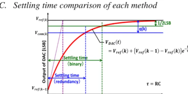
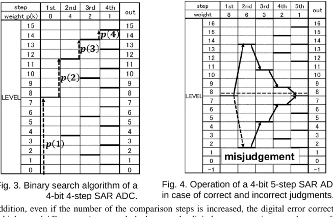
Fig. 2 shows the binary search algorithm of a 4-bit SAR ADC.
The bold line in Fig. 2 indicates the reference voltage value to compare with the sampled input voltage at each step. Their
Redundant SAR ADC Algorithms for Reliability Based on Number Theory
S
Fig. 1 Block diagram of an SAR ADC.
Sample Hold
DAC Analog
Input
Comparator
Clock
Digital Output SAR Logic
Fig. 2 Binary search algorithm of a 4-bit 4-step SAR ADC.
Fig. 3 Operation of a 4-bit 5-step SAR ADC in case of correct and incorrect judgments.
values are calculated by either sum or difference between the last step reference voltage and the weighted voltage p(k) of each step as shown in Fig. 2. The comparator outputs 1 if the input voltage is larger than the reference voltage; otherwise it outputs 0. Then we obtain the digital output at each step.
Usually, p(k) which is defined as a reference voltage weight of the DAC is a binary weighted value because the binary search algorithm is efficient. However, in reality, there is possibility of comparator misjudgment due to DAC incomplete settling and sample-and-hold circuit incomplete settling as well as noise. In the binary weighted SAR ADC, one misjudgment of the comparator leads to incorrect output and low reliability.
Hence this paper investigates redundancy design of the SAR ADC to enable digital error correction for misjudgment of the comparator.
III. REDUNDANCY DESIGN OF SARADC
Redundancy design is a technique to improve circuit and system performance. In the SAR ADC, redundancy design method adding extra comparison is often utilized [1-7]. This method changes binary weights to non-binary weights for the DAC that makes reference voltage and realizes digital error correction with redundancy property.
Fig. 3 shows an example of two redundant search operations of a 4-bit 5-step SAR ADC. There, the input voltage is 8.6- LSBs and the reference voltage weights p(k) are 1, 2, 3, 6 and 8. The one operation (solid arrows) assumes that the comparison is correct, whereas the other (dotted arrows) assumes that it is incorrect. However both obtain the correct digital output of 8 by digital error correction. In the 4-bit 5-step SAR ADC as shown in Fig. 3, there are 25 comparison patterns against 24 output patterns. In other words, a given output level can be expressed by multiple comparison patterns. Therefore even if comparator decision is wrong at some steps, the correct ADC output may be obtained. This is the basic principle of the digital error correction. In addition, even if the number of the comparison steps is increased, the digital error correction enables high-speed AD conversion as a whole, because the digital error correction can take care of the DAC incomplete settling [1-7]; thus redundancy design has potential for reliable and high-speed SAR AD conversion.
A. Generalization of redundant SAR ADC design
We generalize SAR ADC redundancy design from using some equations [3]. If we realize an N-bit resolution SAR ADC by M-step comparison (M ≥ N), the reference voltage Vref(k) at k-th step and ADC output Dout are defined by (1) and (2), respectively. Here k = 1, 2, 3, 4, … , M and p(k) is the reference voltage weight value for addition to (or subtraction from) the DAC input in the previous step. Moreover, each d(k) is decided by the comparator output. If the comparator digital output at k- th step is 1, then d(k) = 1, and if the comparator digital output at k-th step is 0, then d(k) = -1. Furthermore d(0) = 1.
. ) ( ) 1 ( )
( k1
ref k i d i p i
V (1)
We can also define “the redundancy at k-th step q(k)” as (2).
M
k
i p i
k p k
q( ) ( 1) 1 2 ( ). (2)
Here q(k) indicates correctable difference between the input voltage and the reference voltage at k-th step[3]. Even if the comparator result is wrong in the k-th step, we can obtain the correct output as long as (3)is satisfied.
. ) ( )
(k Vin Vref k
q (3)
Fig. 4 shows q(k) as an example of Fig. 3. In Fig. 4, one-way arrows indicate q(k), while two-way arrows show correctable input ranges which means that these input ranges have multiple expressions. As shown in Fig. 4, since the input voltage 8.6- LSBs satisfies (3), the SAR ADC can obtain the correct output in Fig. 3. Therefore q(k) expresses the digital error correction capability. Moreover q(k) is defined by only the reference voltage weight p(k) in (2), and thus p(k) is an important parameter in the redundant SAR ADC algorithm design.
B. Conventional method to decide reference voltage weight Only reference voltage weight p(k) decides correction capability of the redundant SAR ADC; if the design of the reference voltage weight p(k) is not appropriate, the SAR ADC cannot have the maximum compensation ability. The ratio of the reference voltage weights p(k+1)/p(k) must be between 1 (unary) and 2 (binary). In conventional methods, we can obtain the k-th step reference voltage weight p(k) based on the radix r in (4). Here, N is the ADC resolution, and M is the number of the whole steps.
. )
(k rM k
p (4)
Here 1 < r < 2 and p(1) = 2N-1. We set p(1) to 2N-1 which is half of the full scale range, to make the SAR algorithm efficient.
Additionally, the total number of steps M has to satisfy (5) to enable all output level expression.
2
0
1 1 ( ).
2 M
i
N p M i (5)
We can systematically decide conditions for redundancy design
Fig. 4 4-bit 5-step SAR ADC algorithm and definition of correctable difference q(k).
1 2 3 4 5 6
8 5 3 2 1 1
16 16
15 15
14 14
13 13
12 12
11 11
10 10
9 9
8 8
7 7
6 6
5 5
4 4
3 3
2 2
1 1
0 0
-1 -1
Step Weight p(k)
LEVEL
output
q(1) q(2)
q(3) q(4)
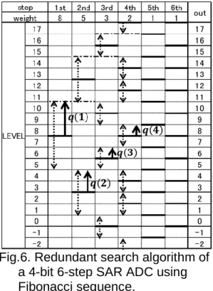
Fig. 5 Non-binary search algorithm using Fibonacci sequence of a 4-bit 6-step SAR ADC.
based on the above equations.
C. Problems of Conventional methods
Conventional methods may have some issues. First, the reference voltage weight p(k) in (5) is not an integer which is not suitable for the circuit design. Since the reference voltage weights p(k) must be integers for conversion accuracy, its rounding to an integer is needed to determine p(k). However rounding causes change of the radix and variability of the correction capability q(k), which may disturb performance improvement.
In addition, there is difficulty of an appropriate radix choice.
Fig. 3 shows an example in case of radix 1.80 and rounding.
However in Fig. 4, two-way arrows indicate that correctable input range cannot cover all input range, which means that there are some ranges that cannot be corrected. In Fig. 4, if the ADC input is not within the range of 1~3, 7~9, 13~15 LSBs, redundancy design becomes meaningless because these input ranges cannot be expressed in multiple. Thus the inappropriate selection of a radix loses redundancy design effectiveness. On the other hand, the selection of a small radix for larger values of q(k) induces an increase in the number of SAR ADC comparison steps and hence conversion time. In this way, there is a trade-off between correction capability and conversion speed, and the SAR ADC designer is forced to search a radix that is the most suitable for SAR ADC; these are causes of design difficulty.
D. Time redundancy and circuit redundancy
In this paper, we consider the time redundancy or step redundancy for the SAR ADC. Also circuit redundancy may be possible. For example, we previously investigated to use three comparators in the SAR ADC and there digital error correction was incorporated for high reliability and fast conversion [8].
However, we consider from our experiences that the time redundancy would be more effective, especially for low power.
IV. REDUNDANCY DESIGN USING FIBONACCI SEQUENCE Here, we propose a redundancy design method using Fibonacci sequence.
A. Fibonacci sequence
Fibonacci sequence is defined with a recurrence formula as shown in (6), where n in (6) is an integer greater than or equal to 0. It was presented in 1202 by Leonardo Fibonacci [9].
1.
2
n n
n F F
F (6)
Here, F0 = 0 and F1 = 1. Fibonacci numbers are expressed as the following by calculating (6) :
0, 1, 1, 2, 3, 5, 8, 13, 21, 34, 55, 89, 144, 233, 377, 610, … . In short, the sum of neighboring two terms is next term. In addition, the closest terms ratio of Fibonacci sequence converges to about 1.62 as shown in (7).
𝑛→∞lim𝐹𝑛 / 𝐹𝑛−1= 1.6180339887 … = 𝜑. (7) This ratio is called “Golden ratio”, and widely recognized as the most beautiful ratio. We can find Fibonacci sequence and Golden ratio in various places such as nature and human societies, and they have many interesting properties [9].
B. Fibonacci sequence application to SAR ADC design Equation (6) indicates that Fibonacci sequence numbers are integers, and (7) indicates that the closest term ratio of Fibonacci number converges to about 1.62 called Golden ratio.
In other words, Fibonacci sequence can generate a number string at radix 1.62 with only integer terms. In general, multiplication result of an integer and a decimal fraction is a decimal fraction, nevertheless multiplication result of an integer and a decimal fraction (1.62..) is an integer in Fibonacci sequence. Therefore we can apply Fibonacci sequence to the redundancy algorithm design of the SAR ADC using effective properties of the fixed rate and integer terms.
We select the reference voltage weight p(k) by using Fibonacci sequence as shown in (8).
. )
(k FMk1
p (8)
Here, p(1) = 2N-1. In short, we set p(k) to Fibonacci number in ascending order. Since p(k) follows the property of Fibonacci sequence, the proposed method can realize radix 1.62 by using only integers. Here the total number of steps M satisfies (5).
Fig. 5 shows correctable difference in a redundant search of a 4-bit 6-step SAR ADC using Fibonacci sequence as shown in (8). One-way arrows indicate q(k) and two-way arrows show correctable input range just like in Fig. 4.
C. Discovered Properties and Effectiveness
We have discovered two interesting properties in Fig. 5 as follows:
Property 1: Correctable difference q(k) of k-th step is always Fibonacci number 𝐹𝑀−𝑘−1.
. )
(k FMk1
q (9)
Property 2: q(k) of k-th step is exactly in contact with q(k+1) of (k+1)-th step without overlap. In other words, the tips of two-way arrows of k-th step and (k+1)-th step points are exactly the same level.
The property 2 is important for design of redundant SAR ADC algorithm due to the following two reasons:
First, the property can be a standard for all redundancy designs in the viewpoints of the radix of Fibonacci sequence which is golden ratio 1.62…, and the boundary condition of q(k). Hence, we can confirm that q(k) becomes overlapped, separated or contact by using golden ratio. If the radix value is larger than the golden ratio, the redundancy is small and q(k) boundaries are separated as shown in Fig. 4. On the other hand, if the value of the radix is smaller than the golden ratio, the redundancy is large and q(k) boundaries are overlapped, which means that all input range have multiple expressions. Thus we can easily select the radix by considering the golden ratio as the standard.
Second, the redundancy design using Fibonacci sequence can be considered as the most efficient design. The property 2 indicates that q(k) covers all input range by minimum extra comparison steps. Therefore, we can realize the redundancy design without waste by only integer terms. Moreover even if we change the first step reference voltage, the property 2 holds because of (2), which means that the redundancy design using Fibonacci sequence is flexible.