INVITED PAPER Special Issue on the Past, Present, and Future of Communications Technologies in the IEICE
Radio Access Technologies for Broadband Mobile Communications
Mamoru SAWAHASHI†a),Fellow andKenichi HIGUCHI††,Member
SUMMARY This paper describes the broadband radio access tech- niques for Universal Mobile Terrestrial Systems (UMTS)/Wideband Code Division Multiple Access (W-CDMA), High-Speed Downlink Packet Ac- cess (HSDPA)/High-Speed Uplink Packet Access (HSUPA), Long Term Evolution (LTE), and LTE-Advanced. Major technical pillars are almost identical regardless of the radio access systems of the respective gener- ations. However, the key techniques that provide distinct performance improvements have changed according to the system requirements in each generation. Hence, in this paper, we focus on the key techniques associated with the system requirements. We also describe the requirements, radio access technology candidates, and challenges toward the future 5G systems.
key words: W-CDMA, HSDPA, HSUPA, LTE, LTE-Advanced, multi-access scheme, radio access technologies
1. Introduction
Commercial service of Japanese analog mobile communi- cations using multi-channel access based on a small cell structure was initiated in 1979[1]. A high-capacity urban system was launched in 1986 that introduced new techniques including receive diversity, interference detection, and si- multaneous transmission from multiple cell sites[1]. The dawn of personal wireless communications emerged through a set of user equipment (UE) or compact handset called Mi- croTAC[2]. In 1992, the Personal Digital Cellular (PDC) system was launched, which adopted 3-channel time divi- sion multiple access (TDMA) and π/4-shifted quadrature phase shift keying (QPSK) modulation. In the 1stgeneration analog cellular systems and 2nd generation digital cellular systems, 3-cell frequency reuse was adopted to avoid co- channel interference from neighboring cells. In the 1990s, the number of subscribers increased significantly along with miniaturization and a decrease in power consumption in UEs. One of the most important system requirements for the 3rd generation Wideband Code Division Multiple Access (W-CDMA) was to increase the system capacity of voice communication channels. Meanwhile, mobile Internet be- came widespread following the spread of Internet access in fixed networks. In 2001 when W-CDMA was launched, the main source of traffic changed from voice communications
Manuscript received October 17, 2016.
Manuscript revised January 27, 2017.
Manuscript publicized March 22, 2017.
†The author is with Tokyo City University, Tokyo, 158-8557 Japan.
††The author is with Tokyo University of Science, Noda-shi, 278-8510 Japan.
a) E-mail: [email protected]
DOI: 10.1587/transcom.2016PFI0015
to data including Internet and video. Hence, high-speed packet access radio interfaces called High-Speed Downlink Packet Access (HSDPA) and High-Speed Uplink Packet Ac- cess (HSUPA) were specified to support high-speed data transmission. HSDPA and HSUPA were enhancements to shared channels carrying user data. Hence, coexistence with W-CDMA was essential because common channels includ- ing control and synchronization channels of the W-CDMA radio interface were used mandatorily. Long Term Evolution (LTE) radio interfaces were specified as the 3rd Generation Partnership Project (3GPP) Release (Rel.) 8 specifications.
LTE achieves higher peak frequency efficiency, cell through- put, and cell-edge user throughput compared to HSDPA and HSUPA based on the Rel. 5 and 6 specifications, respectively.
Hence, real mobile broadband services with the peak data rate of greater than 100 Mbps are achieved. LTE-Advanced based on the Rel. 10 specifications represents enhancements to LTE and maintains full backward compatibility with LTE.
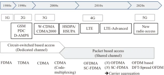
Over the past few decades, and as marked by the specifi- cation of LTE-Advanced, high capacity has become one of the most important requirements for cellular systems. This requirement can be satisfied through three approaches: ex- tending the available frequency spectra, densifying base sta- tion (BS) deployment using a small cell, and improving the spectral efficiency by introducing new radio access technolo- gies. Among these approaches, we focus on the radio access technologies in this paper. A multi-access (MA) scheme or multiplexing scheme for physical channels is very important and representative of radio access technologies. Figure 1 shows enhancements to MA schemes in cellular systems adopted over the past decades. This paper outlines the MA technologies for W-CDMA as the 3rd generation (3G) cel- lular system, LTE and as the 4th generation (4G) cellular system, and LTE-Advanced as the 5th generation (5G) cel- lular system. As shown in Fig. 1, W-CDMA achieved an increased system capacity for voice communication chan- nels using a dedicated channel. HSDPA achieved resource assignment based on scheduling using a high-speed shared channel, while HSUPA used an enhanced dedicated channel.
LTE adopts only packet-based access where radio resources are assigned based on scheduling. Orthogonal frequency division multiples access (OFDMA) and single-carrier fre- quency division multiple access (SC-FDMA) are adopted in the LTE downlink and uplink, respectively. LTE-Advanced improves performance levels using carrier aggregation (CA) based on the same MA schemes as those in LTE. Standard- ization of the radio interface of 5G cellular systems has been Copyright©2017 The Institute of Electronics, Information and Communication Engineers
Fig. 1 Enhancements to MA schemes in cellular systems.
initiated aiming at completion of the specifications in 2020.
This paper describes the broadband radio access tech- niques for UMTS/W-CDMA, HSDPA/HSUPA, LTE, and LTE-Advanced. The major technical pillars are almost iden- tical regardless of the radio access systems in the respective generations. We also describe the requirements and radio access technology candidates toward the future 5G systems.
The rest of the paper is organized as follows. Section 2 de- scribes the features of the W-CDMA air interface and key radio access technologies. Then, Sect. 3 elaborates on the key radio access technologies for HSDPA and HSUPA. Next, Sect. 4 and Sect. 5 describe the system requirements and key radio access technologies for LTE and LTE-Advanced, respectively. Section 6 describes the radio interfaces for machine-type communications (MTC) in the 3GPP speci- fications. Section 7 characterizes the system requirements, radio access technology candidates, and challenges to the fu- ture 5G cellular systems aiming at the launch of commercial service around 2020.
2. W-CDMA
2.1 W-CDMA Radio Interface[3]–[5]
In W-CDMA, one-cell frequency reuse was adopted to in- crease the system capacity of voice communication chan- nels. One-cell frequency reuse was achieved through phys- ical channel multiplexing in the code domain, and the MA interference from the own and neighboring cells was sup- pressed by the processing gain including the channel cod- ing gain as a part of spreading. Figure 2 shows the radio frame structure for the W-CDMA radio interface. One radio frame length is 10 ms, which comprises 15 slots. A 0.667- ms long slot is the time unit to perform coherent detection and closed-loop transmit power control (TPC). The chip rate after spreading is 3.84 Mcps. The transmission bandwidth after pulse shaping with a root raised-cosine roll-off filter is 5 MHz.
User data are carried by a dedicated channel called the dedicated physical channel (DPCH). The DPCH com- prises the dedicated physical data channel (DPDCH) and dedicated physical control channel (DPCCH). The DPCCH multiplexes low-layer control signals including dedicated pi- lot symbols and a TPC bit. The DPDCH multiplexes coded data symbols. In the downlink, the DPCCH and DPDCH
Fig. 2 Radio frame structure for W-CDMA radio interface.
are multiplexed using time division multiplexing, while they are multiplexed into in-phase and quadrature components in the uplink in order to reduce fluctuations in amplitude when there are no traffic data. In the downlink, a common pilot channel (CPICH) is adopted because it achieves lower over- head compared to a user-specific dedicated pilot channel.
We note that different MA schemes with different radio parameters were adopted between frequency division duplex (FDD) and time division duplex (TDD) modes although both were based on CDMA. W-CDMA and Time Division (TD)- CDMA were adopted for FDD and TDD, respectively. This decision motivated specification for the same MA scheme between FDD and TDD in the subsequent LTE radio inter- face. During the standardization processes conducted by the Association of Radio Industries and Businesses (ARIB) in Japan and European Telecommunications Standards Insti- tute (ETSI), other MA schemes including TDMA and Band Division Multiple Access (BDMA) based on OFDM were proposed. However, in the end, CDMA based MA schemes were adopted because the system requirement with the high- est priority was to increase the voice communication capac- ity. Although advanced receivers including the multiuser de- tection and successive interference canceller were proposed in academia, the simple coherent Rake receiver became a baseline receiver for CDMA. These results suggest that it is important to satisfy the system requirements and to con- sider the actual implementation cost, which is subject to the degree of maturity of technologies.
Spreading code design was a key factor for CDMA. MA interference from its own and other cells was a major impair- ment to suppressing the error rate. Hence, employing an orthogonal code with zero cross-correlation was beneficial to achieving high-quality reception. To accommodate a large number of users in a typical voice communication service, a large number of spreading codes was necessary. Hence, to avoid a shortage of orthogonal code sequences, two-layered spreading code assignment was adopted in the W-CDMA downlink[3]. Figire 3 shows a spreading code assignment in the W-CDMA downlink. As shown in the figure, the two- layered spreading code assignment uses a combination of a cell-specific scrambling code and user-specific orthogonal code. By employing the Walsh-Hadamard code using the orthogonal variable spreading factor (OVSF)[3],[6]as the user-specific code, orthogonality among multiplexed phys-
Fig. 3 Two-layered spreading code assignment.
ical channels is achieved within the same propagation path in a multipath fading channel. Moreover, the cell-specific scrambling code with the length of 10 ms achieves inter-cell interference randomization. In the uplink, a user-specific scrambling code with one radio frame length is used to facil- itate soft handover. Gold sequences, which are a combination of two M-sequences, are used for the cell-specific scrambling code in the downlink and user-specific scrambling code in the uplink[3].
2.2 Key Radio Access Techniques
Some key radio access technologies were introduced into W- CDMA including signal-to-interference power ratio (SIR)- based TPC, pilot-symbol assisted (PSA) coherent Rake re- ceiver[7], turbo codes[8], and macro diversity or soft han- dover. Fast TPC was adopted in cdmaOne based on Interim Standard (IS) 95, which made CDMA practical in cellular systems by solving the near-far problem in the uplink[9]. In W-CDMA, the transmit power of a UE was controlled based on the received signal-to-interference plus noise power ratio (SINR) of each slot (= 0.667 ms). The received SINR was measured by using pilot symbols and the measured received SINR value was compared to the target one. The generated TPC bit was fed back to a transmitter. Figure 4 shows the structure of the coherent Rake receiver. In W-CDMA, the chip duration, which is the inverse of the chip rate, is 0.23µs.
The delayed multi-paths exceeding the chip duration are re- solved. Because each path suffers from independent fading variation, diversity gain is obtained by coherently combin- ing the resolved paths. As shown in Fig. 4, the channel gain of each resolved path is estimated using pilot sym- bols. The complex conjugate of the estimated channel gain is multiplied to the despread signal and combined coherently with maximal ratio combining (MRC). The coherent Rake receiver provides a large diversity gain particularly in an en- vironment with many paths. Two-branch receive diversity is used associated with the Rake receiver. A turbo code was adopted as the channel code.
These technologies achieved higher system capacities compared to the 2G cellular systems using TDMA.
Figure 5 shows the required average received SINR that
Fig. 4 Structure of coherent Rake receiver.
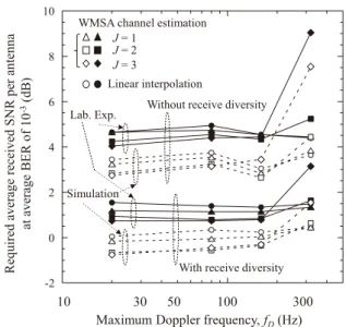
Fig. 5 Required average received SINR at the average BER of10−3using SIR-based TPC and turbo code[7].
satisfies the target average bit error rate (BER) of 10−3 as a function of the maximum Doppler frequency, fD, when using SIR-based TPC and turbo code[7]. These results are based on laboratory experiments using a multipath-fading simulator. In the equipment used in the experiment, we em- ployed a time division multiplexing pilot symbol structure.
The channel gain for the data symbols of each slot was es- timated using the coherently combined estimated channel gains at pilot symbol locations across multiple slots, which we denote as weighted multi-slot averaging (WMSA) chan- nel estimation in the figure [7]. Parameter J in the figure denotes the number of slots on one side which are used for WMSA channel estimation with the target slot as the center.
The weighting factors are optimized from the BER in a mul- tipath Rayleigh fading channel[7]. We used a turbo code with the coding rate of 1/3 and the constraint length of 4.
We assumedL=2paths with equal average received signal power, each of which suffered from independent Rayleigh fading. We used two-antenna receive diversity. From the figure, according to the increase in the fading maximum Doppler frequency caused by the fast user mobility, the abil- ity of the TPC to track the fast fading variation is degraded which brings about an increase in the required received SINR for satisfying the target average BER. In contrast, the channel interleaving effect over one radio frame duration is improved in a faster fading channel. This leads to an increase in the turbo coding gain. Hence, SIR-based TPC and turbo cod-
ing associated with bit interleaving across one radio frame duration works complementarily in low-to-high mobility en- vironments up to approximately 300 km/h. We also see that the WMSA PSA channel estimation withJ= 2 achieves a low required average received SINR for low-to-high maximum Doppler frequencies up to approximately 300 Hz.
3. HSDPA and HSUPA
3.1 HSDPA
(1) Background and HSDPA radio interface[10]
When W-CDMA commercial service was launched in 2001, the amount of data traffic had been increasing remarkably due to the spread of mobile Internet. The resource assign- ment method using a dedicated channel in W-CDMA was effective in multiplexing low-rate physical channels carrying voice traffic with low latency through the averaging effect of multiuser interference with an independent distribution. The resource utilization efficiency of a dedicated channel was in general low because it took time for physical channel setup.
In addition, it was inappropriate to increase the peak data rate for data service. Moreover, resource assignment includ- ing the spreading code and transmit power was conducted at a radio network controller (RNC), not at a BS called a Node B in W-CDMA. Accordingly, transmission delay including the round trip delay of automatic repeat request (ARQ) in a radio link control (RLC) sublayer in Layer 2 (L2) became long in W-CDMA.
Hence, in HSDPA, a shared channel called the High- Speed Downlink Shared Channel (HS-DSCH) was specified to carry high-speed user data efficiently. HSDPA was the enhanced transport channel of the downlink shared channel for W-CDMA. Major radio parameters including the chip rate, transmission bandwidth, and radio frame length were identical to those in W-CDMA. The same radio parameters enabled the coexistence of HSDPA and W-CDMA in the same frequency spectrum. However, a resource unit carry- ing user data was assigned every 2 ms and was referred to as the transmission time interval (TTI). The TTI of HSDPA cor- responded to three slots in W-CDMA. The physical channel that multiplexes the HS-DSCH was called the HS-Physical Downlink Shared Channel (PDSCH). The only spreading factor supported in the HS-PDSCH was 16. The number of multiplexed code channels was 5, 10, and 15 at maxi- mum. The modulation schemes used were QPSK, 16QAM, and 64QAM (64QAM was added in the Rel. 7 specifica- tion). The mother coding rate of the turbo code was 1/3 and coding rates higher than 1/3 were generated by punc- turing the parity bits. Soft handover was not supported for the HS-DSCH in HSDPA. In the HSDPA radio interface, two control channels were specified: the HS-Shared Con- trol Channel (SCCH) in the downlink and the HS-Dedicated Control Channel (DPCCH) in the uplink. The HS-SCCH carried the modulation scheme, channelization code, and UE-ID in the first part, and the redundancy and constella-
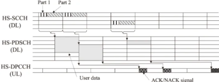
Fig. 6 Example of physical channel assignment in HSDPA.
tion version, transport block (TB) size information, hybrid ARQ (HARQ) process information, and new data indicator in the second part. The HS-DPCCH carried the acknowledge- ment (ACK)/negative-acknowledgement (NACK) for HARQ of HS-DSCH and channel quality indicator (CQI) which was represented as an appropriate set of modulation and coding schemes (MCSs) satisfying the block error rate (BLER) of less than 10%. Using MCSs as a CQI enables the possible application of an advanced receiver in the future.
(2) Key HSDPA radio access technologies[3],[4],[10]
In HSDPA, radio resources were assigned to the best user by using channel-dependent scheduling based on the reported CQI from the set of UEs and on the quality of service (QoS) requirement for the offered traffic. Adaptive rate control using adaptive modulation and coding (AMC) was used ac- cording to the UE channel conditions. The user data rate was controlled by the modulation scheme, coding rate of the turbo code, and the number of multiplexed code channels with the fixed spreading factor of 16. A six-channel stop and wait protocol was used for ARQ in the HS-DSCH. Hybrid ARQ (HARQ) associated with soft combining was another effective technique that reduced block errors. In HSDPA, fast HARQ based on incremental redundancy was adopted with a short round trip delay of 6 TTIs in the medium ac- cess control (MAC) layer at a Node B. Figure 6 shows an example of the physical channel assignment in HSDPA. The UE first decodes the scheduling grant and information in the HS-SCCH, which is necessary to demodulate and decode the HS-PDSCH. Then, the UE demodulates and decodes the HS-DSCH and detects whether or not block error occurs based on cyclic redundancy check (CRC) calculation. The UE feeds back ACK/NACK information to a Node B using the HS-DPCCH in the uplink.
In packet radio access using a shared channel, the in- crease in the peak data rate directly lead to an increase in the system capacity or cell throughput that a Node B offered successfully to UEs within a cell. The achievable peak data rate was 14.4 Mbps for HSDPA based on the Rel. 5 speci- fication assuming one-antenna transmission and 16QAM. It was enhanced to 168.8 Mbps based on Rel. 10 HSDPA us- ing 64QAM, 2-by-2 multiple-input multiple-output (MIMO) multiplexing, and 4 carriers. Smooth enhancement was achieved by an increase in the modulation order, the num- ber of available antennas, and extending the transmission bandwidth.
3.2 HSUPA[3],[10]
A new transport channel called the Enhanced Dedicated Channel (E-DCH) was specified for carrying user data in HSUPA. The E-DCH was multiplexed into the Enhanced Dedicated Physical Data Channel (E-DPDCH). The En- hanced Dedicated Physical Control Channel (E-DPCCH) carried low layer control signals that associate with the E- DPDCH. In the uplink, wide area coverage was required with higher priority compared to the increase in the link capac- ity. Hence, the modulation scheme was QPSK in the Rel.
6 specification. The TTI length of 2 ms was added to that of 10 ms. TPC and soft handover were used as well as the DPCH of W-CDMA. Hybrid ARQ with soft combining was applied. The achievable peak data rate was 5.67 Mbps with QPSK in the Rel. 6 specification and it was enhanced to 22.5 Mbps using 16QAM and a 10-MHz bandwidth in the Rel. 10 specification.
4. LTE
4.1 System Requirements[11],[12]
Radio access networks (RANs) that have high affinity to all Internet protocol (IP) based core networks should achieve ef- ficient multiplexing of data traffic including video messages and download. In LTE, only packet based MA schemes em- ploying a shared channel are specified along with the voice over IP (VoIP) capability in the packet-switching domain.
Multiple scalable transmission bandwidths with a maximum of 20 MHz are specified so that LTE is deployed for the existing frequency spectra. Low latency including a short transmission delay in a RAN such as less than 5 ms one way is required. Requirements for the peak data rate are 100 Mbps and 50 Mbps in the downlink and uplink, respec- tively. Higher cell throughput and cell-edge user through- put requirements are specified compared to those for Rel.
5 HSDPA and Rel. 6 HSUPA in the downlink and uplink, respectively.
4.2 MA Schemes[12]–[14]
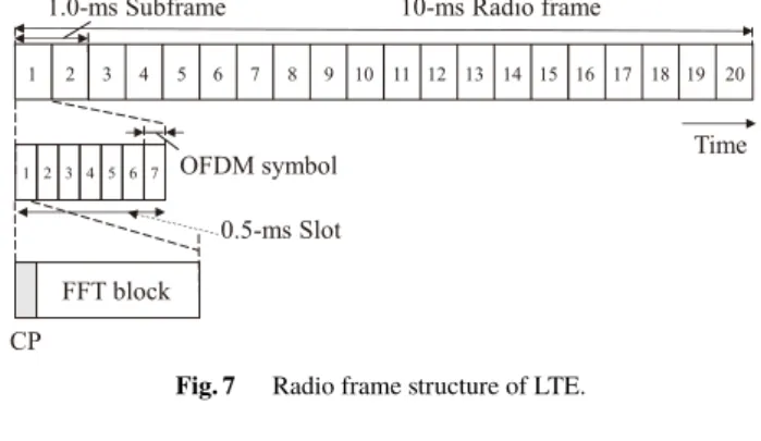
Figure 7 shows the radio frame structure of LTE. One 10- ms long radio frame comprises ten 1-ms subframes. The subframe represents a resource assignment unit that carries a TB. Moreover, one subframe comprises two slots and the slot length is 0.5 ms. The subcarrier spacing is 15 kHz in OFDM- based signaling, which is decided from a tradeoff relationship between improving the subframe efficiency considering the overhead due to cyclic prefix (CP) insertion and mitigating the influence of phase noise due to the difference in frequency accuracy between an eNode B and a UE (note that a BS is called an eNode B in LTE). The effective symbol duration or FFT block length is 66.67µs for the normal CP length of 4.7µs. In addition to the normal CP, an extended CP of 16.67 ms is adopted for, e.g., the Multimedia Broadcast
Fig. 7 Radio frame structure of LTE.
Fig. 8 Trends in MA schemes from the viewpoint of interference coordi- nation.
Multicast Service (MBMS) using a single frequency network (SFN). For instance, the number of subcarriers is 300 and 600 for the system bandwidth of 5 and 10 MHz, respectively.
A resource unit with 12 subcarriers in the frequency domain and a slot length in the time domain is called a resource block (RB).
Figure 8 shows trends in the MA schemes for the respec- tive generation systems from the viewpoint of interference coordination (IC) among multiplexed physical channels. In the W-CDMA downlink, intra-cell orthogonal multiplexing of physical channels was achieved only within the same prop- agation path. The full intra-cell orthogonal multiplexing of physical channels is adopted in both the downlink and up- link for LTE. The intra-cell orthogonal multiplexing con- tributes to decreasing the required received SINR to satisfy the target BLER. Inter-cell interference randomization us- ing a cell-specific scrambling code is the baseline scheme in LTE. However, to mitigate co-channel interference from the neighboring cells at the cell edge, fractional frequency reuse (FR) is introduced [12]. In fractional FR, three-cell FR is employed at the cell edge while one-cell FR is used in the cell center area. Moreover, inter-cell IC in the frequency do- main is specified to reduce the strong inter-cell interference [12]. In LTE-Advanced, inter-cell IC in the time domain is introduced in heterogeneous networks by muting macrocell transmissions, which decrease the interference suffered by a small cell[12]. Coordinated multi-point (CoMP) transmis- sion and reception are also specified to improve the achiev- able throughput at the cell edge for LTE-Advanced.
In standardization of the LTE radio interface, high com- monality of radio parameters including the frame structure is requested between FDD and TDD modes. Hence, the same frame structure and MA schemes are specified for both FDD and TDD modes. In the downlink, OFDMA is adopted
Fig. 9 Transmitter structure in OFDMA downlink.
because of its inherent immunity to multipath interference (MPI) and its support of different transmission bandwidth arrangements from 1.4 MHz to the maximum of 20 MHz.
The MPI is mitigated using a low symbol rate per subcarrier and a cyclic prefix, which is appended to each fast Fourier transform (FFT) block. Figure 9 shows the transmitter struc- ture in the OFDMA downlink. Similar to W-CDMA, a turbo code with the mother coding rate of 1/3 is adopted as the channel coding scheme for data channels in LTE. An infor- mation data sequence called the TB is segmented and the CRC is attached. The bit sequences are turbo-encoded and rate matching is performed. After the coded bits are mapped into a modulation symbol, channel interleaving is performed.
The modulated symbols are serial-to-parallel-converted and multiplexed with control channels. The parallel symbol se- quences are converted into OFDM signals by an inverse FFT (IFFT) followed by appending a CP and windowing.
In the uplink, SC-FDMA is adopted for its prioritiza- tion of wide area coverage provisioning due to a reduction in the transmission back-off in the transmitter power ampli- fier. Discrete Fourier transform (DFT)-spread orthogonal frequency division multiplexing (OFDM) is adopted that generates SC-FDMA signals in the frequency domain (note that DFT-spread OFDM is also referred to as DFT-precoded OFDM)[15]. Figure 10 shows the transmitter structure for DFT-spread OFDM. By using frequency domain processing, the same radio parameters including the subcarrier spac- ing, FFT block size, and subframe length are designed for both OFDMA and DFT-spread OFDM. In the DFT-spread OFDM, inter-FFT block interference is mitigated by the use of a CP similar to that in downlink OFDMA. In addition, intra-FFT block interference is mitigated by using a channel equalizer. In LTE, a frequency domain equalizer (FDE) is used[15],[16]. In the FDE, the equalized weight based on, e.g., the minimum mean-square error (MMSE) criterion is multiplied to the received subcarrier signal. In contrast, a time domain equalizer requires convolution operation of the received signal and the equalizer weights. Consequently, the FDE provides lower computational complexity compared to the time domain equalizer and achieves a practical imple- mentation level for the UE.
We note that some promising technologies including in- terleave division multiple access (IDMA)[17]and OFDM/
Isotropic Orthogonal Transform Algorithm (IOTA) [18]
were proposed as a Study Item (SI) for LTE standardiza- tion. In the end, however, CP based OFDMA and DFT- spread OFDM were adopted. Both OFDMA and DFT-spread OFDM need a simple one-tap equalizer or coherent detector per subcarrier in the time and frequency domains. This re-
Fig. 10 Transmitter structure for DFT-spread OFDM.
Fig. 11 Transmission scheme for physical channel multiplexing in LTE downlink.
sult suggests that the implementation cost particularly for a UE is another important requirement.
4.3 Physical Channel Overview
In LTE, physical channels and signals based on OFDMA and those based on SC-FDMA are specified in the LTE Rel.
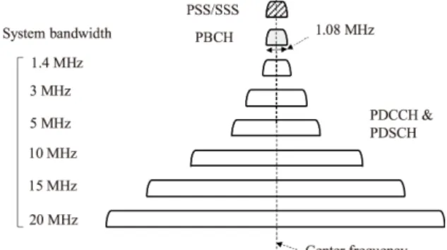
8 specifications. Figure 11 shows the transmission scheme for the physical channel multiplexing in the LTE downlink.
In the LTE downlink, the Primary Synchronization Signal (PSS), Secondary Synchronization Signal (SSS), and Phys- ical Broadcast Channel (PBCH) are specified for the initial acquisition procedure. Both the PSS and SSS are transmitted with a 945-kHz bandwidth from the central part of the en- tire transmission band regardless of the system bandwidth.
In the LTE radio interface, 504 Physical cell IDs (PCIDs) are specified. The 504 PCIDs are divided into 168 PCID groups and 1 PCID group contains 3 PCIDs. The three PSS sequences correspond to three PCIDs within the same PCID group. When one eNode B has a three-cell configuration, different PSS sequences are assigned to the three cells within that eNode B. The SSS sequences indicate 168 PCID groups.
The PBCH is transmitted with a 1.08-MHz bandwidth from the central part of the entire transmission bandwidth and the TTI length of 40 ms. The PBCH carries the system informa- tion that is necessary for a UE to access the system. A part of the broadcast information including the Master Information Block (MIB) is also transmitted in the PBCH.
The Physical Control Format Indicator Channel (PC- FICH) indicates the number of OFDM symbols that is dy- namically reserved for control information at each subframe.
The Physical Downlink Control Channel (PDCCH) is mul-
Fig. 12 Contention based random access procedure in LTE uplink.
tiplexed into three OFDM symbols at maximum for each subframe across multiple RBs. The PDCCH carries Layer 1 (L1)/L2 control signals including the RB allocation infor- mation. The Physical HARQ Indicator Channel (PHICH) indicates whether or not the uplink packet is decoded cor- rectly without error. The Physical Downlink Shared Chan- nel (PDSCH) carries user data and high-layer control sig- nals. By adopting OFDMA, the granularity in the fre- quency domain becomes much finer compared to that for W-CDMA/HSDPA with a 5-MHz transmission bandwidth.
Hence, frequency domain channel-dependent scheduling is used for the PDSCH to achieve a larger multiuser diversity effect. AMC with QPSK, 16QAM, 64QAM, 256QAM (op- tional use), and HARQ based on incremental redundancy are used for the PDSCH as well.
In the uplink, the received timings of simultaneously ac- cessing UEs are asynchronous due to the different propaga- tion time delays from a cell site. When the received time de- lay exceeds the CP length, orthogonality among users in the same subframe duration is destroyed. Hence, transmission timing control (TTC) is used in the uplink so that the received timings of the simultaneously accessing users are aligned within the CP duration for the Physical Uplink Shared Chan- nel (PUSCH). Figure 12 shows a contention based random access procedure in the LTE uplink. A Zadoff-Chu sequence [19], which belongs to the family of constant amplitude zero autocorrelation (CAZAC) codes, is used as a random access preamble sequence. A UE transmits a random access pream- ble in the Physical Random Access Channel (PRACH) using power ramping after decoding the system information in the PBCH. The eNode B transmits a random access response that contains a timing alignment command and scheduling resources of the first transmission in the PUSCH included in the uplink for the target UE to use. Preamble collision occurs at approximately 1% of the time because a few UEs transmit the same preamble using the same frequency and time resources[20]. Hence, the UE transmits the identity to the eNode B using the allocated resources. The eNode B transmits a contention-resolution message to resolve the col- lisions. The above-mentioned process achieves contention- free orthogonal multiplexing among simultaneously access- ing data channels in the uplink. The Physical Uplink Control Channel (PUCCH) is specified to carry control signals when
Fig. 13 Operation of closed-loop MIMO spatial multiplexing.
there are no uplink data in the subframe. Since the PUCCH has a narrowband with 1 RB, intra-subframe frequency hop- ping is used to improve the BLER via frequency diversity.
The PUSCH carries user data, L1/L2 control signals when there are uplink data, and high-layer control signals. Fre- quency domain channel-dependent scheduling, TPC, AMC, and HARQ are used for the PUSCH.
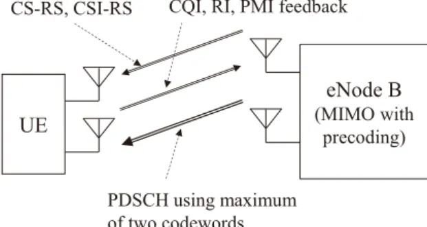
4.4 Key Techniques Satisfying System Requirements The low transmission delay of 5 ms is achieved by a 1-ms subframe that corresponds to the TTI and the round trip delay becomes 8 TTIs. The adopted modulation schemes are QPSK, 16QAM, and 64QAM, although 64QAM is used optionally in the uplink. In a later specification, 256QAM was adopted as an option in the downlink. In the downlink, maximum 4-by-4 MIMO channel transmission is adopted including spatial multiplexing and transmit /receive diver- sity. In the LTE downlink, both open-loop and closed-loop MIMO spatial multiplexing schemes are adopted. Figure 13 shows the operation of closed-loop MIMO spatial multiplex- ing. In the LTE specifications, codebook based precoding is adopted to decrease feedback signals. A UE measures the channel state information (CSI) by using cell-specific refer- ence signals (CS-RSs) for up to four antennas or CSI-RSs.
The UE decides the number of streams and precoding ma- trix that provide the maximum throughput. The UE feeds back the CQI, precoding matrix indicator (PMI), and rank indicator (RI) signals to an eNode B. The eNode B transmits the PDSCH with the selected MCS and MIMO spatial mul- tiplexing schemes. One-antenna transmission is adopted in the LTE uplink.
The requirements for cell throughput, cell-edge user throughput, and frequency efficiency in the LTE downlink are achieved by the application of the intra-cell orthogo- nal MA scheme using OFDMA, 64QAM, frequency do- main scheduling, and the maximum 4-by-4 MIMO multi- plexing. Similarly, these requirements in the LTE uplink are achieved by the application of DFT-spread OFDM, 16QAM, frequency-domain scheduling, and receive diversity with the maximum of 4 antennas. The peak data rate of 100 Mbps is achieved employing 64QAM and 2-by-2 MIMO multiplex- ing with a 20-MHz transmission bandwidth in the downlink.
Moreover, the peak data rate of greater than 300 Mbps is
achieved using 4-by-4 MIMO multiplexing associated with the aforementioned other conditions on downlink. In the uplink, the peak data rate of 50 Mbps is achieved through a 20-MHz bandwidth using 16QAM and 2-antenna receive di- versity. Moreover, the peak data rate of 75 Mbps is achieved by using 64QAM together with the same other conditions.
5. LTE-Advanced
5.1 System Requirements[20]–[22]
In the ITU-R, the system requirements for IMT-Advanced were specified including the achievable peak data rates of 100 Mbps and 1 Gbps for high mobility and low mobility environments, respectively. The system requirements for LTE-Advanced were specified so that they satisfy the IMT- Advanced requirements. More specifically, the requirement for the peak data rate is 1 Gbps and 500 Mbps in the down- link and uplink, respectively. The requirement for a higher cell throughput or system capacity and that for the cell-edge user throughput were specified compared to those of LTE.
The higher requirements are flexibly achieved by increasing the number of available antennas for MIMO spatial divi- sion multiplexing (SDM) and the system bandwidth up to 100 MHz using CA based on the same MA schemes as those for LTE. The approach to increase the frequency and/or spa- tial resources is very beneficial to improving the achievable performance smoothly and flexibly based on the same MA schemes.
5.2 Carrier Aggregation (CA)[21],[22]
To maintain backward compatibility with the LTE radio in- terface, it is necessary to achieve a higher peak data rate, cell throughput, cell-edge user throughput, and more efficient us- age of radio resources that are distributed across the entire transmission bandwidth compared to those for Rel. 8 LTE.
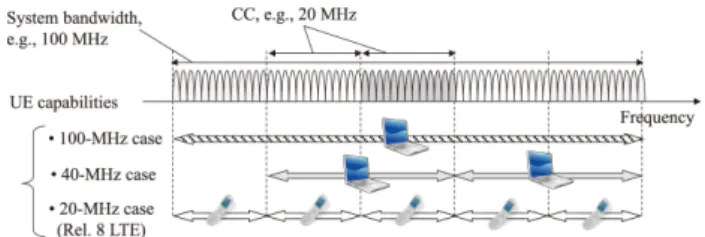
Hence, the CA concept is adopted in which the total transmis- sion bandwidth for each link comprises contiguous or non- contiguous component carriers (CCs). Figure 14 shows the CA operation for LTE-Advanced. The transmission band- width of each CC corresponds to the maximum bandwidth of the LTE radio interface or 20 MHz. Hence, a cell site for LTE-Advanced can establish a radio link with a legacy LTE UE and vice versa. Five CCs are specified to achieve the maximum transmission bandwidth of 100 MHz in the Rel. 10 specifications. In particular, CA with non-contiguous CCs enables flexible usage of frequency resources with different frequency spectra. Within a CC, the same MA schemes as those in LTE are used. In the uplink,N-times DFT-spread OFDM is used to generate a wider transmission bandwidth than 20 MHz across multiple CCs. A clustered transmission scheme is adopted in addition to the localized transmission mode to achieve a more flexible resource assignment in the frequency domain.
Fig. 14 CA operation for LTE-Advanced.
5.3 MIMO Channel Techniques[21],[22]
In order to satisfy the higher system requirements for LTE- Advanced, MIMO channel techniques have evolved beyond those in LTE. The single-user (SU) and multiuser (MU)- MIMO multiplexing schemes with the maximum of 8-by-8 and 4-by-4 antenna configurations are adopted in the down- link and uplink, respectively. The requirements for the peak data rate of 1 Gbps and 500 Mbps are achieved by wider transmission bandwidths up to 100 MHz and by the maxi- mum of 8-by-8 or 4-by-4 MIMO multiplexing schemes in the downlink and uplink, respectively. Moreover, the peak data rate of 3 Gbps will be achieved by using 64QAM and 8-by-8 MIMO multiplexing with 100 MHz transmission bandwidth.
The peak frequency efficiencies of 16.3 and 8.4 bits/s/Hz are achieved by 4-by-2 and 2-by-4 SU-MIMO spatial mul- tiplexing in the downlink and uplink, respectively. More- over, higher system capacities compared to those for LTE are achieved mainly by MU-MIMO in the downlink with which an eNode B with four antennas or more can accom- modate multiple UEs with two antennas simultaneously us- ing SDM. In the uplink, SU-MIMO improves the capacity as well as MU-MIMO. The improvement in the cell-edge user throughput is achieved mainly by CoMP transmission in the downlink and the application of codebook based transmit diversity in the uplink. To support multi-antenna techniques with more than four antennas, new RSs are specified includ- ing a CSI-RS and a UE-specific demodulation RS (DM-RS) that suppress an increase in the RS overhead to a low level.
To enable efficient transmission of user traffic, control channels such as the physical downlink control channel (PD- CCH) are specified. The PDCCH carries downlink control information (DCI) that includes the downlink resource as- signment, uplink resource grant, MCS information, and/or other control information for a UE. The PDCCH is multi- plexed by time division multiplexing at up to three or four OFDM symbols at the beginning of each subframe. How- ever, the PDCCH transmits a limited number of DCI mes- sages, which is a bottleneck for the cross-carrier scheduling among multiple CCs in CA, MU-MIMO, and CoMP. Hence, the enhanced PDCCH (EPDCCH) is specified in the Re1.
11 specifications[23]. In the EPDCCH, frequency division multiplexing is adopted to achieve increased control channel capacity and to support frequency domain inter-cell inter- ference coordination (ICIC), frequency domain scheduling, and beamforming. Moreover, advanced UE receivers in-
cluding interference rejection combining (IRC) and low cost MTC are investigated for the Rel. 11 specifications. Full dimension (FD)-MIMO is investigated that utilizes a two- dimensional antenna array[24]. FD-MIMO forms narrow beams to achieve MU-MIMO in the azimuth and elevation domains. The related RSs are specified in the Rel. 13 speci- fications.
5.4 Heterogeneous Networks[21],[22]
As mentioned earlier, the system capacity has been increased by BS densification using local cells or small cells. In the conventional local cell deployment, a local-area cell site is a stand-alone system that operates independently from a macrocell. A local cell node has the same functions as those of a macrocell node such as transmission of the cell-specific RS, and system- and cell-specific control information. A UE can connect a radio link with either a macrocell or local cell.
Heterogeneous networks (HetNets) in which a macro- cell is overlaid onto small cells or local cells including micro and picocells have recently drawn attention[25],[26]. A macrocell guarantees wide area coverage mainly focusing on the control plane and on high-mobility UEs. Hence, relatively low frequency spectra including the 2-GHz band are anticipated to be deployed for a macrocell. Meanwhile, the small cells mainly accommodate UEs that demand high- speed data services and are under low mobility conditions.
It is anticipated that a high frequency spectrum including the millimeter wave band will be used since a broad bandwidth is to be accommodated in such a high frequency spectrum.
In[27], several typical deployment scenarios for Het- Nets were specified. In the scenario using the same fre- quency spectrum for a macrocell and outdoor small cell, the coverage area is extended compared to the cell configuration with only a macrocell. Dynamic interference coordination in the time domain using an almost-blank subframe is specified to avoid co-channel interference from a macrocell to a small cell. The deployment scenarios using separate frequency spectra between a macrocell and an outdoor or indoor small cell are specified as scenarios #2a and #2b, respectively.
The scenarios employing separate frequency spectra provide more flexible deployment of small cells in an area with high traffic demand compared to those using the same frequency spectrum because they do not suffer from mutual co-channel interference.
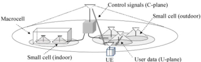
Assuming HetNets, the phantom cell concept and soft cell concept associated with a lean carrier were proposed in [28]and[29], respectively. Figure 15 shows the operating principle of the phantom or soft cell concepts. In these con- cepts, a small cell operates in cooperation with a macrocell.
A macrocell guarantees wide area coverage mainly focus- ing on control signals in the control plane including system information, radio resource control (RRC) information, and low-rate user data for high-mobility users. The small cells mainly accommodate UEs that demand high-speed data ser- vices and are under low mobility conditions. The overhead of the RS and control signals is decreased for a small cell
Fig. 15 Phantom cell or soft cell concept in heterogeneous networks.
Fig. 16 Relay concept in LTE-advanced.
achieving a lean carrier that decreases the amount of inter- ference imparted to the surrounding cells and operational cost.
5.5 Relays[21],[22],[30]
The LTE and LTE-Advanced radio interfaces achieve high user throughput when the received SINR is high. However, when the received signal power level becomes low such as indoors and at the cell edge of a macrocell, the achievable throughput is reduced. An RF repeater that boosts the signal power level has been deployed in the existing cellular net- works to improve the coverage area. In the Rel. 10 specifica- tions, relays were specified based on the LTE radio interface to extend the coverage area at low cost.
Figure 16 shows the relay concept for LTE-Advanced [21]. The radio link between a donor eNode B and relay node is referred to as a backhaul link. Relaying is regarded as a wireless backhaul that is used to configure independent cells. The radio link between the relay node and a UE is referred to as an access link. In the LTE relay, the same LTE radio interface as that for the access link is used for the backhaul link. The radio protocols for the access link, i.e., between the relay node and UE, for both the control and user planes are terminated at the relay node. Hence, a relay node appears similar to an eNode B from the UE viewpoint. From a core network viewpoint, a relay node appears similar to a sector in the donor eNode B.
The relay schemes specified are categorized into inband and outband relays. In an outband relay, different frequencies are used between the access link and backhaul link at the cost of additional use of the frequency spectrum. In this case, high level isolation is necessary between the different frequencies. The inband relay employs the same frequency
for both the access link and backhaul link. In this case, there is no interference between the backhaul link and access link because these links are separated in the time domain. In contrast, the transmission delay in the inband relay is longer compared to that in the outband relay.
The Multicast Broadcast Single Frequency Network (MBSFN) subframe for the MBMS is used for data trans- mission in a backhaul link from a donor eNodeB to a relay node. Moreover, a new control channel called the Relay PDCCH (R-PDCCH) is specified as a backhaul link that is multiplexed after the PDCCH.
5.6 CoMP[21],[31],[32]
When using soft handover in the downlink adopted for W-CDMA, multiple physical channels with different cell- specific scrambling codes are transmitted from multiple cell sites, i.e., eNode Bs. However, due to the mutual interference among the simultaneously transmitted channels, the macro diversity gain is limited in the downlink. Moreover, soft han- dover requires an increase in the implementation complexity of a higher layer node such as RNC and that of a UE. Hence, soft handover is not adopted due to the small macro diver- sity gain and high implementation complexity and signaling overhead in LTE. The improvement in the cell-edge user throughput is still one of the most important system require- ments for LTE with one-cell frequency reuse as a baseline.
To improve the cell-edge user throughput, the usage of power resources of multiple cell sites is the most effective method.
Hence, CoMP transmission and reception are investigated and the related signaling is specified in the Rel. 11 radio interface.
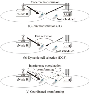
Figure 17 shows CoMP transmission schemes in the downlink where coordinated cells referred to as a CoMP set comprise an eNode B and a remote radio head (RRH). A centralized controller is equipped in the eNode B. The RRH comprises an RF transceiver only and it is connected to the eNode B through a fast X2 interface.
Two transmission schemes are mainly considered: joint processing (JP), and coordinated scheduling and beamform- ing (CS/CB). In JP, the network provides user data to the target UE from multiple cells. Hence, radio resources of the multiple cell sites are used for the target UE. JP is further categorized into joint transmission (JT) and dynamic cell selection (DCS). Figures 17(a) and 17(b) show transmission schemes for JT and DCS, respectively. In JT, the same RB of the PDSCH is transmitted from multiple cells associated in a CoMP set, i.e., from a non-serving cell(s) as well as the serving cell as shown in Fig. 17(a). JT is achieved by code- book based precoding to reduce feedback signal overhead.
Since the transmission power resources of multiple cell sites can be used through coherent transmissions, the cell-edge user throughput can be improved significantly. In DCS, a RB of the PDSCH associated with a UE-specific DM-RS is transmitted from one cell among a CoMP set, and the cell transmitting the PDSCH with the minimum path loss is dy- namically selected through fast scheduling at the centralized
Fig. 17 CoMP transmission schemes in downlink.
controller in the eNode B as shown in Fig. 17(b). Then, the other cells in a CoMP set are muted, i.e., they do not transmit the RB, so that the cell-edge UE does not receive other-cell interference.
Figure 17(c) shows a transmission scheme for CS/CB.
Unlike the aforementioned DCS, a RB of the PDSCH is trans- mitted only from the serving cell together with the PDCCH.
Hence, the RB is assigned to the target UE by scheduling at the serving cell for coordinated scheduling and beamform- ing. However, coordinated scheduling and beamforming are performed jointly with other cells in a CoMP set. In this case, transmit beamforming weights for each UE are gener- ated to reduce the unnecessary interference to other UEs that are scheduled within a CoMP set. Therefore, cell-edge user throughput can be improved due to the decreased other-cell interference.
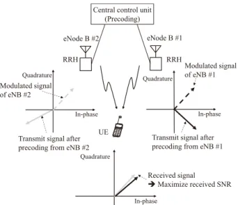
Figure 18 shows the operating principle of CoMP trans- mission in the downlink. CoMP transmission in the down- link is similar to soft handover in that the data channels transmitted from multiple cell sites are combined at a UE.
However, unlike in soft handover, multiple data channels carrying the same user data are combined without suffering from mutual interference. This is because the same signals are transmitted after being multiplied by the best respective precoding matrix so that the received SINR of the combined signal at a UE is maximized. Note that DPCHs suffer from mutual interference in soft handover due to the different cell- specific scrambling codes in the W-CDMA downlink. The influence of channel estimation error is large in W-CDMA since accurate channel estimation is necessary to combine coherently the data channels from multiple cells within the active set. In contrast, the influence of the channel estimation
Fig. 18 Operating principle of CoMP transmission in downlink.
error is low for CoMP transmission in the downlink. This is because the estimated channel response associated with each antenna port is used only to select the best precoding vector from the limited number of codebooks.
In CoMP reception in the uplink, the PUSCH is re- ceived by multiple cells. In this case, IRC, MMSE, or the zero forcing (ZF) algorithm is used to combine the received PUSCHs at the multiple cell sites.
6. Radio Interfaces for Machine-Type Communications (MTC)
LTE and LTE-Advanced achieve broadband data services with various QoS requirements for a set of UEs in cellular networks. The demands to apply wireless communications to smart power meters, remote control of machines, security cameras, data collection from numerous sensors, cars, and home electronics are increasing. The UE category with a low cost referred to as category 0 was specified in the Rel. 12 specification, which achieves the maximum data rate of 1 Mbps without receive diversity for half duplex FDD [24],[33].
Two types of UE categories are specified that achieve low cost MTC UEs and further extend the coverage area in the Rel. 13 specifications. The first UE category is called cat- egory M1. In this category, the transmission and reception bandwidths are confined to 1.08 MHz, which corresponds to 6 RBs. A UE based on category M1 can receive the PSS/SSS and BCH of the Rel. 8 LTE radio interface because these are transmitted with a 6-RB bandwidth. However, the UE cannot receive the PDCCH that is necessary to demodulate and decode the PUSCH containing the System Information Block (SIB). This is because the PDCCH is transmitted with a system bandwidth that is wider than 6 RBs. Hence, a new PDCCH with a 6-RB bandwidth called the MTC-PDCCH (M-PDCCH) is specified so that a category M1 UE can de- code the SIB.
Fig. 19 Multiplexing scheme for the downlink NB-IoT physical channels in downlink.
The second category is called the Narrowband (NB)- IoT category [34]. In this category, the transmission and reception bandwidth is 180 kHz (= 1 RB). Hence, the NB- IoT category achieves lower complexity, longer UE battery life, and wider coverage-area provisioning compared to the M1 category although the offered data rate and frequency efficiency are decreased. Because the transmission band- width in both links is only 180 kHz, a NB-IoT category UE cannot demodulate and decode the PSS/SSS and PBCH based on the LTE radio interface. Hence, new NB-IoT phys- ical channels are specified in the Rel. 13 specifications. In the downlink, NPSS, NSSS, NPBCH, NRS, NPDCCH, and NPDSCH are specified where the “N” denotes narrowband.
In the uplink, the NPRACH and NPUSCH are newly speci- fied. Figure 19 shows a multiplexing scheme for the NB-IoT physical channels in the downlink. As shown in the figure, NB-IoT physical channels and signals are multiplexed in the time domain primarily due to the 1-RB bandwidth.
The NPSS and NSSS are used to perform cell search that includes the processes of timing detections, time and fre- quency synchronization, and cell ID detection. The NPBCH carries the MIB, which is unchanged during the 640-ms TTI. The NPDCCH carries scheduling information for the NPDSCH and NPUSCH, acknowledgement information for the uplink HARQ, paging dedication, and random access re- sponse. A NRS is used for coherent detection of the NPBCH, NPDCCH, and NPDSCH. The NPDSCH carrying user data employs only QPSK data modulation and tail-biting convo- lutional code associated HARQ with only one redundancy version.
One NPRACH preamble comprises four symbol groups where each symbol group comprises one CP and five sym- bols. The NPRACH is used to establish a radio link, trans- mission of scheduling requests, and achieving uplink syn- chronization. The NPUSCH carrying user data (Format 1) employs a turbo code, while the NPUSCH carrying ac- knowledge signaling of HARQ for the NPDSCH (Format 2) employs a repetition code.
Three deployment options are specified for NB-IoT: de- ployment for a stand-alone carrier in any available spectrum that is wider than 180 kHz, that inside an LTE carrier, and that in the guard band in the LTE spectrum.
7. 5G Cellular Systems
7.1 System Requirements
The SI investigation for a new radio interface for 5G cellular systems has been initiated in the 3GPP. The SI aims at de- veloping a single technical frame work that addresses usage scenarios including enhanced mobile broadband (eMBB), massive MTC, and ultra-reliable low latency communica- tions (URLLC)[35],[36]. 5G radio access networks will provide broadband services with the user rate of a few giga- bits per second at maximum. The aggregated peak data rate of a shared channel will be higher than a few tens of gigabits per second. Moreover, it is desirable for the peak data rate to be enhanced to near 100 Gbps based on the same radio in- terface by increasing the number of available antennas in the spatial domain and transmission bandwidth in the frequency domain. Another important requirement is to support MTC traffic flows for IoT in which all kinds of devices includ- ing factory machines, automobiles, home electronics, and sensors are connected to the Internet. Remote control op- eration for massive IoT traffic flows is possible by using the wireless channel with low latency. In particular, extremely low latency such as 1 ms is necessary for the application to mission-critical data such as automobiles. Meanwhile, ex- tremely low power consumption is needed for sensor devices.
7.2 OFDM Based MA Schemes
The 5G radio access scheme must support a significantly wide range of user data rates from a few kilobits per second to a few tens of gigabits per second. Moreover, it should achieve latency shorter than 1 ms for the mission-critical MTC traffic flows. A new radio interface is necessary to sat- isfy such very low latency and low BLER requirements. It is not necessary that one MA scheme support the wide range of system requirements for the offered data rates, latency, and BLER. Hence, a unified frame structure concept was proposed that comprises multiple subbands having different radio parameter sets (or numerology) and MA schemes as shown in Fig. 20[37]. Type I indicates high-volume broad- band traffic for which orthogonal access with grant based scheduling and TTC are used. Type II means a system which operates without rigid timing synchronization among UEs. Type III indicates a MTC traffic which is carried based on grant-free access for decreasing signaling overhead and power consumption.
In the 3GPP specification referred to as the new radio (NR), the subframe duration is 1 ms and the reference sub- carrier spacing for defining the subframe duration is 15 kHz [38]. The number of subcarriers within a physical resource block (PRB) is 12[38]. For the system requirements, low latency, i.e., shorter transmission delay for URLLC, affects the radio parameters. This shorter transmission delay is achieved either by reducing the number of OFDM symbols
Fig. 20 Unified frame structure.
including the CP, i.e., FFT blocks, within a slot or by de- creasing the OFDM symbol duration. Both approaches are adopted in the 3GPP specifications [37]. The first one is to adopt a mini-slot that comprises OFDM symbols with a CP of less than 7. The second approach is to adopt a subcarrier spacing of 15 x 2nkHz, wherendenotes a non- negative integer. Hence, it is necessary to accommodate multiple subbands with different subcarrier spacings, i.e., OFDM symbol duration within a system bandwidth. In this case, the orthogonality between the different subbands is no longer maintained. In LTE, an OFDM rectangular waveform without a pulse-shaping filter is adopted[37]. Hence, due to the high out-of-band emission (OOBE) level, 10% of the as- signed bandwidth is reserved as a guard band so that the side lobe signal is attenuated to a sufficiently low level to satisfy the spectrum mask. These reasons as well as a relaxed time synchronization requirement motivate the use of the OFDM waveform with a pulse-shaping filter. So far, various types of filtered-OFDM schemes have been proposed to achieve more efficient and flexible resource utilization compared to the OFDM waveform in LTE. Subcarrier-level pulse-shaping filtering is used in a filter-bank multicarrier (FBMC)[39]and subband (or RB) level filtering is applied to universal filtered (UF)-OFDM[40]. There is a tradeoff relationship between the requirement on the attenuation level of the side lobes and the computational complexity.
In the 3GPP specifications, it was approved that differ- ent numerologies within the same new radio bandwidth be multiplexed in the TDM and/or FDM manner for both the downlink and uplink[38]. Moreover, an OFDM waveform with a CP is adopted for both single-stream and multi-stream, i.e., MIMO channel transmission, transmissions[38]. The DFT-spread OFDM waveform is used complementarily to the OFDM waveform with a CP in the eMBB uplink[38].
7.3 Non-Orthogonal MA Schemes
As mentioned earlier, a one-tap equalizer per subcarrier is employed as a baseline receiver for LTE and LTE-Advanced.
Assuming an interference canceller such as the turbo soft in- terference canceller (SIC), non-orthogonal MA schemes are applicable for further improving the system capacity. Non- orthogonal MA schemes employing superposition coding [41], [42] and IDMA [17] were proposed and their per-
formance improvements in terms of the system capacity were reported. Moreover, non-orthogonal multiplexing or high-density packing of data symbols on resource elements, which is referred to as Faster-than-Nyquist (FTN), was pro- posed and its throughput improvements were investigated [43], [44]. It is considered that non-orthogonal MA and multiplexing schemes are effective in improving the system capacity for a small cell with a high offered traffic load.
In the uplink, non-orthogonal MA schemes were pro- posed that do not use grant-based resource assignment and tight transmission timing control to achieve a very short la- tency. A CDMA scheme using a low density signature (LDS) called LDS-CDMA was proposed for multiplexing massive physical channels with a low data rate[45]. Moreover, space code multiple access (SCMA) achieves direct mapping of coded bits to multi-dimensional codewords that corresponds to the symbol mapping and spreading with LDS[46]. Both schemes employ a message-passing algorithm (MPA) with low computational complexity at a receiver. In the 3GPP, MA schemes with low cross-correlation codes including a LDS and Zadoff-Chu sequence[19]were proposed[38].
From the application of non-orthogonal MA schemes, commonality with the existing orthogonal MA schemes is desirable in the same frequency spectrum. Moreover, a transparent channel in a higher layer must be multiplexed in the same way as that for orthogonal MA schemes. In 5G systems, the number of antennas will be increased to increase the beamforming gain and multiplexing gain[47].
In addition, the system bandwidth will become wider by tak- ing advantage of CA or spectrum aggregation. According to the increases in the number of antennas and the bandwidth, the number of the overhead signals including RSs for CSI measurement and feedback signals will be increased. TDD is more beneficial in reducing the number of the overhead signals compared to FDD by taking advantage of channel reciprocity.
8. Conclusion
In this paper, we presented the MA technologies for W- CDMA, HSDPA/HSUPA, LTE, and LTE-Advanced. We also described the requirements, envisioned challenges, and MA technology candidates for the future 5G systems.
In the 3GPP, the system requirements are specified first.
The best radio access techniques and numerology are speci- fied so that the system requirements are satisfied. This stan- dardization process leads to the development of an excellent radio interface. The conventional cellular systems suggest that major technical pillars are almost identical regardless of the radio access systems of the respective generation. Hence, according to the system requirements, the development of the key pillar technology is important. For the future 5G cel- lular systems, MTC, which will carry IoT traffic flows with very low latency and high quality will be another promising requirement in addition to the eMBB. Technologies that pro- vide the best performance considering the overhead of the RSs and control signals are desirable. Forward compatibil-
ity or smooth enhancement of the achievable performance by extending the transmission bandwidth and/or number of antennas is a promising approach assuming the same MA schemes and frame structure. Backward compatibility is also an important requirement from the viewpoint of reduc- ing the network cost.
Acknowledgements
We extend our sincere appreciation Prof. M. Taromaru of Fukuoka University, former Chair of RCS Committee and Prof. H. Murata of Kyoto University, Chair of RCS Commit- tee for giving us this opportunity to contribute to the special issue of this transaction. This work is partially supported by JSPS KAKENHI Grant Number 16H04368.
References
[1] K. Tachikawa, W-CDMA Mobile Communications, Maruzen, 2001 (in Japanese).
[2] https://en.wikipedia.org/wiki/Motorola_MicroTAC
[3] 3GPP TS25.211 (V12.2.0), “Physical channels and mapping of trans- port channels onto physical channels (FDD),” Sept. 2016.
[4] F. Adachi, M. Sawahashi, and K. Okawa, “Tree-structured generation of orthogonal spreading codes with different lengths for forward link DS-CDMA mobile radio,” IEE Electron. Lett., vol.33, no.1, pp.27–
28, Jan. 1997.
[5] 3GPP TS25.212 (V12.2.0), “Multiplexing and channel coding (FDD),” June 2016.
[6] H. Holma and A. Toskala, WCDMA for UMTS, Third Edition, John Wiley & Sons, 2004.
[7] K. Higuchi, H. Andoh, K. Okawa, M. Sawahashi, and F. Adachi,
“Experimental evaluation of combined effect of coherent rake com- bining and SIR-based fast transmit power control for reverse link of DS-CDMA mobile radio,” IEEE J. Select. Areas Commum., vol.18, no.8, pp.1526–1535, Aug. 2000.
[8] C. Berrou and A. Glavieux, “Near optimum error correcting coding and decoding: Turbo codes,” IEEE Trans. Commun., vol.44, no.10, pp.1261–1271, Oct. 1996.
[9] TIA/EIA/IS-95-A, Interim Standard: Mobile Station-Base Station Compatibility Standard for Dual-Mode Wideband Spread Spectrum Cellular Systems, Telecommunications Industry Association, May 1995.
[10] H. Holma and A. Toskala, HSDPA/HSUPA for UMTS, John Wiley
& Sons, 2006.
[11] 3GPP Technical Report, TR25.913 (V7.0.0), “Requirements for evolved UTRA (E-UTRA) and evolved UTRAN (E-UTRAN),” June 2005.
[12] H. Holma and A. Toskala, LTE for UMTS, Evolution to LTE- Advanced, John Wiley & Sons, 2011.
[13] 3GPP TS36.211 (V13.3.0), “Evolved universal terrestrial radio ac- cess (E-UTRA); Physical channels and modulation,” Sept. 2016.
[14] 3GPP TS36.212 (V13.3.0), “Evolved universal terrestrial radio ac- cess (E-UTRA); Multiplexing and channel coding,” Sept. 2016.
[15] H. Sari, G. Karam, and I. Jeanclaude, “Frequency-domain equaliza- tion of mobile radio and terrestrial broadcast channels,” Proc. IEEE Globecom, vol.1, pp. 1–5, Nov.-Dec. 1994.
[16] D. Falconer, S.L. Ariyavistakul, A. Benyamin-Seeyar, and B. Edison,
“Frequency domain equalization for single-carrier broadband wire- less systems,” IEEE Commun. Mag., vol.40, no.4, pp.58–66, April 2002.
[17] L. Liu, J. Tong, and Li Ping, “Analysis and optimization of CDMA systems with chip-level interleavers,” IEEE J. Sel. Areas Commun., vol.24, no.1, pp.141–150, Jan. 2006.