Japan Advanced Institute of Science and Technology Title
在化
Author(s) RUJIREK, WIWATTANANUKUL Citation
Issue Date 2016‑09
Type Thesis or Dissertation Text version ETD
URL http://hdl.handle.net/10119/13806 Rights
Description Supervisor:山口 政之, マテリアルサイエンス研究科
, 博士
Localization of Carbon Nanotube in Multi-Phase Polymer Composites
RUJIREK WIWATTANANUKUL
Japan Advanced Institute of Science and Technology
Localization of Carbon Nanotube in Multi-Phase Polymer Composites
by
RUJIREK WIWATTANANUKUL
Submitted to
Japan Advanced Institute of Science and Technology in partial fulfillment of the requirements
for the degree of Doctor of philosophy
Supervisor: Prof. Dr. Masayuki Yamaguchi
School of Materials Science
Japan Advanced Institute of Science and Technology
September 2016
Referee-in-chief : Professor Dr. Masayuki Yamaguchi
Japan Advanced Institute of Science and Technology
Referees : Professor Dr. Tatsuo Kaneko
Japan Advanced Institute of Science and Technology
Associate Professor Dr. Ken-ichi Shinohara
Japan Advanced Institute of Science and Technology
Associate Professor Dr. Kazuaki Matsumura
Japan Advanced Institute of Science and Technology
Professor Dr. Shuichi Maeda
Yamaguchi University
-i-
Preface
Carbon nanotube (CNT) is one of the great materials with superior electrical, thermal and mechanical properties and high aspect ratio. Consequently, CNT-polymer nanocomposites are promising for high-performance applications in various industrial fields. The final properties of polymeric nanocomposites are widely determined by the localization of CNTs in the materials, i.e., in one of component polymer phases or at the interface, during processing.
In this thesis, the processing condition for controlling the localization of multi- walled carbon nanotubes (MWCNTs) in immiscible polymer blends is presented. By carefully adjusting the mixing temperature and/or the addition of thermal stabilizer under inert atmosphere, the dispersion states of MWCNTs can be designed, which have a significant effect on the mechanical and electrical properties of the obtained composites.
I hope this thesis will provide useful information to understand the transfer and localization of CNTs in multi-component systems and contributes the practicable process on CNT-polymer nanocomposite applications in industry.
Rujirek Wiwattananukul
-ii-
-iii-
Contents
Chapter 1 General Introduction
1.1 Polymer nanocomposite ··· 1
1.2 Carbon nanotube (CNT) ··· 2
1.2.1 Structure of CNT ··· 2
1.2.2 Manufacturing methods ··· 6
1.2.3 Properties of CNT ··· 8
1.3 Polymer composite containing CNTs ··· 11
1.3.1 Preparation of polymer composite containing CNTs ··· 13
1.3.2 Properties of polymer composite containing CNTs ··· 15
1.4 Polymer blend containing CNTs ··· 21
1.4.1 Polymer blend ··· 21
1.4.2 Localization of CNTs ··· 24
1.4.2.1 Thermodynamic effect ··· 24
1.4.2.2 Kinetic effect ··· 27
1.4.3 Theoretical background of CNT transfer in polymer blend ··· 30
1.5 Objectives of this research ··· 35
1.6 References ··· 38
Chapter 2 Localization of CNTs in Polycarbonate and Poly(ethylene terephthalate) Blends
2.1 Introduction··· 452.2 Experiments ··· 48
2.2.1 Materials ··· 48
2.2.2 Sample preparation ··· 49
-iv-
2.2.3 Measurements··· 50
2.3 Results and discussion ··· 53
2.3.1 Miscibility of the blend ··· 53
2.3.2 Localization of MWCNT ··· 56
2.3.3 Thermal behavior ··· 63
2.3.4 Mechanical properties ··· 66
2.4 Conclusion ··· 69
2.5 References ··· 70
Chapter 3 Transfer Phenomenon of CNTs between Polyethylene and Polycarbonate Blends
3.1 Introduction··· 753.2 Experiments ··· 78
3.2.1 Materials ··· 78
3.2.2 Sample preparation ··· 79
3.2.3 Measurements··· 81
3.3 Results and discussion ··· 82
3.3.1 MWCNT transfer in laminated sheets ··· 82
3.3.2 MWCNT transfer during melt-mixing ··· 85
3.4 Conclusion ··· 94
3.5 References ··· 95
Chapter 4 Improvement of Rigidity for Polypropylene and Ethylene-Propylene Copolymer Blend by CNT Localization
4.1 Introduction··· 984.2 Experiments ··· 102
-v-
4.2.1 Materials ··· 102
4.2.2 Sample preparation ··· 103
4.2.3 Measurements··· 104
4.3 Results and discussion ··· 106
4.3.1 PC/EPR with MWCNTs ··· 106
4.3.2 PP/EPR with MWCNTs ··· 110
4.4 Conclusion ··· 124
4.5 References ··· 125
Chapter 5 General Conclusions
··· 129Achievements
··· 133Abstract of Minor Research Theme
··· 136Acknowledgement
··· 156-1-
Chapter 1 General Introduction
1.1 Polymer nanocomposite
Nanotechnology is one of the most popular fields in current studies and required for industrial development due to its remarkable and novel properties. It becomes a significant part of science and technology recently such as biomaterial, drug delivery, fuel cell electrode and polymeric material. In the field of polymer science, new materials have been generated constantly every year and are expected to be developed further in the near future because of their usefulness in industry and daily life [1]. Although polymer materials have many attractive properties such as lightweight, good processability and low production cost, their mechanical properties, i.e., modulus and strength, are much lower than those of metals and ceramics. It is well known that an effective method to improve mechanical properties of a polymer is the addition of nanoscale fillers, i.e., nanofillers, because they have created many opportunities to overcome inadequate properties of traditional polymer components, which significantly expands the range of their applications [2, 3]. Nanofillers are considered as the rigid materials whose dimension is in the range of 1-100 nm.
-2-
Among several nanofillers, carbon nanotube (CNT), which was firstly discovered by Iijima in 1991 [4],has outstanding properties in producing nanostructured materials with high potential properties and thereby, has become a hot topic for nanocomposites. It became one of the most attractive candidates to reinforce polymer materials because of the unique structure accompanying with the extreme combination of mechanical, electrical and thermal properties [5, 6]. From all features, CNTs have been considered as one of the most interesting materials to be employed in polymer nanocomposite applications. In essence, the aspect ratio and dispersion state in a polymer matrix, including the alignment, are important for material design [7].
1.2 Carbon nanotube (CNT) 1.2.1 Structure of CNT
CNT is a hollow cylinder of a graphite sheet that has been rolled up into seamless tubes with a small diameter and a length from a few nanometers to several microns. The repeating unit for CNTs is arranged in a hexagonal “honeycomb” mesh of sp2-hybridized carbons [8, 9].
There are two main types of CNTs, i.e., single-walled carbon nanotubes (SWCNTs) and multi-walled carbon nanotubes (MWCNTs), as illustrated in Fig. 1-1.
-3-
SWCNTs consist of one rolled-up graphene sheet with diameter range from 0.7 to 2 nm and a length in micrometer scale. Therefore, these nanotubes have a large aspect ratio, i.e., 104-105. MWCNTs consist of two or more cylindrical graphene sheets with an interlayer separation of 0.34 nm. The structure is similar to “Russian doll”, where weak van der Waals forces bind the tubes together. The diameter of nanotubes is in the range from several nanometers up to about 200 nm [4, 10-12].
Fig. 1-1 Schematic illustration of (a) SWCNT and (b) MWCNT [13].
By rolling up a graphene sheet in different ways, various configurations of CNTs, i.e., zigzag, armchair and chiral, can be produced as shown in Fig. 1-2. CNTs may be
capped at the end by a fullerene hemisphere as presented in Fig. 1-3.
-4-
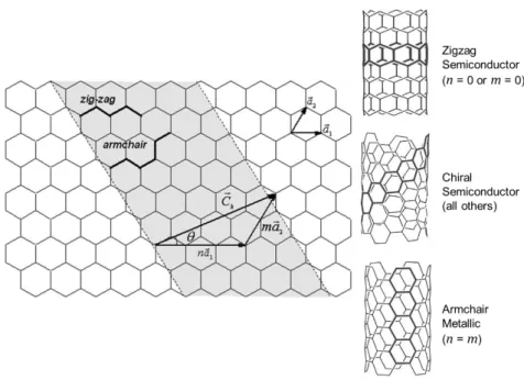
Fig.1-2 Chiral vector on a graphene sheet and possible configurations of CNTs [10].
Fig. 1-3 Schematic illustration of nanotube structures: (a) armchair, (b) zigzag and (c) chiral. The cylinders capped with a half of a fullerene molecule are also shown [14].
-5-
The properties of CNTs are strongly dependent on their structures, which are typically described in term of a helicity or chirality. The chirality at which the graphene is rolled can be defined by a chiral vector Ch and a chiral angle θ. The Ch is presented in the term of the lattice translational indices (n, m) where n and m describe the number of the repeating unit in the chiral vector, and the unit vectors 𝑎⃗1 and 𝑎⃗2 of the hexagonal lattice correspond to a cross section of the nanotube perpendicular to the long axis.
2
1 ma
a n
Ch (n and m are integers, 0 m n) (1.1) Chiral angle θ is defined as the angle between the vectors Ch and a1, with values of θ in the range 0 m 30.
m nm n
m n a
C a cosθ C
h h
2 1 2
1
2
2 (1.2)
The radius of the CNTs is given by L/π, in which L is the circumferential length of CNTs:
L/π b
2 (1.3) m nm
a n C C C
L h h h 2 2 (1.4) There are three types of structures: the armchair (n = m), zigzag (n = 0 or m = 0) and chiral (n ≠ m). The chirality of a nanotube is significantly important for its electronic properties. Armchair CNTs are metallic, while other configurations provide semiconducting character [10, 14-16].
-6- 1.2.2 Manufacturing methods
CNTs can be manufactured by different methods which are divided into two main groups: high-temperature evaporation using arc discharge or laser ablation, and chemical vapor deposition (CVD) or catalytic growth processes. The produced CNTs with high purity, large amount, uniformity and low cost are highly required for the production.
Schematic representation of these processes is shown in Fig. 1-4.
Fig. 1-4 Schematic illustrations of methods used for CNT production: (a) acr discharge, (b) laser ablution and (c) chemical vapor decomposition (CVD) [17].
-7- Arc discharge method
This method was firstly developed to produce both SWCNTs and MWCNTs. The electric arc discharges have a diameter range from 5 to 20 nm, and the gap between electrodes, which consist of graphite, is around 1 mm. The production requires a low- voltage (~12 to 25 V) but high temperature (> 5,000 °C) under an inert gas atmosphere, e.g., argon and helium. Although this method is tangled with poor control, it is possible
to selectively grow SWCNTs or MWCNTs by controlling the variation of parameters, e.g., temperature, pressure, gas species and catalyst, employed in this technique [6, 14]. The obtained CNTs are short with diameters of 1.2-1.4 nm (SWCNTs) and 1-3 nm (MWCNTs).
Laser ablation
A graphite target is vaporized by laser irradiation under an inert gas atmosphere at a high temperature (1,200 °C). The received CNTs are very pure, but the production rate is low because only bundles of SWCNTs with 5-10 μm in length and 1-2 nm in diameter are being produced. Therefore, it is not effective for a large-scale synthesis [18, 19].
-8- Chemical vapor deposition (CVD)
This technique is an alternative method in which CNTs are grown using a catalyst.
The nanotubes are produced from the decomposition of a continuous carbon containing gas on the substrate with the presence of a metal catalyst (iron, nickel or cobalt). The precipitation of carbon from the saturated metal particles leads to the formation of CNTs.
The produced CNTs with controlled length and diameter can also be achieved via this CVD method. Long nanotubes with diameters ranging from 0.4-5 nm (SWCNTs) and 10- 200 nm (MWCNTs) can be obtained. Due to the continuous supply of a gas, a high purity CNTs can be produced in a large scale with a good yield. Therefore, it has a capability to scale up into a commercialized level [20].
All of these methods are still under development and every technique provides diverse advantages and disadvantages for the quality and manufacturing methods.
1.2.3 Properties of CNT
CNTs have gained much interest due to their remarkable physical properties with an extremely high aspect ratio. Furthermore, their low density (800-1,800 [kg/m3]) should be focused for high potential applications. Details of the properties are given below.
-9- Mechanical properties
CNTs have been recognized as one of the strongest materials in the world because of the covalent sp2 bonds between the individual carbon atoms. A perfect arrangement of the carbon-carbon bonds along the cylinder axis provides significantly high mechanical properties. The properties of CNTs have been intensively studied by both experimental measurements and simulations [8, 14]. The elastic modulus is determined by three kinds of forces: two types of strong intralayer carbon-carbon bonds and one weak interlayer interaction (only for MWCNTs). The intralayer forces consist of strong σ- bonding and π-bonding between carbon atoms, which offer CNTs very high modulus and tensile strength. It has been reported that Young's modulus of SWCNTs is in the range of 0.32-1.47 TPa, while that of MWCNTs is over 1TPa. Furthermore, the tensile strength in the range of 10-200 GPa for MWCNTs, which is 10 to 100 times higher than that of the strongest carbon steel (1.2 GPa) [8, 12, 14, 21]. Due to the extremely high strength of CNTs, they can bend without breaking. Therefore, they give possibilities for the use of highly elastic and very strong composite fillers.
Thermal properties
CNTs are of the great interest for not only their excellent mechanical properties,
-10-
but also their thermal properties, in particular, high thermal conductivity. Theoretical predictions have revealed that CNTs are very good thermal conductors along the tube axis but good insulators in the transverse direction [22]. In the classical Debye model, the thermal conductivity depends on the following three parameters: the phonon free path, the phonon velocity and the phonon heat capacity. Due to the nanoscale structure of CNTs, the quantum effect is expected, and thermal conductivity shows evidence of 1D- quantization of the phonon band structure. The thermal conductivity of a defect-free CNT can be as high as 6,000 W/mK, while the thermal conductivities of diamond and graphite crystal are around 3,320 and 2,000 W/mK, respectively [23].
Electrical properties
CNTs possess unique electrical properties with a large band gap, and the properties are closely related to their molecular structure [4]. More specifically, a CNT’s band structure depends on its chirality as previously mentioned in 1.2.1. Armchair CNTs (n = m) show metallic conducting behavior, while zigzag (n or m = 0) and chiral (n ≠ m) are semiconductors [10, 14, 15, 24]. Additionally, MWCNTs are more complex than SWCNTs because each of their carbon shells can have a different chirality and electronic character. The metallic properties of the MWCNTs are due to their multiple-shell structure
-11-
consisting of tubes with various electrical properties. In general, however, most MWCNTs act as a good one-dimensional conductors [25]. Moreover, MWCNTs are predicted to have ballistic electron transport at room temperature, i.e., zero resistance along their length. Therefore, they can have conductivities several times greater than metals such as silver and copper [26].
Optical properties
The experimental measurements of the optical adsorption of a bundle of SWCNTs demonstrate that there are several absorption peaks. Each peak is related to the geometry of CNTs. The peak absorbance strongly depends on the CNT diameter and its chirality [27-29]. Since CNT thin sheets with low absorption from the UV region to the near-infrared can be manufactured, a great interest has been focused to produce transparent electrodes.
1.3 Polymer composite containing CNTs
Polymer composites, which consist of a polymer matrix with nanofillers, are greatly interesting and researched areas in nanotechnology because they have demonstrated their potential as high-performance materials. In this dissertation, CNT is
-12-
considered as one of the most interesting nanofillers for future applications. However, in spite of superior properties of CNTs combined with their low density and high aspect ratio, the way to use this nanofiller is not easy. Because of their non-reactive surface, CNTs have a bond with a polymer through physical interaction rather than chemical interaction, resulting in a weak interaction between a polymer and CNTs, which limits the efficient load transfer [30]. Besides, CNTs are difficult to be dispersed individually in a polymer matrix because they form bundles due to strong van der Waals interaction between individual tubes. The origin of the attractive force between neighboring tubes is the π-π interaction that causes a high van der Waals force, leading to an agglomeration of CNTs [1, 5, 31].
In order to disperse CNTs individually and uniformly within a polymer without destroying their high aspect ratio and integrity, several methods are employed such as functionalization of CNT surfaces by strong acid or solvents, the use of polymers to coat the CNT surfaces, in-situ polymerization, ultrasonic dispersion in solution, melt processing, the use of surfactants and so on. These methods allow CNTs to interact better with a matrix and thus overcome the van der Waals interaction between each nanotube.
-13-
1.3.1 Preparation of polymer composite containing CNTs
Several processing techniques are presented for preparing polymer composites containing CNTs. A good filler dispersion is required to achieve an effective utilization of CNTs in composite applications. Commonly, there are three methods for preparation.
Melt-blending
This technique is an effective method for introducing fillers into a viscous polymer melt. High temperature and high shear force are required for this technique to enhance the dispersion of fillers. The advantages of this method are as followed; (1) the filler can be dispersed into the polymer directly without the use of a chemical solvent and (2) the re-agglomeration of fillers is prohibited by the high viscous polymer. Moreover, this method is suitable for current industrial manufacturing. Many studies have shown the successful application of melt-blending in dispersing CNTs into various polymer matrices, e.g., polycarbonate (PC) [32], polypropylene (PP) [33] and polyamide 6 (PA6) [34, 35].
Furthermore, melt-blending can be performed in two ways: (i) direct incorporation of CNTs into a polymer during melt-mixing and (ii) dilution of a masterbatch, i.e., a polymer composite with a large amount of CNTs. At both cases, the mixing performance is strongly influenced by processing parameters such as mixing temperature, mixing time
-14- and applied flow field [32, 36, 37].
Solution blending
This is the most common method in an experimental scale for fabricating polymer composites, which involves three steps: (i) dispersing CNTs into a suitable solvent, (ii) mixing CNT suspension with a polymer and (iii) evaporating the solvent.
This technique effectively provides relatively well-dispersed CNTs in a polymer matrix under high-power ultrasonication for a period of time. Note that high-power ultrasonication may shorten CNT length, which is disadvantageous for the composite properties [38]. Normally, CNTs tend to form bundles because of van der Waals forces and physical entanglements between the tubes. The presence of CNT aggregates makes these fillers insoluble in a solvent. In order to solve this drawback, the introduction of a functionalization of the CNT surface is used to enhance the interaction between fillers and a host matrix. On the other hand, the surface properties of CNTs can be impacted negatively by solution blending, and the scale-up should be concerned because of the residue chemical solvent [38, 39].
-15- In-situ polymerization
The fabrication starts by dispersing CNTs in a monomer followed by polymerizing monomers. This process is an essential method for preparation of thermoset and rubber-based composites. For instance, an epoxy nanocomposite has been extensively studied using this technique, where CNTs are firstly dispersed in the precursor resin and followed by curing by hardener [40, 41]. The advantage of this process is that polymer chains can be grafted on the CNT surface, which gives a good dispersion of CNTs and a good interfacial strength between them. It should be noted that the viscosity of a polymer medium increases, which may limit the degree of polymerization [40-44].
1.3.2 Properties of polymer composite containing CNTs Mechanical properties
The unique structure of CNTs and their high aspect ratio, low density and superior mechanical properties provide an outstanding reinforcing ability for polymeric materials. In order to efficiently increase the ability, the load transfer between CNTs and a polymer matrix should be considered. If a load is effectively transferred to CNTs, the modulus will be similar to that of the composite containing randomly oriented short fibers, which shows tremendously high modulus and tensile strength [5]. The addition of CNTs
-16-
into a polymer is expected to enhance the Young’s modulus and tensile strength significantly with a relatively small amount. For example, Breuer and Sundararaj found 25% improvement in the tensile strength of PS by 1 wt.% of MWCNTs [31]. Dondero et al. prepared PP/MWCNT composites using the melt-mixing method followed by melt- drawing, and found that the toughness and modulus of PP increase about 32 and 138%, respectively, with 0.25 wt.% of MWCNTs [45]. On the contrary, in many cases, the elongation at break is decreased after the addition of CNTs [46, 47].
The tensile modulus and strength of CNT-filled polymer composites are strongly influenced by the CNT content, dispersion state and alignment. However, the experimental results at low CNT loadings usually stand far behind the theoretical predictions from the rule of mixture such as the Halpin-Tsai model [48]. This model is generally used to predict an elastic modulus of reinforced composites and can also be used to describe a stiffening effect of the CNT or nanofillers with large aspect ratio in polymer nanocomposites.
f f
V 1
V D L 2 1 E E
p c
(1.5)
where Ec and Ep are moduli of the composite and polymer matrix, respectively, and Vf is the volume fraction of fillers (CNT in this case). L and D are defined as diameter and length of CNTs. is the filler orientation efficiency factor, which is defined by
-17-
E E
2
L D
E 1 E
p f
p f
(1.6)
where Ef represents the Young’s modulus of the filler.
Haggenmueller et al. demonstrated that the tensile modulus of PE fiber was enhanced from 0.65 to 1.25 GPa with the addition of 5 wt.% SWCNTs, while the Halpin- Tsai model predicts the modulus to be around 16 GPa at the same filler loading [49]. At higher CNT loading, the viscosity of a composite becomes high, which limits the ability of the improvement and resulting in void defect [41]. The difference between the prediction and experimental results is caused by imperfect dispersion of CNTs and poor load transfer. Additionally, the modulus of agglomerated CNTs is lower than that of isolated CNTs, because the agglomerates have small aspect ratio combined with poor dispersion in a matrix. They result in insufficient stress transfer, leading to a composite with low mechanical properties. Hence, extremely high modulus and strength without losing in elongation at break can be achieved only by a proper mixing.
Electrical properties
The utilization of CNTs to improve electrical properties of polymer composites has been successfully realized. It is well known that a polymer is an insulating material which is desired for many applications. Nevertheless, due to the rapid growth of electronic
-18-
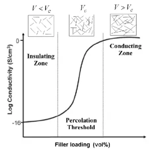
applications, conductive plastic parts are also required in electric devices. In fact, conductive polymers can be obtained when the filler content exceeds a critical value, known as a “percolation threshold”. At the percolation threshold, a three-dimensional conductive network is formed, leading to a sharp jump in the conductivity by several orders in magnitudes [12, 32, 50], as shown in Fig. 1-5.
Fig. 1-5 Electrical conductivity as a function of CNT loading. When the filler content exceeds the critical filler content (Vc), the insulate-to-conductive transition will occur.
Presently, several fillers such as carbon black (CB) and carbon fiber (CF) are employed to improve the conductivity of a polymer. However, high loadings of such fillers are often needed to gain conductive materials. Furthermore, it increases the final
-19-
cost of the materials. In contrast, CNT/polymer composites exhibit an extremely low percolation threshold, which is attributed to the high aspect ratio and nanoscale dimension of CNTs. Consequently, a conductive material with a small amount loading is possible to achieve while the other performances of a polymer can be maintained.
The percolation threshold of polymer composites containing CNTs is affected by aspect ratio, dispersion and alignment of CNTs. In general, the percolation threshold is reduced by good dispersion [22]. This topic has been studied by Du et al. using a series of SWCNT/ poly(methyl methacrylate) (PMMA) composites, where the degree of CNT alignment was controlled by the melt spinning. At a constant SWCNT concentration, e.g., 2 wt.%, it was found that high orientation of fillers significantly reduces the electrical conductivity of composites, which is attributed to the fewer contacts between SWCNTs, resulting in a higher percolation threshold [51, 52]. Besides, a chemical functionalization is widely used to improve the electrical properties of composites. Valentini et al. indicated that the amine-functionalized SWCNTs in an epoxy matrix allow transportation of intrinsic charges, leading to a good electrical conductivity [53].
Rheological properties
Rheological properties of polymer/CNT composites are very important to
-20-
understand the structure and their processability. In particular, rheological responses in the low-frequency region should be focused because they are sensitive to the structure, and thus have a close relationship with their electrical and mechanical properties in the solid state. In contrast, processability can be estimated roughly from the responses in the high-frequency or high shear rate region [54]. It should be noted that a significant change in the melt rheological behavior, i.e., a visible increment in viscosity and a sudden increase in yield stress, occurs around at the percolation. These effects are more pronounced in storage shear modulus G’ than in loss shear modulus G” [54, 55].
The non-terminal flow behavior, as often observed in composites with CNTs, is attributed to the formation of CNT network in a polymer matrix. As the CNT amount increases, nanotube-nanotube interactions begin to dominate, leading to the percolation and the formation of interconnected structure of CNTs, as shown by Pötschke et al. [32, 50, 56]. In other words, the rheological transition occurs from liquid-like (G’ω2) to solid-like viscoelastic behaviors at the percolation threshold (G’ and G” are independent of ω). It is well known that the rheological properties obey the power low near the sol- gel transition as follows.
m mc
aη (1.7)
c
b' m m
G (1.8)
-21-
where η* is the complex viscosity, G’ is the storage modulus, m is the CNT loading, mc is the rheological percolation threshold of the CNT loading, and, a and b are the critical exponents.
It is generally accepted that the rheological properties of composites also depend on dispersion and orientation of fillers and aspect ratio [57]. A good dispersion of fillers in a polymer matrix efficiently enhances G’ and also reduces the rheological percolation threshold [22]. It has been also shown that the contacts between nanotube and nanotube decreases with increasing the orientation of CNTs. Hence, it can be concluded that the viscoelastic properties of composites are sensitive to the orientation of fillers [57, 58].
Moreover, it has been shown that the rheological percolation threshold is sensitive to the temperature, implying that rheology reflects a combined network of the polymer chains and CNTs [58, 59] (not only the interconnection between CNTs).
1.4 Polymer blend containing CNTs 1.4.1 Polymer blend
Polymer blends, i.e., a mixture of at least two or more polymers, are generally used to develop a new material with different properties. The desired properties can be accomplished using this approach. Thermodynamically, there are two classifications of
-22-
polymer blends, i.e., miscible and immiscible blends, defined by the following relation [60]:
TΔS ΔH
ΔGmix mix mix (1.9) where Gmix is the Gibbs’s free energy of mixing, Hmix is the enthalpy of mixing and
Smix is the entropy of mixing. One phase will be obtained in a blend in the equilibrium state when the Gibbs’s free energy of mixing is negative. Though the entropy of mixing is always positive, the contribution is negligible because of the high molecular weight.
Therefore, the sign and magnitude of Hmix usually determine the sign of Gmix. Due to high molecular weight, as mentioned above, the mixing entropy of a blend is extremely low, which can be regarded as 0. Further, the mixing enthalpy is positive for most polymer pairs. Consequently, the sign of Gmix is positive, leading to phase separation for polymer- polymer blends. Therefore, most polymer blends show separated-phase morphology, e.g., sea-island structure and co-continuous structure. The phase morphology of a polymer blend plays an important role in the final properties. In other words, a polymer blend with desired properties can be tailored by controlling its morphology.
In this thesis, CNTs are further added in immiscible polymer blends. The introduction of MWCNTs into commercial thermoplastic blends can be found such as polyethylene (PE)/PC [61], poly(ethylene terephthalate) (PET)/poly(vinylidene fluoride)
-23-
(PVDF) [62], PP/acrylonitrile-butadiene-styrene terpolymer (ABS) [63], etc. Mechanical and electrical properties of polymer blends can be greatly enhanced by the addition of a small amount of CNTsdue to their superior structure.
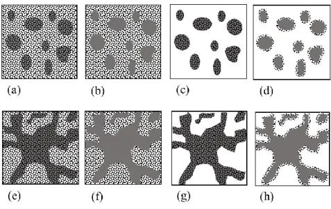
When CNTs are introduced into a polymer blend, three cases of filler dispersion can take place (Fig. 1-6): (i) CNTs are randomly dispersed in both polymer phases, (ii) CNTs selectively reside in only one of phases and (iii) CNTs localize at the interface between phases [64-67]. In order to control the structure, the recipe of a polymer blend and processing conditions have to be appropriately selected.
Fig. 1-6 Possible uneven distributions of CNTs in an immiscible polymer blend. (a) - (d) represent sea-island structure, while (e) - (h) show co-continuous structure with different CNT localizations.
-24-
It is noted that, although three types of the filler distribution can occur, the desired properties of polymer blends containing CNTs are usually obtained from two morphologies: (i) localization in one polymer phase [Fig. 1-6 (b, c, f and g)] and (ii) localization at the interphase between polymer phases [Fig. 1-6 (d and h)].
1.4.2 Localization of CNTs
As presented in Fig. 1-6, CNTs will reside in one phase or at the phase boundary.
There are two main factors to determine the localization of the fillers: thermodynamic and kinetic effects.
1.4.2.1 Thermodynamic effect
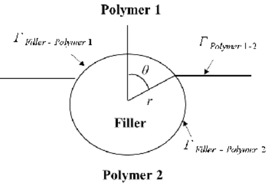
The selective localization of CNTs in a polymer blend is related to the difference in interfacial tensions between the filler and polymers. Furthermore, the interfacial tension is determined by the difference in polarity and surface free energy (Fig. 1-7) [68].
-25-
Fig. 1-7 Schematic representation of the interface between polymer 1, polymer 2 and filler.
Preferential localization of CNTs can be predicted by the wetting coefficient ωa
defined as Eq. 1.10 [68], that is obtained from the Young’s equation.
Γ Γ cos Γ
Polymer
Polymer Filler Polymer
Filler a
2 1
1 2
(1.10)where θ represents the contact angle, and Γ Filler-Polymer 2, Γ Filler-Polymer 1 and ΓPolymer 1-2
represent the interfacial tensions between the filler and polymer 2, the filler and polymer 1, and the polymers 1 and 2, respectively.
This equation describes the adjustment of wetting angle on filler surfaces, and is the most common approach to predict the filler location after melt blending.
As described by Sumita et al. [64], fillers will locate in polymer 1 at ωa > 1 and in polymer 2 at ωa < -1. Fillers will reside at the interface between two polymers at -1 <
ωa < 1. The last situation is possible to occur in a polymer blend composed of polymers
-26-
with a large interaction parameter or when the difference in the interfacial tension between filler and polymer is significantly small. This coefficient can be used as a thermodynamic indicator to predict the distribution of fillers in a specific area in a polymer blend with multiphase. Usually, interfacial tensions between polymers are estimated by the theoretical models, i.e., Wu [69], Owens-Wendt [70] or Girifalco-Good [71] equations (Eqs. 1.11-1.13). Those equations are based on the measurement of the surface free energy of each component.
dd dd pp pp Γ
2 1
2 1 2 1
2 1 2
1 4 (1.11) )
Γ 122( 1d2d 1p2p (1.12)
2 1 2
1
2
Γ (1.13) The exponents d and p represent the dispersive and polar contributions to the surface free energy. Such calculations, based on the Owens-Wendt equation, have been done by Sumita et al. for PE/PP, PE/PMMA and PP/PMMA blends with CB [64, 72], by Elias et al. for silica dispersed PP/polystyrene (PS) and PP/EVA blends [73, 74], and by Göldel et al. for MWCNT dispersion in PC/poly(styrene-co-acrylonitrile) (SAN) blends [75]. It is important to note that the surface free energy of a polymer is dependent upon temperature [68]. However, almost interfacial tensions between a filler and a polymer are evaluated at room temperature, while the morphology is decided in the molten state. It suggests that
-27-
the thermodynamic equilibrium state may be difficult to reach and kinetic effects, such as mixing protocol and viscosity, should be taken into account.
1.4.2.2 Kinetic effect
Kinetic effect is directly attributed to the mixing process. It is known that the dispersion state of fillers in a polymer blend is often different from the equilibrium one because of its high viscosity. Fillers may reside in a polymer that has a lower viscosity or melting point, even though it has a lower interaction with fillers than another phase.
Nevertheless, it has been shown that the localization can be changed by controlling kinetic factors.
Mixing protocol
The order in the component addition, i.e., mixing protocol, is important and has a strong effect on the final distribution of CNTs. Generally, fillers can be introduced into a polymer blend by several methods:
(i) All components are simultaneously mixed in a mixing machine. As mentioned previously, the melting point of a polymer affects the distribution of fillers. If one polymer melts at a temperature apparently lower than the other polymer,
-28-
fillers may localize into the first one. [76].
(ii) Two polymers are mixed together and subsequently introduced fillers into the melt blend.
(iii) Fillers are firstly introduced into one polymer, i.e., masterbatch, and diluted by another polymer.
Depending on the mixing orders, CNTs may transfer from one polymer to the other to reduce the free energy. For example, Zaikin et al. have varied the mixing order of polymer pairs with CB. They found that the mixing order significantly affects the localization of CBs, leading to different conductivity [77, 78]. Furthermore, Gubbles et al. studied the transfer behavior of CBs in co-continuous PS/PE blends as a function of duration of mixing. The CBs were firstly melt-mixed with PS, and then PE was further added. It was found that CBs tend to move from less preferred PS toward preferred PE phase with prolonged mixing, resulting in an obvious difference in resistivity. When CBs are localized at the interface, the resistivity is low. Then, the value gradually increases with the filler migration. With this strategy, an extremely low amount of CBs (0.4 wt.%) is enough to produce a conductive PS/PE blend. It implies that the preferential localization of fillers can be controlled by mixing condition [79, 80].
-29- Viscosity
The viscosity ratio of component polymers is one of the major factors to determine the morphology of a polymer blend. When the selective localization of fillers in one phase in a phase-separated polymer blend occurs, the viscosity ratio between two polymers is also changed concurrently, leading to a significant change and/or evolution of the blend morphology. Feng et al. and Liebscher et al. proved that the viscosity ratio of polymers is important to determine the final morphology of the blend [81, 82]. For example, the viscosity ratio of PP and PMMA affects the dispersion state of CBs in the blends. CB resides in the PMMA phase when the viscosity of PMMA is low or at the boundary when the viscosity is medium. When PMMA has significantly high viscosity, CB will be selectively localized inside the PP phase [81]. These results agree with the studies reported by Clarke et al. [83] and Zhou et al. [84]. Besides CB, Wu et al. have demonstrated that a different localization behavior of CNTs in poly(lactic acid) (PLA)/polycarprolactone (PCL) blends. They found that CNTs are localized in the PCL phase or at the interface when the viscosity ratio is high. In contrast, a localization of CNTs in PLA is detected at a low viscosity ratio [85].
Moreover, surface roughness and aspect ratio of fillers also play an important role in the transfer behavior of fillers. Recently, Göldel et al. purposed a “slim-fast
-30-
mechanism” which describes the impact of filler shape and aspect ratio on kinetic transfer between polymers [86]. The high-aspect-ratio filler, e.g., CNT, transfers from one phase to the other faster and more efficiently than low-aspect-ratio filler, e.g., CB [75, 86, 87].
This is because low-aspect-ratio fillers have more resistance during transfer and are trapped at the blend interface [64, 79], as illustrated in Fig. 1-8
Fig. 1-8 Distribution state of (a) low and (b) high aspect ratio fillers in polymer blend after melt mixing. Fillers are firstly dispersed in polymer 1 (white) and subsequently mixed with polymer 2 (grey).
1.4.3 Theoretical background of CNT transfer in polymer blend
During melt-mixing process, the transfer of CNTs from one phase to the other can take place in two steps: (i) direct contact between CNTs and the blend interface and (ii) CNTs transfer through the interface [88]. In general, the filler movement and
(a) (b)
-31-
localization can be induced by flow field and diffusion of fillers. At least in the latter case, the Brownian motion [67] is the driving force. The mechanism of CNT migration involves the combination of filler diffusion, shear induced collision and particle trapping during coalescence [88, 89]. The probability of the collision and coalescence strongly depends on the filler localization and blend morphology. In the case of sea-island morphology, these mechanisms can be used when fillers are located in the matrix. When fillers localize in the dispersed droplets, the transfer has to be provided by other mechanisms, which are still not understood.
From the concept of slim-fast mechanism, the subsequent transfer of fillers should be driven by the curvature of the blend interface, which is originated from the development of the wetting angle on the surface of fillers [86]. The mechanism is described in more detail by the following steps.
Diffusion
The important phenomenon to describe the CNT transfer is the Brownian motion.
For an ideal cylinder filler with high aspect ratio, the motion of a filler surrounded by a molten polymer is relatively complex due to translational and rotational motions of the anisotropic filler.
-32-
Generally, a diffusion coefficient D of spherical fillers by Brownian motion is expressed by the Stokes-Einstein equation:
η r π
k T D
M B
6 (1.14) where kB is the Boltzmann constant, T is the temperature, ηM is the viscosity of the medium and r is the radius of a spherical filler.
For a rigid rod filler, the rotational diffusion in a viscous liquid was theoretically discussed by Doi and Edwards [90]. The rotational diffusivity Dr is derived by the following equation:
ζ k T D
r B
r (1.15) where ζ r is the rotational friction constant, which is provided by:
1
2 2 1
2 2 1 2
2 1 2 4
3 1
1 1 1
2
1 2 1 1
3 2
/
/ M /
r
A A A A ln A A
A L A
πη
(1.16)
where L is the length of rigid rod and A is the aspect ratio (A = L/r). For A > 2, Eq. 1.16 is approximated as:
2
2 1
3
2 3
A ln
η L π M
r (1.17) Using integration by parts, a translational diffusion coefficient D that consists of two kinds of motions, i.e., parallel and perpendicular, to the rod’s long axis can be estimated.
η L π
L/r k Tln ξ
k T D
M B //
B
// 2 (1.18)
-33-
η L π
L/r k Tln ξ
k T D
M B B
4
(1.19) Since D// D , a rod can move more easily in parallel direction to the axis than in perpendicular. The D of a Brownian rod in an isotropic medium is the average of the diffusion coefficients D// and D.
D D
D // 2
3
1 (1.20) Finally, the translational motions of CNTs in a polymer melt can be explained.
Shear induced collision
Since fillers and polymers are moving during melt-mixing, a collision between a filler and the boundary of phases should occur. This phenomenon occurs obviously when CNTs are dispersed in a matrix and tend to move to the dispersed droplets. Based on the basic study on the droplet breakage and coalescence processes [91], the collision probability Pcol between two droplets after breakage is approximately given by Eq. 1.21 [92]:
Φ t
exp π t
exp t P
proc d proc
col
col 8 (1.21)
where tcol is the collision time, tproc is the mixing time, Φd is the volume fraction of the dispersion and is the shear rate of the mixing process.
.
.
-34- Particle trapping during coalescence
In this case, the coalescence between two droplets of a dispersed phase plays an important role in the transfer of the filler. Apart from the collision of a filler and the blend interface by external flow field, the coalescence process can be subdivided into three further steps [87, 89, 92].
(1) Free polymer droplets are moving and subsequently approaching each other, leading to a formation of a film between them.
(2) The film becomes thinner because the matrix is slowly drained away. Finally, the film is ruptured, which is attributed to the attractive van der Waals forces between two drops when it reaches a critical thickness.
(3) Since the film is ruptured, the coalescence will be completed by the development of neck between two droplets.
The coalescence probability Pcoa can be estimated by Eq. 1.22 and the probability Pdrain
of a drained matrix film between the drops:
P P
Pcoa col drain (1.22) With the ratio of the drain time tdrain to the collision time tcol, the probability of Pdrain can be approximated:
t exp t P
col drain
drain (1.23)
-35- The Pcol is obtained from Eq. 1.21 [92]:
t t t exp t P
col drain proc
col
coa (1.24) In fact, it is difficult to obtain tdrain by the empirical model because of insufficient data for the estimation. The duration of film drainage is frequently described by simulations.
Therefore, this mechanism should be kept in mind. The models and simulations still need to be further verified in experimental investigations.
1.5 Objective of this research
Due to its high aspect ratio with a combination of superior properties, CNT is a promising filler for a polymer including immiscible polymer blends to provide high- performance and novel functions. A variety of potential applications based on polymer blends containing CNTs has been widely established. Hence, this research field is presently one of the most explored areas in the material science and engineering.
It has been revealed from many studies that the transfer of CNTs from unfavorable phase to the other can occur during melt-mixing process, which strongly influences the morphology and localization of CNTs. Since the morphology directly decides the properties of composites, understanding and controlling the CNT localization are the keys to adjust the desired properties for new potential applications.
-36-
The objective of this dissertations is to study and control the localization of MWCNTs in immiscible polymer blends by adjusting the processing conditions.
Although the localization of CNTs was studied intensively, the method presented in this research is different from the previous works. In most previous studies, the dispersion state of CNTs is controlled by surface modification of CNTs. On the contrary, the method in this study is free from the modification procedure. Furthermore, the effect of MWCNT localization on the composite properties, i.e., mechanical and electrical properties, is considered. Four types of polymer blends are employed in this study: PC/PET, PC/PE, PC/ethylene-propylene copolymer (EPR) and PP/EPR blends. PC/PET is one of the most available engineering plastics used for housing of electric field. PP/EPR is the most important polymer blend in the commodity plastics, which is used in wide applications including automobile industry. PC/PE and PC/EPR are not conventional blends in industry. However, they are easy to characterize the morphology including the distribution state of MWCNTs.
Following this general introduction, the localization of MWCNTs in PC/PET blends is presented in Chapter 2. The effect of the preferential localization on the mechanical properties is reported. Contradictory transfer behaviors of MWCNTs during laminating and melt-mixing are discussed in Chapter 3. Meanwhile, the selective
-37-
adsorption of PE on the surface of MWCNTs is also shown in the same chapter. In Chapter 4, the effect of processing conditions on the localization of MWCNTs in PC/EPR and PP/EPR blends is investigated. Furthermore, the mechanical properties for composites with different distribution states of MWCNTs are also evaluated. Finally, the findings of this research are summarized in Chapter 5. It is expected that the finding in this research will affect the industry greatly.
-38- 1.6 References
1. L.S. Schadler, S.C. Giannaris, P.M. Ajayan, Applied Physics Letters, 73, 3842 (1998).
2. S.S. Ray, M. Bousmina, A. Maazouz, Polymer Engineering & Science, 46, 1121 (2006).
3. W. Li, A.K. Schlarb, M. Evstatiev, Journal of Applied Polymer Science, 113, 1471 (2009).
4. S. Iijima, Nature, 354, 56 (1991).
5. P.M. Ajayan, L.S. Schadler, C. Giannaris, A. Rubio, Advanced Materials, 12, 750 (2000).
6. R. Saito, G. Dresselhaus, M.S. Dresselhaus, Electronic Structure of Single-Wall Nanotubes, Imperial College Press and World Scientific, London, (2011).
7. P.C. Ma, N.A. Siddiqui, G. Marom, J.K. Kim, Composites Part A: Applied Science and Manufacturing, 41, 1345 (2010).
8. D. Qian, G.J. Wagner, W.K. Liu, M.F. Yu, R.S. Ruoff, Applied Mechanics Reviews, 55, 495 (2002).
9. C. Thomsen, S. Reich, J. Maultzsch, Electronic Properties of Carbon Nanotubes, Wiley-VCH, Weinheim, (2007).
10. M.S. Dresselhaus, G. Dresselhaus, R. Saito, Carbon, 33, 883 (1995).
11. J.C. Kearns, R.L. Shambaugh, Journal of Applied Polymer Science, 86, 2079 (2002).
12. B.P. Grady, Carbon Nanotube-Polymer Composites: Manufacture, Properties, and Applications, John Wiley & Sons, Hoboken (2011).
13. M. Scarselli, P. Castrucci, M.D. Crescenzi, Journal of Physics: Condensed Matter,
-39- 24, 313202 (2012).
14. E.T. Thostenson, Z. Ren, T.W. Chou, Composites Science and Technology, 61, 1899 (2001).
15. M.S. Dresselhaus, G. Dresselhaus, P.C. Eklund, Science of Fullerenes and Carbon Nanotubes, Academic Press, San Diego, (1996).
16. M. Meyyappan, Carbon Nanotubes : Science and Applications, CRC Press, Florida, (2005).
17. J.P. Gore, A. Sane, Carbon Nanotubes - Synthesis, Characterization, Applications, In Tech, Croatia, (2011).
18. A.G. Rinzler, J. Liu, H. Dai, P. Nikolaev, C.B. Huffman, F.J. Rodríguez-Macías, P.J. Boul, A.H. Lu, D. Heymann, D.T. Colbert, R.S. Lee, J.E. Fischer, A.M. Rao, P.C. Eklund, R.E. Smalley, Applied Physics A, 67, 29 (1998).
19. Y. Zhang, S. Iijima, Applied Physics Letters, 75, 3087 (1999).
20. Y.C. Choi, Y.M. Shin, Y.H. Lee, B.S. Lee, G.S. Park, W.B. Choi, N.S. Lee, J.M.
Kim, Applied Physics Letters, 76, 2367 (2000).
21. J. Bernholc, M. Buongiorno-Nardelli, J.L. Fattebert, D. Orlikowski, C. Roland, Q.
Zhao, Mechanical Properties and Electronic Transport in Carbon Nanotubes, Springer, Boston, (2002).
22. M. Moniruzzaman, K.I. Winey, Macromolecules, 39, 5194 (2006).
23. M.J. Biercuk, M.C. Llaguno, M. Radosavljevic, J.K. Hyun, A.T. Johnson, J.E.
Fischer, Applied Physics Letters, 80, 2767 (2002).
24. A.K.T. Lau, D. Hui, Composites Part B: Engineering, 33, 263 (2002).
25. Y.J. Kim, T.S. Shin, H.D. Choi, J.H. Kwon, Y.C. Chung, H.G. Yoon, Carbon, 43, 23 (2005).
-40-
26. A. Urbina, I. Echeverría, A. Pérez-Garrido, A. Díaz-Sánchez, J. Abellán, Physical Review Letters, 90, 106603 (2003).
27. H. Kataura, Y. Kumazawa, Y. Maniwa, I. Umezu, S. Suzuki, Y. Ohtsuka, Y. Achiba, Synthetic Metals, 103, 2555 (1999).
28. O. Jost, A.A. Gorbunov, W. Pompe, T. Pichler, R. Friedlein, M. Knupfer, M.
Reibold, H.D. Bauer, L. Dunsch, M.S. Golden, J. Fink, Applied Physics Letters, 75, 2217 (1999).
29. N. Minami, S. Kazaoui, R. Jacquemin, H. Yamawaki, K. Aoki, H. Kataura, Y.
Achiba, Synthetic Metals, 116, 405 (2001).
30. O. Lourie, H.D. Wagner, Applied Physics Letters, 73, 3527 (1998).
31. O. Breuer, U. Sundararaj, Polymer Composites, 25, 630 (2004).
32. P. Pötschke, A.R. Bhattacharyya, A. Janke, H. Goering, Composite Interfaces, 10, 389 (2003).
33. A.R. Bhattacharyya, T.V. Sreekumar, T. Liu, S. Kumar, L.M. Ericson, R.H. Hauge, R.E. Smalley, Polymer, 44, 2373 (2003).
34. T. Liu, I.Y. Phang, L. Shen, S.Y. Chow, W.D. Zhang, Macromolecules, 37, 7214 (2004).
35. W.D. Zhang, L. Shen, I.Y. Phang, T. Liu, Macromolecules, 37, 256 (2004).
36. P. Pötschke, A.R. Bhattacharyya, A. Janke, European Polymer Journal, 40, 137 (2004).
37. I. Alig, D. Lellinger, M. Engel, T. Skipa, P. Pötschke, Polymer, 49, 1902 (2008).
38. P.R. Sundararajan, S. Singh, M. Moniruzzaman, Macromolecules, 37, 10208 (2004).
39. W. Bauhofer, J.Z. Kovacs, Composites Science and Technology, 69, 1486 (2009).
-41-
40. J. Zhu, J. Kim, H. Peng, J.L. Margrave, V.N. Khabashesku, E.V. Barrera, Nano Letters, 3, 1107 (2003).
41. J. Zhu, H. Peng, F. Rodriguez-Macias, J.L. Margrave, V.N. Khabashesku, A.M.
Imam, K. Lozano, E.V. Barrera, Advanced Functional Materials, 14, 643 (2004).
42. W. Feng, X.D. Bai, Y.Q. Lian, J. Liang, X.G. Wang, K. Yoshino, Carbon, 41, 1551 (2003).
43. H. Huang, C.H. Liu, Y. Wu, S. Fan, Advanced Materials, 17, 1652 (2005).
44. N.R. Raravikar, L.S. Schadler, A. Vijayaraghavan, Y. Zhao, B. Wei, P.M. Ajayan, Chemistry of Materials, 17, 974 (2005).
45. W.E. Dondero, R.E. Gorga, Journal of Polymer Science Part B: Polymer Physics, 44, 864 (2006).
46. O. Meincke, D. Kaempfer, H. Weickmann, C. Friedrich, M. Vathauer, H. Warth, Polymer, 45, 739 (2004).
47. H. Zeng, C. Gao, Y. Wang, P.C.P. Watts, H. Kong, X. Cui, D. Yan, Polymer, 47, 113 (2006).
48. J.N. Coleman, U. Khan, W.J. Blau, Y.K. Gun’ko, Carbon, 44, 1624 (2006).
49. R. Haggenmueller, W. Zhou, J.E. Fischer, K.I. Winey, Journal of Nanoscience and Nanotechnology, 3, 105 (2003).
50. P. Pötschke, T.D. Fornes, D.R. Paul, Polymer, 43, 3247 (2002).
51. F. Du, J.E. Fischer, K.I. Winey, Journal of Polymer Science Part B: Polymer Physics, 41, 3333 (2003).
52. F. Du, J.E. Fischer, K.I. Winey, Physical Review B, 72, (2005).
53. L. Valentini, I. Armentano, D. Puglia, J.M. Kenny, Carbon, 42, 323 (2004).
54. L.A. Utracki, Polymer Composites, 7, 274 (1986).
-42-
55. J.M. Dealy, K.F. Wissbrun, Linear Viscoelasticity, Springer Netherlands, Dordrecht, (1999).
56. M. Abdel‐Goad, P. Pötschke, D. Zhou, J.E. Mark, G. Heinrich, Journal of Macromolecular Science, Part A, 44, 591 (2007).
57. F. Du, R.C. Scogna, W. Zhou, S. Brand, J.E. Fischer, K.I. Winey, Macromolecules, 37, 9048 (2004).
58. D. Wu, L. Wu, M. Zhang, Journal of Polymer Science Part B: Polymer Physics, 45, 2239 (2007).
59. P. Pötschke, M. Abdel-Goad, I. Alig, S. Dudkin, D. Lellinger, Polymer, 45, 8863 (2004).
60. P.J. Flory, The Journal of Chemical Physics, 10, 51 (1942).
61. P. Pötschke, A.R. Bhattacharyya, A. Janke, Polymer, 44, 8061 (2003).
62. M. Wu, L.L. Shaw, Journal of Power Sources, 136, 37 (2004).
63. R.A. Khare, A.R. Bhattacharyya, A.R. Kulkarni, M. Saroop, A. Biswas, Journal of Polymer Science Part B: Polymer Physics, 46, 2286 (2008).
64. M. Sumita, K. Sakata, S. Asai, K. Miyasaka, H. Nakagawa, Polymer Bulletin, 25, 265 (1991).
65. Y.P. Mamunya, Journal of Macromolecular Science, Part B, 38, 615 (1999).
66. S.S. Ray, S. Pouliot, M. Bousmina, L.A. Utracki, Polymer, 45, 8403 (2004).
67. H. Yoon, K. Okamoto, M. Yamaguchi, Carbon, 47, 2840 (2009).
68. S. Wu, Polymer Interface and Adhesion, Marcel Dekker, New York, (1982).
69. S. Wu, Journal of Macromolecular Science, Part C, 10, 1 (1974).
70. D.K. Owens, R.C. Wendt, Journal of Applied Polymer Science, 13, 1741 (1969).
71. S. Ross, I.D. Morrison, Colloidal Systems and Interfaces, Wiley-Interscience,
-43- New York, (1988).
72. M. Sumita, K. Sakata, Y. Hayakawa, S. Asai, K. Miyasaka, M. Tanemura, Colloid Polymer Science, 270, 134 (1992).
73. L. Elias, F. Fenouillot, J.C. Majeste, P. Cassagnau, Polymer, 48, 6029 (2007).
74. L. Elias, F. Fenouillot, J.C. Majesté, P. Alcouffe, P. Cassagnau, Polymer, 49, 4378 (2008).
75. A. Göldel, G. Kasaliwal, P. Pötschke, Macromolecular Rapid Communications, 30, 423 (2009).
76. Y. Mamunya, V. Levchenko, G. Boiteux, G. Seytre, M. Zanoaga, F. Tanasa, E.
Lebedev, Polymer Composites, n/a (2015).
77. A.E. Zaikin, R.R. Karimov, V.P. Arkhireev, Colloid Journal, 63, 53 (2001).
78. A.E. Zaikin, E.A. Zharinova, R.S. Bikmullin, Polymer Science Series A, 49, 328 (2007).
79. F. Gubbels, S. Blacher, E. Vanlathem, R. Jerome, R. Deltour, F. Brouers, P. Teyssie, Macromolecules, 28, 1559 (1995).
80. F. Gubbels, R. Jerome, E. Vanlathem, R. Deltour, S. Blacher, F. Brouers, Chemistry of Materials, 10, 1227 (1998).
81. J. Feng, C.M. Chan, J.X. Li, Polymer Engineering & Science, 43, 1058 (2003).
82. M. Liebscher, L. Tzounis, P. Pötschke, G. Heinrich, Polymer, 54, 6801 (2013).
83. J. Clarke, B. Clarke, P.K. Freakley, I. Sutherland, Plastics, Rubber and Composites, 30, 39 (2001).
84. P. Zhou, W. Yu, C. Zhou, F. Liu, L. Hou, J. Wang, Journal of Applied Polymer Science, 103, 487 (2007).
85. D. Wu, D. Lin, J. Zhang, W. Zhou, M. Zhang, Y. Zhang, D. Wang, B. Lin,
-44-
Macromolecular Chemistry and Physics, 212, 613 (2011).
86. A. Göldel, A. Marmur, G.R. Kasaliwal, P. Pötschke, G. Heinrich, Macromolecules, 44, 6094 (2011).
87. A. Göldel, G.R. Kasaliwal, P. Pötschke, G. Heinrich, Polymer, 53, 411 (2012).
88. L. Elias, F. Fenouillot, J.C. Majesté, G. Martin, P. Cassagnau, Journal of Polymer Science Part B: Polymer Physics, 46, 1976 (2008).
89. F. Fenouillot, P. Cassagnau, J.C. Majesté, Polymer, 50, 1333 (2009).
90. M. Doi, S.F. Edwards, The Theory of Polymer Dynamics, Clarendon Press, Oxford, (1986).
91. S.L. Ross, F.H. Verhoff, R.L. Curl, Industrial & Engineering Chemistry Fundamentals, 17, 101 (1978).
92. H. Potente, M. Bastian, Polymer Engineering & Science, 40, 727 (2000).
-45-
Chapter 2 Localization of CNTs in Polycarbonate and Poly(ethylene terephthalate) Blends
2.1 Introduction
Polymer blends have been intensively studied in both academic and industrial fields because of their potentially tailored properties with beneficial cost-performance [1, 2]. It has been established that a polymer blend has a capability to improve mechanical properties due to synergistic effect [3, 4]. Furthermore, properties of a polymer blend can be further enhanced by adding nanofillers such as organoclay, titanium dioxide and carbon black [5-7]. Carbon nanotube (CNT) is also a good candidate for polymer nanocomposites due to their excellent mechanical and electrical properties with a large aspect ratio [8, 9]. Besides, a selective localization of fillers is very important for the morphology design and property control of an immiscible polymer blend [10-12]. In general, filler dispersion in a blend strongly depends on both thermodynamic and kinetic effects [2, 13-16]. The thermodynamic effect governs the localization of fillers in one phase or at the interface, depending on the minimization of the interfacial tension between polymers and fillers. Thus, the filler location can be predicted. However, an equilibrium state of filler dispersion is uneasy to be obtained. Therefore, the kinetic effect, which
-46-
relates to the processing conditions and mixing protocol, becomes crucial in the preferential filler localization [17-19]. Moreover, fillers can act as compatibilizers to modify the morphology and properties of a polymer blend if they have a strong interfacial adhesion between two polymers. It has been reported that such fillers can reduce the interfacial tension, leading to an improvement of the compatibility of the different polymer species [17, 20, 21]. Pötschke et al. have investigated the localization of multi- walled CNT (MWCNT) for various blends prepared by melt-mixing process, where the main component was polycarbonate (PC) and the second component was polyethylene (PE) or polypropylene (PP) [11, 22, 23]. They found that MWCNTs preferentially localize in the thermodynamically preferred PC phase upon melt compounding. Besco et al.
studied a double percolation for PC/acrylonitrile-butadiene-styrene terpolymer (ABS) with modified layered-silicates and MWCNTs. They indicated that MWCNTs reside in the PC phase and the layered-silicates hinder the formation of an electrically conducting MWCNT network [24]. Rejisha et al. exhibited that the addition of a small amount of MWCNTs into the blend of poly(butylene terephthalate) (PBT) and PC significantly improves mechanical and thermal properties of the blend [25]. Additionally, the mechanical and electrical properties of poly(ethylene terephthalate) (PET)/poly(vinylidene fluoride) (PVDF) blends can be improved by the incorporation of
![Fig. 1-4 Schematic illustrations of methods used for CNT production: (a) acr discharge, (b) laser ablution and (c) chemical vapor decomposition (CVD) [17]](https://thumb-ap.123doks.com/thumbv2/123deta/6164414.1083506/15.892.154.740.593.891/schematic-illustrations-methods-production-discharge-ablution-chemical-decomposition.webp)