Improvement of Speech Recognition Performance for Spoken-Oriented Robot Dialog System Using End-Fire Array
6
0
0
全文
(2) finding is that the reason why the p巴rformance of the noise estimation is not good with a broadside a汀ay is because the mt巴rnal noise is always in-phase at the microphone array and. r -. r E. t-. ou 、nH ・ 巴目 。 ニ 』H ・ nv . 一 口 C 二 m ニ 二 t Ea ミu -M e - U 二 YA ? M ) 伊l・ げ山V e z '. of the SBSS bas巴d noise estimation and relate it to the direction of arrival (DOA) of th巴mt巴rnal noise. An important. y(f.τ) no(f.τ) !. thus it's DOA is approximately the same as that of th巴target speech. Consequently, in order to improve the performance of SBSS for noise estimation, we modify th巴 microphone. qατ). aπay s町ucture to discriminate DOAs of the target sp巴ech and the internal noise. In particular, we vary the angle of th巴 microphon巴 a汀ay to change the DOA of th巴 int巴rnal nois巴 (see釦gle em in Fig. 2). We determine th巴 optimal angle em that results in the best estimation of the internal noise vla a comput巴r simulation. To illustrate the effectiveness of. Fig.3. Block structure of the mixing and the unmixing at the fth frequency bin. the proposed approach, we evaluate the word accuracy in a dictation task in presence of both diffuse background noise. {ω00 (a) 主60∞ 〉、 U 5400D � 2000 lL. and robot internal noise, and show the improvem巴nt of the speech recognition performance.. 11. TARG釘SPEECH EX冗ACTION USING SEMI-BLIND SOURCE SEPAR氾10N. 。. 〉・、3. 守ω∞. We consider an acoustic mixing model where the number of microphones is J, and the number of int巴rnal noise. •••. L. J. ••• , � ,. \. \i). �. •••. 時nal nj(μ) = [n (f, T),.. ., n (f T)f (the number of internal noise signals is K) .百児observed signal vector at the internal noise sensors r(f, T) = [r, (f, T), , rL(J, T)f d巴pends only of the internal noise signal Th叩th巴observed signals at the microphone array and the. ,. internal noise sensors are given by,. (b). Time. [sl. Time. [s). 3.0. 2.0. � 60∞. (see Fig. 3). Let J denotes th巴 frequ巴ncy bin number, and T denotes th巴 time-frame index number. The observed signal at the microphone aπay x(f, T) = , x (J, T)]T is a mixture of one target speech [x, (J, T), signal s(f,T), the background environmental noise signal , n e)(f T)]T, and the internal no即 ne(J,T) = [n O)(λT), sensors is. 1.0. 。. A. Acoustic mixing model. 24000 � 2000 lL. Small. l. Power. 田園園. L珂e. Fig. 4. Speclrograms of (a) the observed signal at intemal noise sensors and (b) the true intemal noise signal at the microphone aπay. x(f, T) = h,(f)s(f, T) + ne(J T) + H2(J)nj(f, T),. (1). using the signal from the internal noise sensors to suppress the contribution of th巴mt巴rnal noise at the microphon巴a汀ay. r(f, T) = H3(f)n;(j, T),. (2). results in a deep deterioration of the estimated target speech. 川. •••. j. 一. where h, (J) = [ '\J), , h ' l (f)f is the column v削O contam川ning the transfer fl釦unctIωons凶s from the tar昭g巴目t s剖19na剖1 c∞om po叩n閃ent tωo each mi叩cro叩p凶hon巴久, H2メ(fρ) (υJ x K) i路s the matrix. c印O叩nta勾ining t出he t汀ransfl化巴r functions from the internal noise components to each microphone, and H3(f) (L x K) is th巴 matrix containing the transfer functions from the internal no,s巴components to each internal nois巴 sensor. quality.Thus, we need to estimate the internal noise signal at the microphone array from the observed signals (microphone. aπay and internal noise sensors).. B. Target speech extractioll. Th巴 observed signal vector at the int巴rnal noise sensors d巴pends only of the internal noise signal because the aerial vibration of th巴 target speech is not recorded by the internal noise sensors. Thus, w巴 can also assume that th巴mt巴rnal noise sensors observe only th巴 internal noise as vibrations transmitted through the chassis of the robot and not through the air. Figure 4 shows sp巴ctrograms of the obse円ed signal at the internal noise s巴nsors and the true internal noise signal at the microphone array. As showed in Fig. 4, the frequency characteristics of these signals di仔"er (differ巴nt types of sensors and propagation paths ). Therefore, directly. x. J, J x K,. y(J, T)= W, (J)x(J, T) + W2(J)r(J, T),. (3). q(f, T) = W3(J)r(J, T),. (4). and update th巴se matrices such that the components of y(f, T) = [Ys(f, T), Yn(f, T)f and q(f, T) [q,(J,T),.目., q (f, T)]T becom巴 mutually independent. In this paper, we use an iterative update of the unmixing matrices. Using the sup巴rscript .[kl to denotes a value at th巴. K. kth iteration, we have the following update rules. 971. - 1 99. =. In ICA, the sourc巴separation is performed by applying the. unmixing matrices Wj(J) (i 1 , 2 , 3 ) (of size J and K x K) to the observed signals. W�k+'l(刀= W�kl(J)一μ�Wlkl(J),. ( 5).
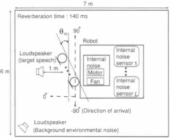
(3) 企W\k+11(f)= (1ー〈φω(f,T)川yH(f, T)欣I)T)W1tlげ), 企W�k+11(f)= (1- (φω(f,T)川,yH(f,T)川T)W�kl(j) 一((φω(J,T)川qH(f,T)[kl)T)W�kl(凡 ßW�k+11(f) = (1ー〈φ(q(f,TJlkl)qH(f, T)[kl)T)同l(j),. (6). optimized by ICA [8], and wDS(f,O) is the coe伍clent vector of the OS aσay which is de自ned by. (7) (8). サ?11f,81= 叫L一帆f jN)!sid sin Ojc),. L. wh巴re μis the step size parameter, 1 is an identity matrix, OT denot巴s a time-averaging operator, and MH denot巴s hermitian transpose of malrix M. The appropriate nonlinear vector functionφ(・) is estimated from the data using a kemel based estimat巴 of the scor巴 function [5], Aft巴r convergence, the pe口nutation problem is resolved using the method com bining OOA 巴stimate and probability d巴nsity distribution estimate [ 6]目 川市巴n separatmg a pomt-source target spe巴ch and a non point sourc巴 noise, ICA estimates 巴fficiently the noise by steering a directional null in the direction of the target, whereas the speech estimate is of poor quality [7]. Thus we utilize ICA as an estimator for both 巴xt巴mal and int巴mal noises but not for the speech. Th巴se nOlse 巴stimates are given by. た(J,T) = W�(f)[O,Yn(j,T)]T, 主i(f,T) = -W�(f)W2(f)W�(f)q(f,T),. (9) (10). wh巴re X丸eμT吋) = [ぴ£庁伊削;??刊吋e)(λμT),... ,Xイ£巧je)(λT竹W is 出巴 凶凶帥tn町ma background 巴nVlronme叩ntal noαise signal vector, and Xi(f,T) =. [ぴ£巧ザ;1?tりi)(f,. 巴 V巴ctωor (both 巴白側5坑tJ日1m町mat匂ed a剖t the miにcro叩phon巴 町a勾y). N 巴飢削X幻t, noωlS臼 canc巴ling i陪s performed by appl旬ying a WF on 巴ach of t山he ml氏crophone a汀ay s幻ignals. The noise 巴stimates used in the WF are obtained by adding th巴 contributions of both extemal and intemal noises at the microphones. =. •••. 主n(f,T) =走e(j,T) +主i(J,T), n. (11). wher巴主刈T) [x; )(j,T), ,;.;jn)(j,T)]T contains all the components of the estimated noise signal vecto仁The WF gain is design巴d as follows:. |Xj(f,T)12 g;(f,T) = -------'--' 川 IXj(f' T)I< +仰jUJ(λT)I三内. (12). where gj(f,T) is the WF gain at jth channel, and β lS a gain factor. The J enhanced speech signals 0包tam巴d by the Wiener filtering are. ^. ". ) X;(久T (WFLJ(f,T) = '1Ig J,T)lx ;(f, T)IL、 -:-,-一 一一. ;( ' n J '" 、f 0J� IXj(f,T) 1. s'; '". (13). Finally, the J Wiener-白Itered speech 巴stimates are merged into a single-channel signal by applying a OS beamformer as follows. SDS(f,T) = WDS(J,Ou? [S;WF)(f, T),.. . ,sjWF)(f,TW, D WDS(f,O) = [w; め(λ0), ,wT幻(μ)]T,. where!s is the sampling frequency, d is the microphone inter spacing, N is the OFT size, and c is the sound velocity The internal noise frequency charact巴ristics di汗巴r greatly depending on the robot actions. In particular the p巴riods when the robot does not mov巴 that contain only fan noise are very diff,巴rent from the periods when the robot moves as m巴chanical and motor noises can be heard. It was 巴xpen mentally reported in [9] that changing th巴 gain factor βof th巴 WF according to th巴 type of the intemal nois巴1mproves the speech recognition performance (The type of the intemal noise being detennined by using the control signals of the robot). In this paper, w巴 also consider 自xed and non fixed gain factor ß C. Problem. of semi-blind source separation. We conducted a preliminary experiment to con自rm the poor noise estimation perfonnance of SBSS. Figure 2 (Om = 0) depicts th巴 layout of the reverb巴ration room used in this experiment. We used a four-element microphone a打ay with an inter element spacing of 2.15 cm and three intemal noise sensors were installed inside of the robot. We used 10 utterances (female speakers, 16kHz-sampled signals) con voluted wi出 the impulse response that were recorded in this reverb巴rant room to simulate a user standing in front of the microphone a汀ay at a distance of one meter. The background environmental nois巴 signal is a noise recorded in an exhibition hall. The intemal nois巴 is a recording of the actual robot intemal noise (fan noise, mechanical noise and motor noise). Th巴 input signal-to-noise ratio (SNR) between the target s�ee h and the backgro�n environmental noise . _ _ between _ and the input SNR the targ巴t is set to 10 dB, speech and the intemal noise (refe打ed to as intemal SNR) is 16.6 dB. w巴 巴valuate the noise estimation perfonnanc巴 in SBSS on the basis of the sp巴ctral distortioll (SO) e(f) which is defined as follows:. ,:_. 吋). where SDS(f,T) is th巴 巴stimated target speech signal, Ou is the look dir巴ction which is estimated from the unmixing matrix. �. = 1叶j手� j. ). Ix n)(f,T) - ;.;jn)(f,T)12 ,. (17). wh巴re x\n) denotes the true nois巴 signal at the jth channel (the sum of the intemal and the background environmental noises). The smal1 SO indicates the high noise estimation perfonnance. Thus, if we achieve the perfect noise estima tion, the SO wil1 be minus infinity Figure 5 shows the SO averaged on the ten target speaker utterances. We can see that at low frequencies the noise estm】ate given by SBSS is severely distorted. IlI. PROPOSED 田市OD. (14) ( 1 5). (1的. A. Oνerv1ew. ln this s巴ction, we first analyz巴 the OOA of the intemal nois巴 to clarify the cause of the poor noise estimation perfor manc巴 in SBSS. As a result of this analysis, we confirm that. 972. nu nU 円ノ臼.
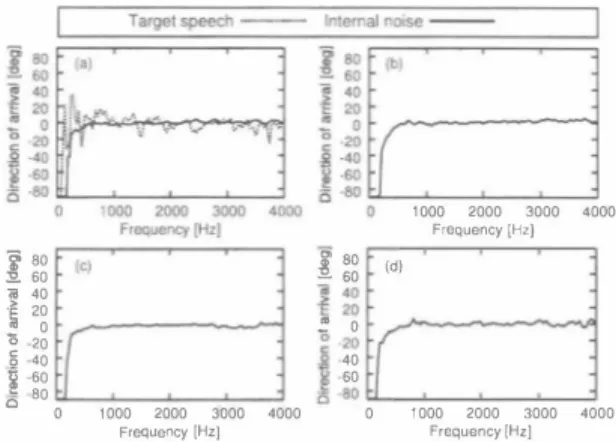
(4) nu nU nu nunu nu nu 『u nt 4E 4E n4 qu [∞ Z C O 一亡 O 目的 一句 一 冊 』担一uo a ω. Ezf(a). ii十一 6000. 0 08 06 000 02 04 O6 8 24. 2000 4000 Frequency. nu {官 官-B 長祖 E c g 古里 白. 。. 8000. [Hz). Fig. 5. Spectral distortion between the components of the true noise and 【he estimated noise (averaged on channels and utterances).. th巴 intemal noise is always in-phase at th巴 microphone a町ay. Bas巴d on this 自nding,w巴 propose a solution to overcome the problem of SBSS. B. DOA-based analysis. We first conduct an experiment to characterize the intemal noise DOA. The conditions are the same as th巴 prevlOus expenment As showed in Fig. 2, the axis used for measuring th巴DOA is such that the target speech for a user standing in front of the broadside array (Om = 0) has a DOA of zero degree The robot actions and fan noise (intemal noise) were recorded in four siluations (lype 1 to 4) while p巴rforming di釘巴renl movem巴nts that create additional mechanical and motor noises for short periods.Th巴 int巴mal nois巴 of typ巴 l designs th巴 shaking of the robot's head and is a relatively calm noise. But the other intemal noise types (2-4) design mov巴ments of the arrns and lhese nois巴s are loud to the point of masking the target speech. To estimate the DOA of the intemal nois巴 and 出巴 target sp巴氏h we use a minimum variance (MV) method. First, we calculate the estimat巴d power P(j,O) given by (18). P(f,O) = でア一一 」t aH(f,O)R一 ' (f)a(f,O) R(f) = E[z(f, T)Z H (f,T)],. (19 ). a(f,O) = [aI(f,O),ーー,a,(f,O)]T,. (20). 日j(/,O) = 巴xp (i27r(f /N)fsjd sin 0/ c),. •••. (21). wh巴re a(f,O) is the sleering vector, R(f) is【he correlation malrix, and z(f, T) = [z, (f, T), ,zJ (f,T)]T is the inpul signal vector (E[.] denotes an expectation operator). In this experiment, input signal vector is lh巴 true target speech signal or the intemal nois巴 signal at the microphone a汀ay. N巴xt, we vary the angle (J from -90 to 90 using a unit increment and select the value giving the largest IP(f,0)1 as the DOA of the input signal. The estimated DOAs for all the intemal noise typ巴s and the target speech ar巴 plott巴d in Figs. 6(a), 6(b), 6(c) and 6(d). Since the wav巴length in low frequencies is long, no DOA estimate methods can calculate the correctDOA. Thus, we do not consider the DOA result below 500 Hz. We. "". .g �� 60 [ 壱 40 主20 ご o 20 40 60 き -80 '000 2000 3000 4000 0 Frequency 1Hz]. ,. 000 2000 3000 4000. ,. 000 2000 3000 4000. Frequency I村zJ. (d). i. F,問uency 1Hz]. Fig. 6. DOAs of the intemal noise (a) type J and the target speech, (b) type 2, (c) type 3, (d) type 4. can see that the DOAs of all the internal noise types are approximately zero degree. Th巴 four types of nois巴s we consider are generated from various locations of th巴 robot (e・E・neck, left arrn, right arrn) but all of these noises are in phase at the microphon巴 aπay. Meaning that no matter the location from which the noises are generated their apparent DOA at the microphone aπay is zero degree. The reason of the above result is that when the robot makes a movement, th巴 microphone array vibrates with th巴 chassis.Thus the observed internal noise conlains vibrations that propagal巴 lhrough lhe robot chassis. Gen巴rally speaking, the sound velocity in the solid is faster than that in the a江. Therefore, the sound velocity of the intemal noise is fasl, and the time-difference-of-arrival of each microphone is smaller than that with propagalion through the air. Sinc巴 the intemal noise image is always in-phase at the microphone array regardless of the moving part of the robot, when the user slands in front of the robot with the broadside array, the DOA of th巴 intemal noise and that of th巴 target speech are lhe same see Fig. 6(a). C. Proposed structure. We consider that whil巴 using a speech-oriented human machine interface almost all users stand in front of the microphone array. Consequenlly, when using the broadsid巴 a汀ay, the target speech and lhe int巴mal noise have approx imately the same DOA (see Fig. 7(a)). In such situalion, ICA cannot estimate properly the intemal noise as steering a directional null in the spe巴ch direction also suppress the int巴mal noise (ICA cannot separate the sourc巴s which are spatially adjacent). To overcome this limitation, we modify the microphone a汀ay s汀ucture to discriminate the DOAs of the target speech and the intemal noise. In particular, the microphone array mounted outside of the robot varies from lhe broadside aπay (Om :; 0) to the end-fire array (Om :; 90). As a result, the DOA of the int巴mal noise is shifted to a di仔'erent dir巴ction of that of the targel speech while keeping the face-to-face relationship of lhe user and th巴 robot, s巴巴 Fig.7(b).Therefore, th巴DOA of the target speech. 973. -201一.
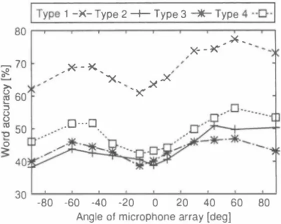
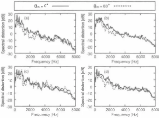
(5) (a). Microphone array. i. | Type 1 -)(- Type 2十Type 3十Type 4・-D-I. Robot. 80 I. 〉十-� Target. Internal noise. speech. image. for microphone. _70. m ゼ羽 Internal. _>母-�、. ポ. モァーシヨプ nOlse. 〉、. array. �コ. 60. �. 50. 8. (b). iJ 1J3. l. t. i. ×、. 、. 〉ぜ. X. _.x、、. ..x. e・0---ロ.. 0. �. l. 40. 30. -80. -60. -40. Angle. -20. 0. 01 microphone. 20. 40. 60. 80. array [deg]. Fig. 8. Word ac印racy for all the intemal noise types with di依rent angles of the microphone aπay Fig.7. (a) Conventional and (b) proposed microphone a汀"ay structures and the internal noise image for the microphone a口..y TABLE 1 EXPERDo唖NTAlCQND口τONS FOR百tE SPEECH R.ECOON円10N. test data. 2) Experimental result: We compared the di仔巴rent angles of th巴 microphone array on the basis of word accuracy, noise reduction rate (NRR) which is de白ned as the output SNR in dB minus the input SNR in dB, cepstral distortion (CO) which is a measure of the degree of spec汀al envelope distortion in the cepstrum domain [10]加d SO. Figure 8 shows the result of speech recognition test. We can see that word accuracy can be improv巴d by varying the angle of the microphone array. In pa口icular, word accuracy at Bm 60 degrees is obviously superior to that at Bm 0 degree for all int巴mal nois巴 types. We can achieve 14% (typ巴 1), 11% (type 2), 7% (type 3) and 13% (type 4) improvements of th巴 speech recognition result. NRR and CO (av巴raged on all target speak巴r utterances) ar巴 given in Figs. 9. W,巴also show the r巴sult of SO in Fig.l0. We can see that CO and SO at Bm 60 degrees is smaller than that at Bm 0 d巴gree for all intemal noise types, and that the NRRs for the cases of Bm 60 degrees and Bm 0 degree are almost th巴 same except for the type 3 intemal noise. This may be a clue to 巴xplain why th巴 improvement is th巴 least for type 3 noise. From these results, we can see that improving the SBSS nOlse 巴stimation performance results in an improvement of th巴 target sp巴ech extraction performance. This result also indicates that the improvement of th巴 sp巴巴ch recognition perfoηnance is mainly due to th巴 improvement of the CO.. =. =. ecoaer. and that of the intemal noise are no longer approximately the sam巴 Consequ巴ntly, it凶exp巴cted that the quality of the nOlse eS(Imate glv巴n by ICA improves. In th巴 following, we d巴termine the optimal angle of the microphon巴 array for the intemal noise of the robot and con自rm the improvement of the speech recognition performanc巴. IY. EXPER勘E悶AND RES札T A.. Experiment. J. = =. B.. J) Experimental setup: To confirm the 巴町ectiveness of varying the angle of the microphone a汀ay, w巴 conducted a computer-simulation-based experiment. We conform the conditions of the reverb巴rant room to the experiment of Sect. 2.3. However, the number of utterances is 100 (femal巴 sp巴akers), and w巴 us巴 four kinds of intemal noises. Th巴 intemal SNR of type 1 internal noise is 16.6 dB, type 2 is 4.5 dB, type 3 is 0.4 dB, and type 4 is 5.4 dB. Also, the gain factorβof the WF is fixed at 5 for all intemal noise types The experim巴nt IS repeat巴d with 巴leven di仔erent angle Bm: 士90,士60, :1:45 ,:1:30,土 10, O. The experimental conditions for the spe巴ch recognition show the Table 1.. =. =. E.λperiment 2 J) Experimental setup: We investigate the speech recog. =. nition perfoηnance at the optimal angle of the microphone array Bm 60 with optimizedβ. We conform the conditions of the reverberant room and speech recognition to th巴 巴xper iment 1 except parameterβ As mentioned in Sec_2.3, We change the β according to the noise typ巴 while the robot is moving. Values for stationary (ßI) and non stationary伊2) parts are glven ar巴Tabl巴 2.Thes巴 values are optimiz巴d bas巴d on word accuracy. 2) Experimental result: Figur巴 11 shows the result of the speech recognition test. We can se巴 that word accùracy at Bm 60 and optimizedβ(Proposed 2) is superior to that. =. 974. 円L ハU nJIH.
(6) eo Fha 凋U守 内d nJι {国 立 。 潟 』 E o --u コ 刀2 0 包 白 Z. Type. TABLE 1I. .8m=60.. 図。m::;:: 00. OA即FACTORβoFWF. 口Conventinal. 1. Type. 2. Type. 3. Type 4. •. Internal noise types. Proposed. 2. 事 2. ê 1.8. �凶 1.6. 百1.4 帽. �. 1.2. 8. 1. c.. Type. 1. Type 2. Type 4. Type 3. Type 1. Internal noise types. =. Fig. 9. Experimenlal resulls of (a) noise reduclion rale (b) cepslral distortion for Ihe cases of 8m � 0 degree and 8m � 60 degrees. 6000. 0 0. 4000. Frequency (HzJ. \1 VM. 2000. 0 8. 量剖. r. 司 -10. 一同. 句ぜ. 0. 1 0 0 0 0 0 0 0 0 3 2 1 1 2 3. 10. 同一 凹F 一. 2. 印 司 UH y o 1 柑 阿 「 市 O 『 hF h i ザ 1 V m 一 E Z c g 乞 B 2 3 冒 bHa的 。. 1 :: 帆 c) , ・, :\t.! i f. 2日00 4000 6000 Frequency [Hz}. 8000. =. Fig. 10. Spectral dislortion of internal noise (a) type 1,(b) type 2,(c) type 3, (d) type 4 for the cases of 8m � 0 degree and 8m 60 degrees. =. ,. at 8m 60 and βfìxed at 5 for all intemal nois巴 types (Proposed 1). Compared with the conventional microphone structure (Conventional), we can achieve 15% (typ巴1 ) 15% (type 2), 8% (type 3) and 16% (type 4) improvements of the speech recognition result at 8m 60 and optimized β(Propos巴d 2)ー. =. Y. CONCLUSION. [n this paper, we showed that the internal noise is aト ways in-phase at the microphone a汀ay because they are transmitted through a solid (the robot chassis here). Then we proposed to replace the broadside a汀ay by an end 自re array for improving both noise estimation and speech recognition perfoロnances. This proposed approach is not limited to robot application and can be easily以tended lo car. Type 3. Type 4. Fig. 11. Experimental results of word accuracy for the cases of the observed signal,8m 0 degree,8m 60 degrees wilh自xedβ� 5 and 8m � 60 degrees wilh optimizedβ. 9m- o'一ーーーー. 告. �. Type 2. Internal noise types. applications [13] b巴cause the road noise in car application is also transmitted through a solid (the car chassis). REFERENCES [1 ] J. Even, el 01., “Frequency domain semトblind signal separalion application to the rejection of internal noises," Proc. !nrernalional Con[erellce 011 AcouSlic Speech and Signal Processing, pp. 157160,2∞8 Loizou, Speech Enhallcement (2) P. Theoη' Prac� Gnd . lice. CRC P ress,2∞7 P. Comon,“lndependenl componenl analy剖5,a new conceptγS igllal 3) [ Processing. vol.36,pp.287-314, 1994 [4] M. Brandslein, el al., Micropholle Arrays Signal Processillg Tech lIiques and Applicalions, Springer-Verlag, 2001 [5] N. Vlass目,el al.,“Etlicien【 source adaplivily in independent analysis," IEEE Tralls. Neural NefWorks, vol.12, no.3, pp. 559-566, 2∞l [6) J. Even, el al.,“'An improved permutation solver for blind signal sep町ation based front-ends in robol audilion," Proc. IEEE/RSJ In ternational Conference on Inlelligenl Robols and Systems, pp. 21722177,2∞8 [7] Y. 11池山ashi, el al.,“Blind spatial sublraclion aπay for noisy en vironmenl," IEEE Trans. Audio, Speech, αnd Language Process illg, vol. 17. no. 4, pp. 650-664, 2∞9. (8) H . Saruwalari,el al., "Blind source separalion combining independenl componenl analysis and beamforming," EURASIP J. Applied Signal Porc., vol.2oo3, no.ll , pp. 1135-1146,2003 [9) J. Even,el al.,“Semi-blind suppression of inlernal noise for hands-free robot spoken dialog system," Proc. IEEE/RSJ Inlernaliollol Conρrellce on IllIelligent Robols and Syslems, pp. 658-663, 2∞9 [10)しRabiner,el al.,FUlldamenlals o[ ,peech月cogniliol1, Upper Saddle River,NJ: P問nlice HaU PTR,1993 [11] A. Lee, el .1.,“Julius? An open source realtime large vocabulary recog nition engine," Proc. EUI: Conf Speech Commul1. Technol., pp. 16911694,2∞ l [12] A. Lee, el al.,“A new phonetic tied-m印刷re model for e伍Clent decoding," Proc. Il1le円IOlio1101 Conference 011 Acous/;cs, Speech Gnd Signal Processil1g ,pp. 1269ー1272,2000 . [ 13] H. Saruwatari,et al., "Speech enhancement in car environment using blind source separation." Proc. International Conference 011 Spokell Langllage P,ひcessing, pp. 1781-1784. 2002. 975. nJ AU 円4.
(7)
図

+2
関連したドキュメント
The input specification of the process of generating db schema of one appli- cation system, supported by IIS*Case, is the union of sets of form types of a chosen application system
Moreover, to obtain the time-decay rate in L q norm of solutions in Theorem 1.1, we first find the Green’s matrix for the linear system using the Fourier transform and then obtain
W ang , Global bifurcation and exact multiplicity of positive solu- tions for a positone problem with cubic nonlinearity and their applications Trans.. H uang , Classification
She reviews the status of a number of interrelated problems on diameters of graphs, including: (i) degree/diameter problem, (ii) order/degree problem, (iii) given n, D, D 0 ,
It is suggested by our method that most of the quadratic algebras for all St¨ ackel equivalence classes of 3D second order quantum superintegrable systems on conformally flat
Here we continue this line of research and study a quasistatic frictionless contact problem for an electro-viscoelastic material, in the framework of the MTCM, when the foundation
In [7], assuming the well- distributed points to be arranged as in a periodic sphere packing [10, pp.25], we have obtained the minimum energy condition in a one-dimensional case;
Next, we prove bounds for the dimensions of p-adic MLV-spaces in Section 3, assuming results in Section 4, and make a conjecture about a special element in the motivic Galois group
