Japan Advanced Institute of Science and Technology
JAIST Repository
https://dspace.jaist.ac.jp/Title
Application of Data Compression Technique in
Congested Networks
Author(s)
Kho, Lee Chin; Ngu, Sze Song; Tan, Yasuo; Lim,
Azman Osman
Citation
Lecture Notes in Electrical Engineering, 348:
235-249
Issue Date
2015-10-29
Type
Conference Paper
Text version
author
URL
http://hdl.handle.net/10119/13783
Rights
This is the author-created version of Springer,
Lee Chin Kho, Sze Song Ngu, Yasuo Tan, and Azman
Osman Lim, Lecture Notes in Electrical
Engineering, 348, 2015, 235-249. The original
publication is available at www.springerlink.com,
http://dx.doi.org/10.1007/978-81-322-2580-5_23
Description
Proceedings of WCNA 2014, Book Title: Wireless
Communications, Networking and Applications
Application of Data Compression Technique in
Congested Networks
Lee Chin Kho1, Sze Song Ngu2,*, Yasuo Tan1, and Azman Osman Lim1 1Japan Advanced Institute of Science and Technology (JAIST),
School of Information Science, 1-1 Asahidai, Nomi City, Ishikawa, 923-1292, Japan
2Universiti Malaysia Sarawak,
Department of Electrical and Electronic Engineering, Faculty of Engineering, Kota Samarahan, Sarawak, Malaysia
Abstract. One of the viable solutions for reducing congestion in networks is
compression. Compression reduces data size and transmission time. The conventional compression techniques are mainly designed to compress data at application level of the Internet protocol suite and during network off-line condition. In this paper, a novel data compression based congestion control (DCCC) technique in transmission control protocol is proposed. The DCCC can be divided into two stages, which are the congestion detection and compression. In the first stage, congestion status identification is performed. If it is predicted that the congestion may appear in a particular network, then a sender that satisfies the compression conditions will send for compression. The second stage consists of the dictionary construction and data encoding to eliminate/reduce redundancy. The numerical result shows that the proposed technique can save up to 20% the network bandwidth when the block size of more than 16 Kbyte is used.
Keywords: Congestion control; data compression; transmission control
protocol; redundancy
1 Introduction
Wireless networks and future communication technologies such as the Internet of Things (IoT), Machine-to-Machine (M2M), and Long Term Evolution (LTE) are being developed rapidly in recent years. These have led to vast amount of data transmission, resulting in the overloading of communication networks. Networks, with limited bandwidth maybe congested. If the network is congested, the performance of the network in terms of the quality of service (QoS) and energy efficiency will be degraded. Therefore, the network congestions must be managed efficiently.
The conventional congestion control solutions relieve the congested network by decreasing the transmission rate of child nodes of a congested node. However, when the data is propagated back to the source in the case of serious congestion, packet loss
might still occur due to collision among nodes. Furthermore, transfer rate adjustment by congestion control techniques might raises difficulty in maintaining the network throughput stability. It is proposed in this paper that the actual transmitted data size in the network should be decreased to overcome this shortcoming. This can be achieved by the compression of data at the sender nodes.
Compression techniques in networks have started since a few decades ago, mainly during the data storage and data transmission processes. Compression techniques are stable, well developed and used in wide range of applications. Due to the space and time complexity of the compression algorithm, compression is mainly achieved in the application layer of Internet protocol suite and network off-line condition. Traditionally, the duration for large data compression and transmission is longer than the data transmission without compression. However, the data processing of recent machines are getting faster, compression is starting to be appealing for real-time low bandwidth network and wireless sensor network.
The congestion control technique with compression, Adaptive-Compression based congestion control Technique (ACT) has been described in [1]. Three compression techniques, Discrete Wavelet Transform (DWT), Adaptive Differential Pulse Code Modulation (ADPCM) and Run-Length Coding (RLC) are used in this studied. The network efficiency is improved with ACT, but it is limited in a specific environment and data format.
The real time adaptive packet compression scheme [2] is developed to improve the performance of high latency network with limited bandwidth. The scheme implements zlib compression library for compressing and decompressing the blocks of aggregated packet. Although this scheme can improve the packet drop rate in a heavy load satellite network, it operates only in the point to point connection.
In [3], a Fast Cross Layer Congestion Control (FCLCC) algorithm for compressed sensing technique is proposed. The FCLCC provides good compression and reduce the congestion duration greatly. However, the FCLCC is only suitable to solve the congestion problem in wireless sensor network.
The aforementioned researches depict that the data compression techniques can be implemented to solve the congestion problem. But, it is limited to a specify network environment and/or data type format. To the best of our knowledge, compression in congestion control is mainly implemented in wireless sensor network. This is because sensor data are usually spatial and temporal correlated. If the data is highly correlated, the compression performance is increased. To obtain highly correlated data and avoid the problem of packet timeout due to compression processing time, the compression is performed in the transport layer of sender nodes. Furthermore, this also allows the proposed scheme to be implemented in different type of networks and applications.
This paper proposes a new scheme, namely data compression based congestion control (DCCC). This scheme coordinates the data compression and TCP congestion control technique to address the congestion problem in the low bandwidth network. Our contributions are:
(1) The DCCC scheme is proposed to ensure the compression performance is beneficial to the congestion. For example, when the expected compression ratio (CR) for the block of data is higher than compression threshold, the data is sent without compression.
(2) In the DCCC, a new dictionary-based compression algorithm is proposed and implemented. This algorithm has lesser addition space complexity than the conventional dictionary-based compression algorithm.
(3) The DCCC scheme wills pre-determination the compressibility of the data. This can avoid the wasteful recompression for the data types such as JPEG, MPEG4, PDF, and M4A, which cannot give the good CR.
The arrangement of this paper is organized as follows. Section 2 devotes the architecture of DCCC. Section 3 discusses the proposed compression algorithm. The performance of the algorithm is evaluated in Section 4 and conclusion in section V.
2 Proposed DCCC Scheme
The DCCC scheme is implemented in transport layer of sender nodes. It is activated during the connection establishment, but only performs when network is congested. It will deactivate when the connection is disconnected.
2.1 DCCC Architecture
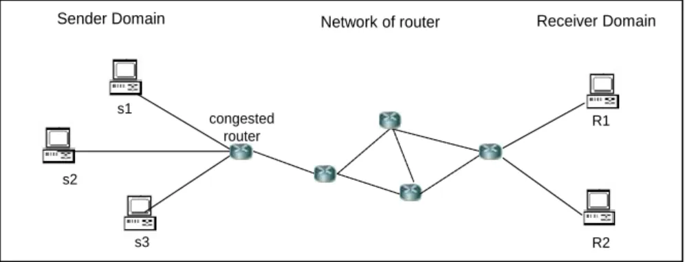
An example of DCCC performing scenario is depicted in Fig. 1. Multiple senders are transmitting their data packets to a router simultaneously. When the arrival rate of the incoming packet is greater than the rate of the router that can possible to send through, congestion is occurred. Then, the sender receives three duplicated acknowledgement messages from the receiver. The sender is responded by reducing the size of congestion window to decrease the transmission rate.
The DCCC is proposed to compress the outgoing data to avoid network congestion. Two main concerns of the compression algorithm in DCCC are additional memory needed during the compression and its ability to compress. A new compression algorithm is proposed and the detail of is discussed in the next section.
Fig. 1.An example of DCCC performing scenario
The architecture and session management of DCCC is showed in Fig. 2 and 4 respectively. Traditionally, when the data arrives at the transport layer, the protocols
s2
Sender Domain Network of router Receiver Domain
congested router s1 s3 R1 R2
such as TCP, UDP, SCTP and ATP start the process of data encapsulation. The application data is encapsulated into transport protocol data units called segment. In DCCC, the TCP is performed exactly same procedure during the normal condition. However, when a router is in the congested condition, the compression function at the sender will be operated if the compression activation condition is fulfill. Then, the compressibility of data arrives at the TCP protocol will be determined. If the data is un-compressible, it will forward directly to the segmentation process. If not, the data will be encoded before forward to segmentation process.
The session management of DCCC is performed during the connection establishment. After the connection is established, DCCC sends a control segment, ‘ACTIVATE’ to receiver. If the receiver consists of DCCC scheme, a segment of ‘ACTIVATE_ACK’ is returned to acknowledge the successful receipt of the segment. Then, the compression connection is established by sending the control segment of ‘ACTIAVTE_COMPRESSION’. If not, a segment of ‘ACTIVETE_NACK’ is returned. When the network is reached to a certain stage of congestion mode, the application data is directly sent to compression function in DCCC. The session management of DCCC is deactivated before the established connection is disconnected.
The congestion status is divided into three stages: moderate congestion, serious congestion and absolute congestion. These congestion stages are based on the traffic load of a congested router, which depicted in Fig. 3. During the moderate congestion, the router sent a notification message for enabling more packets to be forwarded. In the serious congestion stage, the router sends a notification message in on-demand fashion. At this time, the compression function in DCCC is performed. If the traffic load is still increasing until the absolute congestion stage, the formal TCP congestion control mechanism is performed.
Fig. 4. The session management of DCCC
2.2 Notations and Definitions Table 1. List of notations.
Symbol Description
x A character, which is set of hexadecimal number. Each character represents four binary bits (or a nibble), which is half of a byte (8 bits).
s A symbol, which is a group of two or more characters. If the symbol has two characters, then the maximum number of the symbols is 162or256.
ls A symbol length, which is the number of bits of a symbol. If the symbol has two
characters, then the symbol length is 2 characters X 4 bits = 8 bits.
c A codeword, which is a group of two or more concatenated symbols. If the codeword has two symbols and each symbol has two characters, then the maximum number of the codewords is 2562, which is equivalent to 65536.
lc A codeword length, which is the number of bits of a codeword. If the codeword
has two symbols and each symbol has two characters, then the codeword length is 2 symbols X 2 characters X 4 bits = 16 bits.
Symbol Description
C A code, which is a mapping from a symbol or a codeword to a set of finite length of binary strings.
A code length, which is the length of a code. If the code has bits, then we can encode at most 2of symbols and codewords.
D A dictionary, which is initialized to contain the single codeword corresponding to all the possible input characters. The dictionary is identical to the source data. E A entry, which is a unique codeword that formed from the concatenation of
symbols in the dictionary
So The size of source data that to be compressed
Sc The size of encoded data
P The sum of repetitions of all output symbols and codeword
Ps The sum of repetitions of all output symbols that were not compressed
Pc The sum of repetitions of all output codeword that have been compressed
Q The sum of entries in the dictionary
lcmax The codeword length that has the maximum number of bits of a codeword
lcmin The codeword length that has the minimum number of bits of a codeword
îc The codeword length that has the average number of bits of a codeword
Throughout this paper, the list of notations and definitions is given in Table 1.
3 Proposed Compression Algorithm
Lossless compression techniques are generally classified into two groups: entropy-based and dictionary-entropy-based. In the entropy-entropy-based, the shorter code length is assigned to the codeword that occur more frequently in the source data to eliminate the redundancy. This technique provides a good compression ratio (CR), but it requires high computation time and memory. Meanwhile, dictionary-based replaces the source data with a code to an entry in a dictionary. The most well known dictionary-based techniques are Lempel-Ziv algorithm and their variants. These compression techniques require an infinite dictionary size, which needs a huge memory. A new compression algorithm that requires lesser memory is proposed here to reduce the memory problem in the TCP.
3.1 Assumption and Constrains
To limit the memory requirements for the encoder and decoder, the amount of dictionary is bounded. Since the dictionary is going to transfer for decoding, the size of dictionary must be kept as small as possible. The dictionary is limited to 256 entries here.
The dictionary is filled with higher repetition codeword first regardless their position of appearance. Each of the codeword in the dictionary must fulfill the minimum repetition threshold (Rthre). The minimum threshold is given by
The codewords that less than Rthre shall not include in the dictionary because it will
causes the poor compression ratio.
The fixed length code is used in this algorithm. A fixed length code is a code such that i=j for all i and j.
Example 1: Suppose we have one symbol, {AB} and two codewords, {9F1B, 3E70B2}. In the fixed length code of 2 bits, the code would be C(AB) = 00, C(9F1B) = 01, and C(3E70B2)= 10.
A dictionary is initialized to contain the symbols corresponding to all possible input character. This dictionary is contained in both encoder and decoder, with the index from 0 to 255. As a result, the dictionary for codeword must start from =9 bits, and consists at least 512 entries. Since the first 256 entries are reserved for the symbols, only leave 256 entries are for the codeword.
3.2 Development of Proposed Compression Algorithm
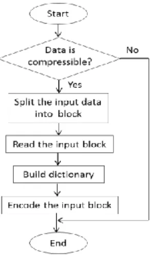
The process flow of proposed compression algorithm is showed in Fig. 5. When the TCP is in serious congestion stage, the compressibility of the source data is determined by compressing 1048 byte of data from the middle of the block. Although this method cannot provide an accurate prediction of the source data compressibility, it is enough to ensure the data is compressed or not. If the source data is compressed, it will send directly for segmentation. If not, it will be split into a specific block size.
The codeword is created while reading the block data. The codeword in the dictionary is just the expected codeword that shall be frequently used in the encoding process. This codeword is constructed by concatenating in the overlapping way based on the codeword length, lc.
Example 2: Consider a sequence data of A = {01ABABABAB01AB}. If lc. = 2,
the possible codeword become: 01AB, ABAB, ABAB, ABAB, AB01, 01AB. Each of the codeword is then counted by adding one during the concatenation or found the match between the block data and dictionary.
The codeword in the dictionary are then sorted descendingly based on repetition. If the codeword repetition that is less than Rthre, it will be removed from the dictionary.
After building the dictionary, the block data is encoded by matching the symbols or codeword from dictionary. If the maximum codeword length of block data exists in the dictionary, the codeword indices are used as the compressed output. If not, the shorter codeword length is matched until only one byte remaining. If one byte is left, the implicit part of the dictionary, the first 256 indices that are reserved for one byte symbols is used. Since the fixed length code is implemented, the beginning of symbol from the implicit part of the dictionary must add with zero. This process is repeated until the entire block data is encoded.
3.3 Derivation of the Compression Ratio
The performance of the data compression techniques is depended on the type of source data format that to be compressed. In order to compare different data compression techniques fairly, a factor, which is known as a compression ratio (CR) is commonly used.
In our paper, the compression ratio is defined as the ratio between the size of the source data (So) and the size of the compressed data (Sc ), which can be expressed as
(2) The amount of compression can also be stated as CR:1, where So can be assumed as a
string of N characters. This leads to So is equivalent to 4N bits.
Based on our proposed compression algorithm, Sc can be expressed as
(3) The term of (lc+8)Q is referred to the dictionary size that need to be transmitted for
decoding. The 8 bits is represented as the number of concatenated symbols in each of codeword. While, the P is coded data size and the P= Ps+Pc.
Example 3: Consider = 9 bits with source data of ABDE0378E4ABDEABDEAB DEABDE’. The So = 4 X 26 = 104 bits. The codeword that in the dictionary are c =
{ABDE, 0378E4}. Since the codeword length is variable, the average of codeword length, îc is equal to îc = (16+24)/2 = 20 bits. The dictionary size becomes (20 bits + 8)
2 = 56 bits. The coded data size is given by 9(0+5) = 45 bits. Therefore, the Sc= 56
bits + 45 bits = 101 bits. As a result, the CR = 104/ 101= 1.03.
3.4 Implementation Issues
To minimize the error that due to channel noise, the fixed length code is used. However, it creates the problem of enlarging the CR, when the compressed data consists of more Ps than Pc. To avoid this, the pre-determine compression performance
is performed. A new metric called total accumulative percentage (TAP) is introduced. If the TAP is less than some threshold, then the dictionary would not be able to
compress enough percentage of the data, which result in bad CR. The TAP is a heuristic solution. It can only use as an expected CR.
The TAP is calculated after building the dictionary and before the compression. First, the total codeword repetition (TCR) that generated from overlapped block data is calculated. Then the percentage of each codeword (PCi) is obtained by dividing the
codeword repetition (Ci) with TCR. The accumulative percentage (AP) for each
codeword in the dictionary is calculated by summing its own percentage (PCi) with
the percentages of all codeword ahead in the sorted dictionary (PCi-1). The AP of the
bottom codeword remaining would be referred as TAP. The AP can be described as
APi=PCi+PCi-1 (4)
The PCi can be defined as the fraction of a codeword repetition compared to the total
codeword repetition, which is given by
(5)
(6) The Smax and Smin are the sum to the maximum or minimum number of the square.
Example 4: Consider a dictionary with three entries ‘0ab158’, ‘9fb5’, and ‘7def83” with repetition of 100, 80, and 69 respectively. The `0ab158' and `7def83' is at the entries of i=1 and i=3 respectively with lc=3. The `9fb5' is at the entries of i=2 and
lc=2. The So=2,500 bytes, lmax=3 and lmin=2. Then, the Smax=0+1+4+9=14 and
Smin=0+1=1. The TCR= ( (2,500+1)/2)(2)(5)-14+1, which is equal to 12,492. The
PC1= (100 X 3)/12,492 becomes 0.024. Similarly, the PC2=0.012 and PC3=0.016.
Then, the TAP=0.024+0.012+0.016=0.052
The variable codeword length in this algorithm might take longer time to create the dictionary. The longer the lc, the time needs for determine the possible codeword
becomes larger. Therefore, the fixed codeword length and variable codeword length effect toward the CR is evaluated in the numerical analysis section.
4 Numerical Analysis and Discussion
In this section, code length, codeword length, and block size are analyzed. The code length is analyzed to determine the lower bound of the CR that this algorithm can be achieved. The codeword length and block size is analyzed to determine the optimal value for the proposed compression algorithm. Besides, the CR of the proposed compression algorithm is compared with others compression algorithm.
4.1 Code Length
When the code length is =8 bits, no dictionary is built. The must start from 9 bits onward. In this paper, the upper bound of CR in the proposed compression algorithm
is computed with the assumption of the sum of repetitions of all output symbols that were not compressed, Ps=0, the codeword length is fixed to lc=2, and total number of
entries in dictionary is fully utilize, where Et.=2-28. When Ps=0, it means perfect
compression, the So is only encoded by the codeword. In this case, the best
compression of CR that can achieve is given by
(7) Then, the upper bound of CR is given by
(8) The worst case of CR in the proposed compression algorithm can be computed when we assume the Pc=0. The worst compression of CR is given by
(9) The lower bound of CR is given by
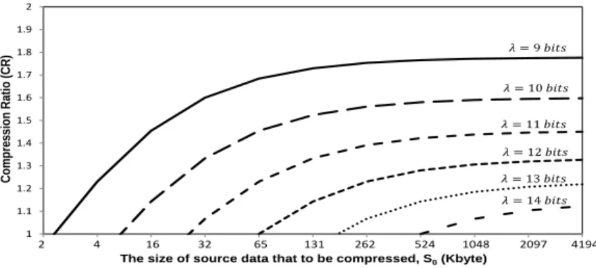
(10) The upper bound of CR for the proposed compression algorithm is showed in Fig. 6. The CR is decreased when the code length is increased. In order to have a better CR with fixed codeword length of 2, the 9 bits is the best selection. From the Fig. 6, the best performance that proposed compression algorithm can reach is 1.778. This means the compression algorithm can save up to 44% of the bandwidth in a network. Due to the fixed codeword length, it might also enlarge the compressed data size. The worst performance of this algorithm reaches is 0.889, which enlarge nearly 12% of the original data size. However, this problem can be solving by using the TAP pre-determination to reject compressing bad compression ratio data.
4.2 Codeword Length
The codeword length, lc is used to vary the length of the codeword string. The longer
of the codeword string, the more data bits can be compressed per symbol. However, the time needed to determine the possible codeword will be higher. The example of CR for fixed codeword length and variable codeword length are showed in Fig. 7(a) and Fig. 7(b) respectively. The test samples are from benchmark of the canterbury corpus [4] and silesia corpus [5]. The CR for book is the average of book1 and book2, obj is the average of obj1 and obj2, paper is the average of paper1 and paper2, prog is the prog1, prog2, and prog3.
From Fig. 7 (a), the lc=2 gives the highest CR among the others. This is because
when the lc is increased, the probability of false to match with the code is also
increased. In the variable codeword length, the minimum codeword length is equal to two and maximum codeword length is varied from 2 to 6 as shown in Fig. 7 (b). The CR for all of the test samples is over than 1. When the lc is increased, the compression
1 1.1 1.2 1.3 1.4 1.5 1.6 1.7 1.8 1.9 2 C ompres sion R ati o (C R )
The size of source data that to be compressed, S0(Kbyte)
2 4 16 32 65 131 262 524 1048 2097 4194
Fig. 6. The upper bound of CR for modified LZW algorithm
0.0 0.5 1.0 1.5 2.0 bib book geo news obj paper prog trans x-ray lc = 2 lc = 3 lc = 4 lc = 5 lc = 6 0.0 0.5 1.0 1.5 2.0bib book geo news obj paper prog trans x-ray lcmax = 2 lcmax= 3 lcmax = 4 lcmax = 5 lcmax = 6
Fig. 7(a) Fixed codeword length Fig. 7(b). Variable codeword length will become better, because the algorithm will try to search for the longest codeword to encode. However, this will take longer processing time. Likewise, the lc=2 for fixed
codeword length gives the nearly same CR with the variable of codeword length with
lmax=6. In this case, the lc=2 for the fixed codeword length is selected for the
following simulation.
4.3 Block Size
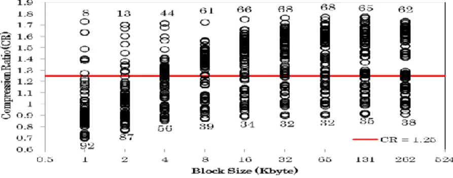
The CR of different source data size is simulated to determine the optimal block size for the proposed compression algorithm. 100 of test benchmark samples with 50% of binary format such as mp4, jpeg, and wmv, and 50% of text format such as txt, html, and .c are tested. The simulation result is showed in Fig. 8. The CR of 1.25 is used as a reference that needs to be achieved for the minimum CR. In this case, compressing each of the block data can at least save 20% of the network bandwidth.
From Fig. 8, when the source data is 8KB, 61% of the test samples give the CR with more than 1.25. When the block size is 32 KB and 64 KB, 68% of the test
samples can compress more than 20% of the original file size. However, the test samples that able to compress more than 1.25 of CR is decreased when the block size is more than 131 KB.
Fig. 8. The CR for 100 test samples in different block size
4.4 Comparison between Proposed and Other Compression Algorithms
The overall performance in term of average Bit Per Character (BPC) of proposed compression, Run-Length coding, Huffman coding, and Lempel–Ziv-Welch (LZW) coding are compared and showed in Table 2. The run-length coding uses the repetition based technique to compress the data. It is created to encode the data with a string of repeated symbols. Meanwhile, Huffman coding is the statistical based compression, where the probability distribution of character from source is used to develop the codewords. The LZW is the most commonly used of dictionary based compression. It compresses the data by using a dictionary to store repetitive codewords that occur in the source
Table 2. Comparison of BPC for different compression algorithm
File Name File Size RLE Huffman LZW Proposed book2 610856 8.16 4.83 3.78 4.55
news 377109 7.98 5.24 4.33 4.97 obj2 246814 8.05 6.33 4.68 5.43 paper1 53161 8.13 5.07 4.50 5.19 trans 93695 7.90 5.61 4.26 5.14 From the Table 2., the average of bit per character for proposed compression is lesser than the RLE and Huffman coding. However, the proposed compression needs more bits to represent a character than LZW.
To further investigate the addition memory requires by LZW and proposed compression, the following test environment is set. The simulation is performed in
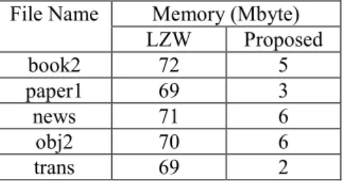
the GNU/Linux 3.13, 32-bit operating system, Intel Core 2 Duo 1.20GHz CPU, 4GB main memory, 160GB 66MHz hard disk. The C code of LZW and proposed compression are compiled with gnu C version 4.8.1. The simulation results are showed in Table 3. The additional memory needed by proposed compression is at least 10 times lesser than LZW. In summary, although the LZW performs better than proposed compression in general, it needs much more additional memory compare to proposed algorithm.
Table 3. Comparison of additional memory usage between LZW and proposed algorithm
File Name Memory (Mbyte) LZW Proposed book2 72 5 paper1 69 3 news 71 6 obj2 70 6 trans 69 2
5 Concluding Remark
In this paper, an application of data compression technique in congested networks, namely data compression based congestion control (DCCC) is proposed. The theoretical study showed that the proposed compression algorithm can compress up to 44% with the perfect compressible data. The numerical analysis showed that code length of 9 bits, codeword length of 2 and block size of 16kB are the optimal parameters of the proposed compression algorithm. Based on these parameters, the proposed compression algorithm is performed and compared with others compression algorithms. The results showed that the proposed compression is performed better than the repetitive and statistical based compression. The LZW is performed better than proposed compression, but it requires huge additional memory.
References
1. Hyoung, J., Jung, I. B.: Adaptive-compression based congestion control technique for wireless sensor networks. J. of Sensors. 10: 2920-2945 (2010)
2. Tan, L. S., Lau, S. P., Tan, C. E.: Quality of service enhancement via compression technique for congested low bandwidth network. In: Int. Conf. on Commun., pp. 71-76. Kota Kinabalu, Malaysia (2011)
3. Li, M., Jing, Y., Li, C.: Fast cross layer congestion control algorithm based on compressed sensing in wireless sensor network. In: Int. Conf. on Info. Tech. and Software Eng. Lecture Note in Elec. Eng. Springer. Vol. 210, pp. 869-876 (2013)
4. Ross, A., Timothy, B.: Canterbury corpus. http://corpus.canterbury.ac.nz/.Access 20 June 2014
5. Silesian University of Technology: Silesia compression corpus,