Study on Mechanical Properties of Rice
by-Products-Cement-Reinforced Sludge as
Banking Materials
著者
CHIEN PHAN THANH
学位授与機関
Tohoku University
学位授与番号
11301甲第18959号
TOHOKU UNIVERSITY
Graduate School of Environmental Studies
Study on Mechanical Properties of Rice
by-Products-Cement-Reinforced Sludge as Banking Materials
(米副産物とセメントによる固化スラッジの築堤材としての機
械的特性に関する研究)
By
Phan Thanh Chien
Abstract
Mekong delta is one of largest deltas in the world in terms of drainage basin size, freshwater discharge, and sediment flux annually. Due to flat topography and low flow velocity, annually the amount of deposited sediment on the river’s bed is very huge. Moreover, the waterway transportations in the delta always represents 60-70% of total transport volume. Furthermore, the delta is severely being affected by climate change, global warming, and upstream development such as building of the upstream hydropower.
From 2008, Vietnamese government has formulated a master plan and national target program to respond to the climate change and sea-level rise with the aim of creating irrigation systems, serving agricultural production in the new situation, contribute to social and economic development, eco-environmental protection and sustainable development. They are attempting to dredge more canals and rivers for improving irrigation system and for flooding control. Moreover, they are building many dykes to protect big cities and farmland. As results, huge amount of sludge has been discharging and huge amount of soil is needed for dyke constructions.
Moreover, the main business of the delta is agriculture and fishery industry. As results, agricultural by-products, rice husk and rice straw, are becoming complex problems. While rice straw is mainly left and directly burning on the fields after harvesting, rice husk is produced in large quantities in hundreds of thousands of rice mills all over the country. The burning will be continue as a habit of farmers on the coming years.
In generals, large amount of rice by-products, especially rice husk and rice straw, are generating. And, large amount of sludge is discharging due to the dredging works. These issues are significantly affecting environmental quality and landscape. It is necessary to recycle the sludge into a new material as sustainable strategy for our
environment. Especially, if the sludge could be recycled for dyke building, it will very useful. In Japan, “Fiber-cement-stabilized soil method” has successfully developed and applied in both academic and real projects by inclusion of paper debris and cement. The modified-sludge has some advantages such as high strength, low brittleness, high durability, and so on. The method has proved that it could be applied to recycle the dredged-sludge. However, recently the cost of paper debris is getting more expensive and its availability is also a problem in some regions. Local fiber materials are highly recommended for substituting the paper debris.
In the research, laboratory experiments were carried out to investigate the possibility to apply the “Fiber-cement-stabilized soil method” to recycle the dredging sludge in Mekong delta using local fiber materials rice husk and rice straw. The research works have addressed some mainly results.
To evaluate the effects of randomly distributed rice husk (RH), and cement inclusion unconfined compressive strength and repeated drying-wetting durability were measured. The results indicated that the failure strength significantly increased with increasing the amount of RH and decreased with the decrease of particles grain size. However, it showed a maximum at certain amount of RH. Empirical equations were obtained to predict the optimum of cement and RH. Furthermore, the modified-sludge has low durability in repeated drying-wetting conditions. The modified-modified-sludge could be carried by pump or truck and apply for narrow space where back filling with sand and compaction are barely possible.
Inclusion of rice straw (RS) fibers and cement on sludge was studied in terms of strength and durability. It showed that the inclusion of RS fibers could improve the sludge’s strength. Also, an equation was developed to determine the water content after. Empirical functions to obtain the optimum amount of RS fibers and cement were obtained. Moreover, a statistical model was developed to predict the value of failure strength. Furthermore, within one year there was no deterioration in RS fiber-cement-reinforced sludge. The modified-sludge did not deteriorate within 10 cycles of repeated drying-wetting.
Moreover, permeability and scour of RS fiber-cement-reinforced sludge by submerged circular impinging turbulent jet were investigated. With an increasing of either RS fibers content or cement content, the permeability coefficient of the
modified-sludge could significantly reduce. Empirical equation was withdrawn to determine the permeability coefficient correlated to the apparent water content after curing. Moreover, the results indicated that scour depth decreased with either increasing of amount of cement or fiber materials. The modified-sludge did not erode in one manner, but showed a number of different types and the “mass erosion” was the dominant erosion type. The critical shear stress increased by increasing either cement or fiber materials. Moreover, the erodibility coefficient reduced by increasing of either cement or fiber materials. An empirical correlation of critical shear stress and erodibility coefficient was obtained.
The results of this study have proved that Fiber-cement-stabilized soil method could be applied to recycle dredged-sludge in Mekong delta with applying locally natural fiber materials: rice husk and rice straw.
Contents
Chapter 1 Introduction 1
1.1 Problem definition . . . 1
1.1.1 The state-of-the-art of sludge and rice by-products in Vietnamese Mekong delta . . . 1
1.1.2 Fiber-cement-stabilized soil method . . . 5
1.2 Aims of the study . . . 9
1.3 Literature review . . . 9
1.4 Structure of the dissertation . . . 15
Chapter 2 Strength and durability of rice husk-cement-reinforced sludge 20 2.1 Introduction . . . 20 2.2 Materials . . . 21 2.2.1 Rice husk . . . 21 2.2.2 Cement . . . 24 2.2.3 Sludge . . . 25
2.3 Experimental results and discussions . . . 26
2.3.1 Strength characteristics . . . 26
2.3.2 Durability characteristics . . . 34
2.4 Conclusions . . . 43
Chapter 3 Strength and durability of rice straw-cement-reinforced sludge 47 3.1 Introduction . . . 47
3.2.1 Rice straw fiber . . . 49
3.2.2 Cement . . . 50
3.2.3 Sludge . . . 50
3.3 Strength characteristics . . . 50
3.3.1 Effects of RS fibers only . . . 51
3.3.2 Effects of RS fibers’ length . . . 52
3.3.3 Effects of different types of fiber materials . . . 55
3.3.4 Experimental evaluation of optimum making condition . . . 57
3.3.5 Develop empirical functions and numerical model . . . 61
3.4 Durability characteristics . . . 67
3.4.1 Durability in long-term condition . . . 67
3.4.2 Durability in cyclic drying-wetting condition . . . 73
3.5 Conclusions . . . 78
Chapter 4 Permeability characteristics and durability for erosion of rice straw-cement-reinforced sludge 83 4.1 Permeability characteristics . . . 83
4.1.1 Introductions . . . 83
4.1.2 Materials and procedures . . . 85
4.1.3 Results and discussions . . . 87
4.2 Durability for erosion . . . 93
4.2.1 Introduction . . . 93
4.2.2 Materials and procedures . . . 95
4.2.3 Results and discussions . . . 101
4.3 Conclusions . . . 116
Chapter 5 Conclusions 122 5.1 Conclusions . . . 122
5.2 Contributions to knowledge . . . 124
Appendix-A 126
Appendix-B 147
List of Publications 157
List of Tables
2-1 RH’s properties . . . 22
2-2 Dimensions of Japanese and Vietnamese RH . . . 22
2-3 Micro analysis of the surface of RH [11] . . . 24
2-4 Physical and mechanical properties of imitated-sludge . . . 26
2-5 Chemical component clay and silt . . . 26
2-6 Mixing conditions for Imitated sludge-1 and Japanese RH . . . 28
2-7 Mixing conditions for several rice husk contents . . . 28
2-8 Optimum mixing conditions for imitated sludge-1 and Japanese RH . . . 32
2-9 Phase descriptions of durability tests . . . 35
2-10 Ranking for soundness of specimen . . . 35
2-11 Mixing conditions for durability test of RH-C-S . . . 37
2-12 Chemical components of fly ash class F . . . 37
3-1 Rice straw properties . . . 49
3-2 Chemical composition of rice straw [5][6] . . . 50
3-3 Testing conditions for effects of RS fibers only . . . 52
3-4 Dimensions of chop-RS fibers’ length (L) . . . 53
3-5 Testing conditions for effects of RS’s length . . . 53
3-6 Fiber’s properties . . . 56
3-7 Mixing conditions for effects of different fiber materials . . . 56
3-8 Physical properties of imitated sludge . . . 60
3-9 Testing conditions for validation of optimum making condition . . . 60
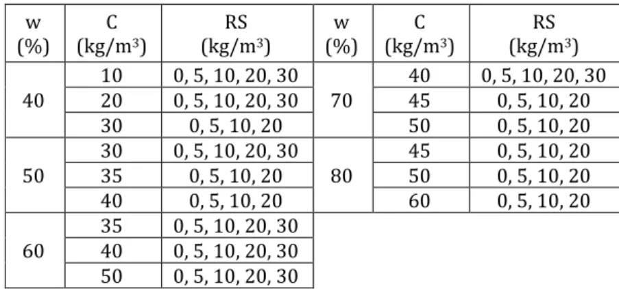
3-10 Testing conditions for develop empirical functions of RS fiber-cement-reinforced sludge . . . 62
3-12 Analysis of variance . . . 66
3-13 Model coefficients . . . 66
3-14 Testing conditions for in-soil curing condition . . . 69
3-15 Testing conditions for in-solution curing condition . . . 69
3-16 Soundness of specimens ranking . . . 75
3-17 Drying-wetting testing conditions for RS fiber-cement-reinforced sludge 75 3-18 Drying-wetting testing conditions for cemented-sludge . . . 75
4-1 ƞT/ ƞ15 coefficient . . . 86
4-2 Testing conditions for hydraulic conductivity tests . . . 87
4-3 Optimum conditions of RS fiber-cement-reinforced sludge . . . 88
4-4 Hydraulic conductivity of the modified-optimum conditions . . . 89
4-5 Testing conditions for unconfined compressive and durability in repeated drying-wetting tests . . . 90
4-6 Optimum conditions which satisfying three types of experiments . . . 92
4-7 Optimum conditions which satisfy unconfined compressive test and durability test . . . 92
4-8 Optimum conditions which satisfying unconfined compressive test and permeability test . . . 92
4-9 Testing conditions for submerged jet erosion tests . . . 102
List of Figures
1-1 Rice husk . . . 2
1-2 Rice straw and rice straw fiber . . . 2
1-3 Map of the Mekong Delta Transport Infrastructure Development Project (WB5) [9] . . . 3
1-4 Map of schematic presentation of urban and rural flood protection [3] . 4 1-5 Principle of Fiber-cement-stabilized soil method [10] . . . 7
1-6 Projects which applying Fiber-cement-stabilized soil method [10] . . . . 8
1-7 State-of-the-art of soil reinforcement technique [14] . . . 10
1-8 Rice straw reinforced soil gate in Vietnam [33] . . . 11
1-9 Coconut and coir fiber [36][37] . . . 12
1-10 Sisal plant and sisal fiber [38] . . . 13
1-11 Jute plant and its fiber [42] . . . 13
1-12 Flax plant and its fiber [43] . . . 14
1-13 Sugarcane and its bagasse fiber [44] . . . 14
2-1 Sketch of Rice husk-cement-reinforced soil method . . . 21
2-2 Water absorption of Japanese RH . . . 23
2-3 Japanese and Vietnamese RH . . . 23
2-4 Solidification processing of GEOSET cement . . . 24
2-5 Grain size distribution of actual sludge and imitated-sludge . . . 25
2-6 Mixing machine . . . 26
2-7 Yamato DKN 810 Convection Oven . . . 26
2-8 Metal mold and rammer . . . 26
2-9 Outline of unconfined compressive test . . . 27
2-11 Relationship between the failure strength, strain and rice husk content 31
2-12 Optimum amount of RH content of 40 % initial water content sludge . . 31
2-13 Optimum Japanese RH and cement content. . . 32
2-14 Effects of different type of sludge on compressive results . . . 33
2-15 Effects of RH type on compressive results . . . 34
2-16 Procedure of repeated drying-wetting test with compaction method . . 36
2-17 Mixing conditions changings for drying and wetting cyclic test . . . 37
2-18 Effects of initial curing time on specimen’s soundness . . . 39
2-19 Effects of initial curing time on failure strength and failure strain . . . . 39
2-20 Effects of initial water content on specimen’s soundness . . . 40
2-21 Effects of initial water content on failure strength and strain . . . 40
2-22 Effects of raw RH proportion on specimen’s soundness . . . 41
2-23 Effects of raw RH proportion on failure strength and strain . . . 41
2-24 Effects of adding another materials on specimen’s soundness . . . 42
2-25 Effects of another materials inclusion on failure strength and strain . . 43
3-1 Principles of rice straw-cement-reinforced sludge . . . 48
3-2 Procedure to make RS fibers . . . 49
3-3 Water absorption property of rice straw fiber . . . 49
3-4 Typical unconfined compressive results . . . 51
3-5 Unconfined compressive results for effects of RS fibers only . . . 52
3-6 Unconfined compressive results for effecting of RS’s length . . . 54
3-7 Stress-strain curves of unconfined compressive strength of different fibers modified-sludge . . . 56
3-8 Compressive results of different fiber composites . . . 57
3-9 Soil compaction curve . . . 58
3-10 Mass change through curing of rice straw fiber-cement-reinforced sludge . . . 58
3-11 Compaction curve of imitated sludge . . . 60
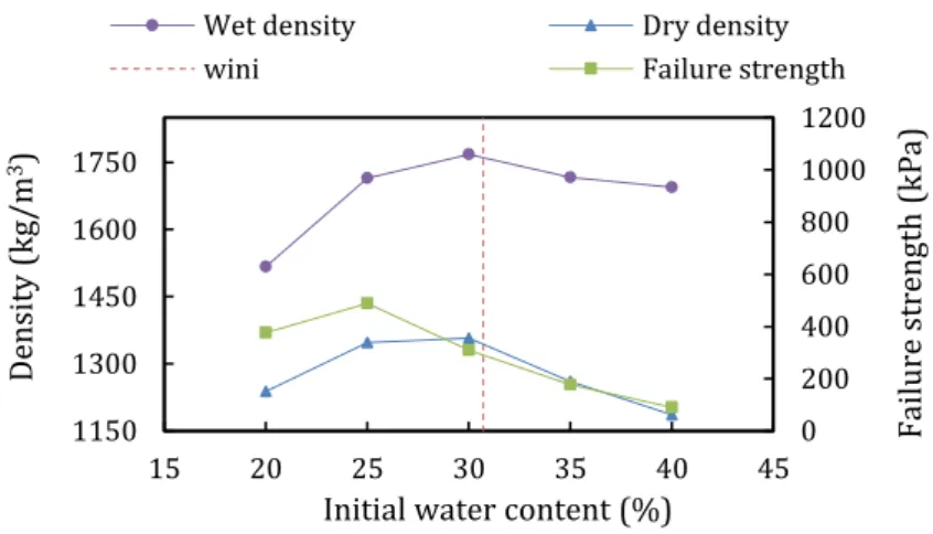
3-12 Correlation between dry density, wet density, and failure strength . . . 61
3-13 Correlation between permeability coefficient and initial water content . 61 3-14 Composite strength as function of fiber volume fraction [17] . . . 62
3-15 Compressive results for RS fiber-cement-reinforced sludge . . . 63
3-16 Kb values. Dashed-line is predicting value . . . 64
3-17 Optimum conditions of RS fiber-cement-reinforced sludge . . . 65
3-18 Correlation between observed and predicted data . . . 66
3-19 pH tester for soil . . . 68
3-20 Compressive results of long-term test with in-soil curing condition . . . 69
3-21 Compressive results by different curing condition . . . 70
3-22 SEM photos of normal RS fiber . . . 70
3-23 SEM photos of RS fiber in-soil curing condition . . . 71
3-24 SEM photos of RS fiber in-solution curing condition . . . 72
3-25 Compressive results by differences in pre-treatment RS fiber methods . 73 3-26 Procedure of repeated drying and wetting test with compaction method 74 3-27 Specimens’ soundness for RS fiber-cement-reinforced sludge . . . 75
3-28 Failure strength of RS fiber-cement-reinforced sludge . . . 76
3-29 Failure strain of RS fiber-cement-reinforced sludge . . . 76
3-30 Specimens after 10th cycles testing of RS fiber-cement-reinforced sludge 76 3-31 Specimens’ soundness of cement-reinforced sludge . . . 77
3-32 Specimens after testing of cement-reinforced sludge . . . 77
4-1 Sketch of water go through soil structure . . . 84
4-2 Paths of seepage through embankment dams . . . 84
4-3 Apparatus of permeability test . . . 84
4-4 Permeability testing procedure . . . 86
4-5 Permeability coefficient of rice straw fiber-cement-reinforced sludge . . 88
4-6 Permeability coefficient versus water content after curing . . . 88
4-7 Permeability coefficient of optimum conditions . . . 89
4-8 Unconfined compressive results of modified-optimum conditions . . . . 90
4-9 Soundness performance of modified-optimum conditions . . . 91
4-10 Failure strength and strain with cycle number of modified-optimum conditions . . . 91
4-11 Bank erosion cases in Mekong Delta . . . 94
4-13 Laboratory submerged jet apparatus . . . 97
4-14 Schematic of submerged jet apparatus . . . 97
4-15 Schematic of circular submerged jet with parameters and stress distribution [31] . . . 98
4-16 Graphical view of estimation of equilibrium depth and dimensionless time function [31] . . . 101
4-17 Plots of scour depths versus time for W40C0RS15 . . . 102
4-18 Graphical view of estimation of equilibrium depth of W40C0RS15 #1 . 103 4-19 Graphical view of dimensionless scour function optimization of W40C0RS15 #1 . . . 103
4-20 Scour development of W40% conditions . . . 103
4-21 Scour development of W60% conditions . . . 104
4-22 Scour development of W80% conditions-RS fibers . . . 104
4-23 Scour development of W80% conditions -paper fragment . . . 105
4-24 Comparisons of scour developments at W80%-modified-sludge with RS fibers vs paper fragment inclusions . . . 105
4-25 Soil specimens after JET tests for the conditions of W40% . . . 108
4-26 Soil specimens after JET tests for the conditions of W60% . . . 109
4-27 Soil specimens after JET tests for the conditions of W80%-RS fibers . . 110
4-28 Soil specimens after JET tests for comparison between conditions of W80%-RS fibers and W80%-paper fragment . . . 111
4-29 Critical shear stress and erodibility coefficient results of tested conditions . . . 113
4-30 Classifications of modified-sludge at W40% . . . 114
4-31 Classifications of modified-sludge at W60% . . . 114
4-32 Classifications of modified-sludge at W80% with RS fibers inclusion . . 115
4-33 Classifications of modified-sludge at W80% with paper fragment inclusion . . . 115
4-34 Correlation between τc and kd for modified-sludge with RS fibers inclusion and comparison to previously proposed relationships by Hanson and Simon [52] (dashed line) and Simon et al. [53] (dotted line) 116 5-1 Application for modified-sludge with RH by compaction method . . . . 125
1.1 Problem definition
1.1.1 The state-of-the-art of sludge and rice by-products in
Vietnamese Mekong delta
Vietnamese Mekong delta (VMD hereafter) is one of the largest deltas in the world in terms of drainage basin size, freshwater discharge, and sediment flux annually [1], [2]. It can be classified into flood plain and strand plain, with mangrove swamp along its shore. In addition, the delta is very flat with the average elevation is about 0.8 m above the mean sea level. It has two distinctly seasons, one is monsoon season and the other one is drought season. The climate is highly appropriate for rice cultivation. It is mainly covered by fertile alluvial plain and 65% of its land is used for agriculture and fishery [3]. The area remains active as the granary of Vietnam due to its nutrient-rich soils and dense canals.
As results, agricultural by-products, rice husk and rice straw, are becoming complex problems. It is estimated that Vietnam produces more than 30 million tons of rice by-products every year [4]. While rice straw is mainly left and directly burning on
Chapter 1
Introduction
the fields after harvesting, rice husk is produced in large quantities in hundreds of thousands of rice mills all over the country. Annually in VMD, the rice husk is discharged more than 4 million tons [4]. There are several common methods to use the rice husk in the delta such as for cooking (15%), for brick kiln (40-45%), briquette (10%), left over (20-25%) [5]. Figure 1-1 shows a typical photo of rice husk.
Figure 1-1 Rice husk
On the other hand, the estimated quantity of rice straw is approximately of 26.2 million tons [6]. In the delta, there are six common types of applications for the straw such as burning, burying, mushroom cultivation, breeding, sale, and giving to neighbors, in which the mostly types of treatment and management is burning with more than 80% amount of rice straw is burned directly on the fields. The burning will be continue as a habit of farmers in the coming years [6]. The original rice straw is too long and thick for using as fiber material. Therefore, the rice straw has to pre-treat before applying it to modify the sludge. Figure 1-2 shows photos of original rice straw and its fiber.
Figure 1-2 Rice straw and rice straw fibers
Another important feature in this area is the high density of waterways. It is approximately 0.68 km/km2. Due to flat topography and low flow velocity, annually the
amount of deposited sediment on the river’s bed is approximately 160-165 million tons/year [7]. Moreover, the waterway transportations in the delta always represents 60-70% of total transport volume. From 2012, Vietnamese government has developed the Mekong Delta Transport Infrastructure Development Project, also known as WB5, by supporting of World Bank for roads and highways, ports, waterways, and shipping systems. The general objectives of the project are to support sustainable economic growth and to include development in the Mekong Delta Region by increasing the efficiency of transport infrastructure in the Delta in an integrated and safe manner by means of multi-modal transport [8]. The component – National Waterway Corridor Improvements, aims to improve the standard and connectivity of keys waterway freight corridors include dredging 401 km to the required widths and depths, bank protection in selected area, a ship lock, bridge improvements [8]. Figure 1-3 shows a map of the Mekong Delta Transport Infrastructure Development Project [9].
Figure 1-3 Map of the Mekong Delta Transport Infrastructure Development Project (WB5) [9]
Furthermore, the delta is severely being affected by climate change, global warming, and upstream development such as building of the upstream hydropower. Water flow and flood pattern will be changed significantly when hydropower dams are in full operation especially in monsoon season and this also will change salinity intrusion in dry season. In Vietnam, climate change has been extensively studied at the regional, and national scales. From 2008, Vietnamese government has formulated a master plan and national target program to respond to the climate change and
sea-level rise with the aim of creating irrigation systems, serving agricultural production in the new situation, contribute to social and economic development, eco-environmental protection and sustainable development. In additions, a master plan of water resources and irrigation systems for Mekong Delta in climate changes and sea level rise conditions with period from 2012 to 2020 and the orientation until 2050 (decision 1397, 2012) is issued. Contents of the decision are follows:
Improvement of the irrigation system, the water supply, drainage, flooding control, salinity control.
Dredge more canals to improve the flooding discharge capacity in monsoon season and freshwater holding capacity in dry season. Until now, many dredging canal and river projects are undertaken. As a result of these projects, a huge amount of sludge has been discharged.
Complete system of sea dykes, river dykes (full-dyke and semi-dyke main rivers and border) regulating sewerage system to prevent saltwater, to keep freshwater. As a result of this target, a huge amount of soil need for dyke constructions.
Figure 1-4 shows a map of schematic presentation of urban and rural flood protection in the Mekong Delta [3].
Figure 1-4 Map of schematic presentation of urban and rural flood protection [3]
In general sludge, rice husk, and rice straw are significantly affecting the environmental quality and landscape. It is necessary to recycle these materials into a new ground-material as a sustainable strategy for our environment. Currently, the
recycling rate of the sludge is extremely low because of its high water content properties. Most of them is intermediately transported to landfill followed by dehydration treatment method. However, the lack of final disposal sites, and high transportation costs are the posing serious problems. Therefore, the burden of illegal dumping seems never to end [10]. On the order hand, Vietnamese government is building many dykes. In order to make dyke, large amount of soil is necessary. If the dredging sludge could be used for constructing the dyke, it will be very useful. However, the dredging sludge cannot directly be used because it contains a large amount of water. Therefore, a method to modify the sludge to become a suitable material for building dyke is raised.
Sludge is like soil with high water content. Depends on excavation methods and post-excavation time, water content of sludge can be reach to several hundred percentage. At high water content, the sludge looks like “fluid”. Its bearing capacity and shear strength are very low. Therefore, to increase the strength as well as bearing capacity of sludge, the primary purpose is reduce the water content. There are several methods to improve the mechanical characteristics of dredging sludge. However, as discussed before, the “Fiber-cement-stabilized soil method” seems to be the most suitable method to deal with the dredging sludge.
1.1.2 Fiber-cement-stabilized soil method
The stabilization of soils has been performed for millennia. For instance, the Mesopotamians and Romans separately discovered that it was possible to improve the ability of pathways to carry traffic by mixing the weak soils with a stabilizing agent like pulverized limestone or calcium. This was the first chemical stabilization of weak soils to improve their load carrying [11].
On the other hands, the concept of fiber reinforced soil has developed since ancient times. Plant roots were presented as a natural means of incorporating to improve the properties of weak soil. The main role of short discrete fibers in the mix is to control crack opening through shrinkage happen by hardening procedure of cement. Fibers reduce the brittle characteristics of build materials. The fibers improved the strength of the soils and stabilized the natural slope. Fibers have been used to strengthen brittle building materials, for instance, straw, horse-hair, and other
vegetable fibers were mixed with clay to form bricks and floors [12]. Ancient civilizations used straw and hay to reinforce mud blocks in order to make reinforced building materials. There are several examples of reinforcing the soil like Great Wall of China (earliest example of reinforced earth using branches of trees as tensile elements), ziggurats of Babylon (woven mats of reed were used), etc [13].
Since 1966, Vidal demonstrated the improving of shear strength of the soil by adding reinforcing elements. After Vidal’s study was introduced, there are more than 4000 structures have been constructed around 37 countries by applying the concept and principle of soil reinforcement [14]. Recently, the applications of using randomly discrete fiber on geotechnical engineering, not only in scientific research environment, but also at executive real field, have recently attracted increasing attention.
The natural fibers reinforced soil' concept has originally developed since ancient times. However, randomly discrete natural fiber reinforced soil has recently attracted increasing attention for the second time. Therefore, they are still a relatively new technique in geotechnical projects.
The “Fiber-cement-stabilized soil method” is a recycling method for high water content mud by adding paper debris and cement. The method has developed based on dealing with the difficulty of directly recycle construction sludge and water purification sludge. The reason for the difficulty is because the water content of these sludge is extremely high. Therefore, they have been discarded in the final disposal sites. However, the remaining capacity of the final disposal sites is decreasing and is not enough. Furthermore, since the transportation cost of these sludge is expensive, they are often thrown away illegally on the way to the final disposal sites. In result, the recycling rate of the construction sludge is extremely low.
The method has evaluated on both for academic and real cases in Japan. By the end of March, 2014, it had been applied in 360 cases with total of 530,000 m3 in Japan
[10]. The sludge after treated by Fiber-cement-stabilized soil method can be used as backfill materials or embankment’s materials to build road or river banks. The principle of this method is described as follows [15]–[22]:
As shown in Figure 1-5 (a), the sludge particles are free to move in the water because it is in state of low yield stress. In other words, the sludge behaves as
In Figure 1-5 (b), if materials such as waste paper or textiles with high water absorption are added, the free water around sludge particles is absorbed by the fibrous materials. And then, the superficial water content of the sludge decreases.
In Figure 1-5 (c), binder materials such as cement is added. Binder’s hydrate reaction is occurred. Cross-linking is generated to bind soil particles and fiber material. As results, strength of the modified-sludge is increased.
In Figure 1-5 (d), the modified-sludge is cured at appropriately conditions such as time and temperature. Finally, the modified-sludge can be applied for recycle.
Figure 1-5 Principle of Fiber-cement-stabilized soil method [10]
The modified-sludge by apply the method has some advantages, such as high failure strength, high failure strain, high durability for drying and wetting, high durability for freezing and thawing, this method has more than 200 actual achievements. Furthermore, it was confirmed that the modified-sludge has high dynamic strength and high resistance for the earthquake. Figure 1-6 show photos of some projects which applying Fiber-cement-stabilized soil method in Japan.
Construction of Sewerage Pipe in Obanazawa City in Yamagata Prefecture
Construction of River Bank in Hamao Area in Fukushima Prefecture
Construction of Public Utility Conduit in Sendai City in Miyagi Prefecture
Figure 1-6 Projects which applying Fiber-cement-stabilized soil method [10]
Therefore, the Fiber-cement-stabilized soil method is considered as a good method to recycle the dredged-sludge in Mekong delta. However, it is very difficult to collect a large amount of paper debris in the delta. Moreover, the price of paper debris is getting higher, nowadays. Besides that, as mentioned before, this area has a large amount of rice husk and rice straw (agriculture wastes). If the rice husk and rice straw
1.2 Aims of the study
In general, the aims of the study were to apply the “Fiber-cement-stabilized soil method” to recycle the dredging sludge in Vietnamese Mekong delta by using local natural fiber materials rice husk and rice straw. In term of mechanical characteristics, the modified-sludge was studied on several features as list as:
Investigate the effects of adding rice husk, rice straw, and cement on unconfined compressive strength of sludge.
Study the durability modified-sludge in term of repeated drying-wetting and long-term.
Investigate the effects of adding rice straw fibers on permeability of modified-sludge.
Study the influence of rice straw fibers and cement inclusion on erosion characteristics in conditions of submerged jets.
Develop empirical equations, and statistical functions.
1.3 Literature review
Soil often combines with four basis types: gravel, sand, silt, and clay. In case of sludge, it can be regarded as a combination of clay and silt [14]. Sludge has low shear strength, bearing capacity, permeability coefficient, and so on. For improving these sludge’s characteristics, reinforcement is needed. Soil reinforcement is defined as a technique to improve the mechanical characteristics of soil such as shear strength, compressibility, density, hydraulic conductivity, and bearing capacity [23].
Reinforced soil techniques are effective and reliable techniques. The classification of soil reinforcement technique can be undertaken into a number of categories. Figure 1-7 shows the state-of-the-art of soil reinforcement techniques. Some of the listed techniques may have disadvantages of being ineffective and/or expensive and advantages effects. So, new methods are still being researched [14]. It is very important to know what the exactly targets to improve soft soil because for the same soft soil there are several techniques can be applied for. Therefore, the section
focuses some soil reinforcement methods that related to the research such as lime adding, cemented-soil, randomly fibers mixing, and fiber inclusion cemented-soil.
Soil reinforcement
techniques
2-Physical: vibration, thermo-electrical, freeze and thaw 1-Mechanical: compaction
5-Combination
4-Fibrous inclusion Geosynthetic fibers 3-Chemical Randomly discrete fibers Natural fibers Man-made fibers Mineral fibers Geogrid Geotextile Geocomposite Geonet Geocell
Cementing material: cement, lime, rice husk ash, fly ash, Enzymes: PZ-22X,
Polymeric resins: polyvinyl acrylic, polyvinyl acetate,...
Figure 1-7 State-of-the-art of soil reinforcement technique [14]
Lime stabilization consists of mixing lime with soil to increase bearing capacity. It is the oldest traditional chemical stabilizer used for soft soil improvement. The increase in strength occurs because the calcium cations in the hydrated lime replace the cations present in the clay mineral. Advantages of this method are that it is good performance in road construction, easy availability, quick reaction, improve soil compressibility, and low cost [24],[25]. However, it is toxic for plants and human health [26]. The process of lime-treated is responsible for a considerable percentage of carbon dioxide emission in addition to high energy consumption.
Cement-treated soil has been used widely in soil improvement due to its economy, availability and feasibility [27]. Soft soil has high water content and when cement added it definitely decreases its liquid limit and increase its strength as it ages while calcium hydroxide contributes to the pozzolanic reaction as in the case of lime stabilization [26]. It has some disadvantages, especially at high cement content, to resist to dynamic loads and durability [27]. Cement solidified materials subjected to repeat wet and dry cycling tests [15]. Due to the cement’s ability of using alone to bring the requested stabilizing action, it can be considered as primary stabilizing agent or hydraulic binder. The cement-stabilized soil contains enough cement to interact with
the fine fraction and to deprive the fines of their water affinity, but not enough to bond all of the soil particles into a coherent mass [28].
Discrete fiber-stabilized soils have generally shown significantly improvements not only soil shear strength, also bearing capacity. The failure mechanism of a fiber-reinforced soil depends on the acting average effective stress [29]. The fiber inclusion indicated that the fiber content, orientation of fibers with respect to the shear surface, and the elastic modulus of the fibers affect the contribution of the reinforcement to the shear strength. The fiber reinforcement increases the peak strength, decreases stiffness, and changes the cemented soil’s brittle behavior to a more ductile one [30]. With the fiber-reinforced, it showed that it has higher durability for drying and wetting cycles than cemented-soil only [15]. Compared with oriented or aligned reinforced soil, fiber reinforced soils with random distribution of fibers exhibit some advantages. One of the main advantages of using randomly distributed fibers is the maintenance of strength isotropy and the absence of potential planes of weakness that can develop in soils with oriented reinforcement [31]. The mainly effective of the fiber-stabilized soil is the significant increase of shear strength. Therefore, the implementation of the fiber-reinforcement improves the soil bearing capacity because of the direct relationship of soil bearing capacity and shear strength. The bearing capacity is used for foundation designing. The relationship between shear strength and bearing capacity and the failure mechanism had developed by Terzaghi in 1943 [32].
Natural fibers have been used for a long time (from ancient time to modern time) in many developing countries because their availability and low cost. Figure 1-8 shows a structure that use natural fiber reinforced soil.
Nowadays, the sustainable development is a modern tendency in the world. There is a need to develop friendly environmental building materials. Therefore, the term “eco-composite” shows the importance role of natural fibers in the modern industry [34]. In followings, some features of applying natural fibers in soil reinforced will be discussed. There are many factors that affect to the performance of fiber in soil. For example, what part of the plant the fiber came from, the age of the plant when the fiber was harvested, how the fiber was isolated, and so on [35].
Previous researchers mentioned that the optimum water content of modified-soil increased with increasing the percentage of coir and the maximum density of modified-soil decreased with adding of coir fiber. The compressive strength and tensile strength increased with an addition in the percentage of coir [36]. Natural fibers consist of lignin, tannin, cellulose, pectin and other water soluble substances. High lignin content contributes to longer service life. In wet condition, coir retains much of its tensile strength. Coir retains 80% of its tensile strength after 6 months of embedment in clay [37]. Figure 1-9 shows a cross section of coconut and coir fiber.
Cross section of coconut Coir fiber
Figure 1-9 Coconut and coir fiber [36] [37]
Also, the inclusion of sisal reduced the dry density of the soil due to a low specific gravity and unit weight of sisal fiber. The increase in the fiber length and fiber content reduces the dry density of the soil and increased tensile behavior of unbaked soil as a building material. The increasing of fiber length up to 20 mm increased the shear strength of modified-soil. However, beyond 20 mm in length, the shear strength decreased with increasing fiber length. The increasing of fiber content also improves the shear strength. However beyond 0.75% fiber content, the shear strength reduces
contents reduce the interlock of soil particles and therefore, fiber-soil particles do not act as a single coherent mass [38]–[41]. Figure 1-10 shows sisal plant and its fiber.
Figure 1-10 Sisal plant and sisal fiber [38]
Proctor Compaction tests and California Bearing Ratio tests have been carried out with jute fibers to investigate the effect of the jute reinforcement on the maximum dry density (MDD) and optimum moisture content (OMC) and the effect of the jute reinforcement on California bearing ratio. Bitumen was used for coating fibers to protect them from microbial attack and degradation. The results indicated that inclusion of jute fiber reduced the MDD and increased the OMC. However, diameter of the fiber did not have much effect on the maximum dry density and optimum moisture content. Maximum CBR value is observed with 10 mm long and 0.8 % jute fiber content, an increase of more than 2.5 times of the plain soil CBR value [42]. Figure 1-11 shows jute plant and cut jute fiber.
Figure 1-11 Jute plant and its fiber [42]
Flax plant fiber was coated by an enamel paint coating to improve the interfacial bond strength [43]. The experimental results showed that the adding of fiber to cemented-soil could significantly improve the ductility of the composite. Figure 1-12 shows the flax plant and flax fiber.
Figure 1-12 Flax plant and its fiber [43]
Soil blocks reinforced with sugarcane bagasse fibers and conducted on density, water absorption, compressive strength, splitting tensile strength and erosion tests [44]. The results indicated that with an optimum amount of sugarcane bagasse fibers, the modified-soil achieved better strength, and better resistance against erosion. Figure 1-13 shows the sugarcane and sugarcane bagasse fiber.
Figure 1-13 Sugarcane and its bagasse fiber [44]
In this research, the applied fibers are rice husk and rice straw. Until now, there are several researches have being studied about the including of rice husk and rice straw on soil composite. A study on effect of rice husk on soil samples showed that increasing of rice husk content could increase the soil’s strength [45]. The strength reached a maximum value at the optimum rice husk content. It can be applied for a temporary slope stabilization. In short term, it can stabilize the soil when the seeds are planted. In long term, when the husk degrades it act as manure for the growth of plants and also makes the soil airy which result in less runoff during heavy rains [45]. Moreover, the inclusion of wheat straw fibers increased the shear strength of unreinforced soil for all lengths [28]. The fibers were more severely attacked by alkaline medium and water when subjected to alternate wetting and drying type
1.4 Structure of the dissertation
The dissertation consists of five chapters.
Chapter 1 is an introductory chapter outlining the problem statement, the objectives of the research work, and the scope of the study. Furthermore, literature review and theoretical principles of some of the main articles, studies and researches that were needed for this research are mentioned in this chapter.
Chapter 2 discusses the effects of rice husk, and cement inclusion on unconfined compressive strength, and repeated drying-wetting durability of modified-sludge. Empirical equations to predict the optimum additive amount of materials (rice husk and cement) were obtained.
Chapter 3 shows a procedure to make rice straw fiber from original rice straw was produced. The effects of fiber’s length, comparison between several types of fibers, evaluation of optimum making condition on compressive strength of rice straw fiber-cement-reinforced sludge were presented. Empirical optimum equations were proposed from experimental data. Also, durability of the rice straw fiber-cement-soil composites on long-term condition and in cyclic drying and wetting condition were conducted.
Chapter 4 shows the experimental results of studies on permeability and on erosion characteristics of rice straw-cement-reinforced sludge by submerged jet. Also, empirical equations were developed.
Chapter 5 is conclusions. Summaries and recommendations are presented. Also future study was presented. Furthermore, some implementations were proposed at the end of this chapter.
References
[1] T. K. A. Ta and T. Nakamura, “Sediment facies and Late Holocene progradation of the Mekong River Delta in Bentre Province, southern Vietnam: an example of evolution from a tide-dominated to a tide- and wave-dominated delta,” Sediment.
Geol., vol. 152, pp. 313–325, 2002.
[2] J. D. Milliman and J. P. M. Syvitski, “Geomorphic/Tectonic Control of Sediment Discharge to the Ocean: The Importance of Small Mountainous Rivers,” J. Geol., vol. 100, pp. 525–544, 1992.
[3] A.F.Timan, “Mekong Delta Plan. Long-term vision and strategy for a safe, prosperous and sustainable delta,” 2013.
[4] “San Xuat Nhiet Dien Tu Trau.” [Online]. Available:
http://www.xaydung.gov.vn/vi/web/guest/trang-chi-tiet/-/tin-chi-tiet/Z2jG/86/39336/san-xuat-nhiet-dien-tu-trau.html. [Accessed: 19-Jun-2019].
[5] S. N. D. O. Vietnam, “Biomass opportunities Viet Nam,” NL Agency NL Energy and Climate Change, Netherlands, 2012.
[6] S. N. Tran and K. Ingvorsen, “To quantify the seasonal rice straw and its use in different provinces in the Vietnamese Mekong Delta,” Can Tho Univ. J. Sci., vol. 32, pp. 87–93, 2014.
[7] T. Konishi, “Climate Change on the Vietnam, Mekong Delta. Expected impacts and adaptations,” 2002.
[8] TheWorldBank, “Mekong Delta Transport Infrastructure Development Project,” 2012.
[9] G. Pichel and R. H. DHV, “Mekong Delta Transport Infrastructure Development Project,” 2013.
[10] H. Takahashi, Topical Themes in Energy and Resources. Japan: Springer, 2014. [11] T. E. Kowalski and D. W. Starry, “Modern soil stabilization techniques,” Conf.
Transp. Assoc. Canada, p. 16, 2007.
years of development in building and civil engineering,” Compos. Struct., vol. 86, no. 1, pp. 3–9, 2008.
[13] J. Rao, “Jute Geotextile for improving the performance of Highway Embankment on soft Marine Soil,” in Proc. Nat.Sem, on Jute based Geotextiles, 1996.
[14] S. M. Hejazi, M. Sheikhzadeh, S. M. Abtahi, and A. Zadhoush, “A simple review of soil reinforcement by using natural and synthetic fibers,” Constr. Build. Mater., vol. 30, pp. 100–116, 2012.
[15] H. Takahashi and T. Satomi, “Study on Durability for Drying and Wetting of Cover Soil for Radiation-Contaminated Soil Made of Tsunami Sludge,” J. JSEM, vol. 14, pp. s309–s313, 2014.
[16] T. Satomi and H. Takahashi, “Experimental evaluation of optimum making conditions for fiber-cement-stabilized soil made of tsunami sludge,” J. Japanese
Soc. Exp. Mech., vol. 15, no. 3, pp. 225–230, 2015.
[17] M. Mori and H. Takahashi, “A proposal of new recycling system for high-water content muds by using paper debris and polymer and strength property of recycled soils,” J. MMIJ, vol. 119, pp. 155–160, 2003.
[18] M. Mori, H. Takahashi, and K. Kumakura, “An Experimental Study on Strength of Fiber-Cement-Stabilized Mud by use of Paper Sludge and Durability for Drying and Wetting Tests,” J. MMIJ, vol. 122, pp. 353–361, 2006.
[19] P. T. Chien, T. Satomi, and H. Takahashi, “Study on permeability characteristics of rice straw fiber-cement-reinforced sludge,” in Proceedings of the 2nd joint
seminar on landslide, flood disasters and the environmental issues, 2018.
[20] H. Takahashi and M. Mori, “Creation of artificial ground by recycling tsunami sludge,” in Proceedings of the 6th Symposium on Sediment-Related Disasters, 2012. [21] P. T. Chien, T. Satomi, and H. Takahashi, “Study on sludge recycling with
compaction type and placing type by rice husk-cement-stabilized soil method,”
Adv. Exp. Mech., vol. 2, pp. 159–167, 2017.
[22] T. Satomi and H. Takahashi, “Evaluation of Failure Strength Property and Permeability of Fiber-Cement-Stabilized Soil Made of Tsunami Sludge,” J. JSEM, vol. 14, pp. s303–s308, 2014.
[23] S. Kazemian, B. B. K. Huat, A. Prasad, and M. Barghchi, “A Review of Stabilization of Soft Soils,” Aust. J. Basic Appl. Sci., vol. 4, no. 12, pp. 5862–5868, 2010.
[24] D. H. Gray and H. Ohashi, “Mechanics of Fiber Reinforcement in Sand,” J. Geotech.
Eng., vol. 109, no. 3, pp. 335–353, 1983.
[25] N. Consoli and L. A. Ulbrich, “Influence of Fiber and Cement Addition on Behavior of Sandy Soil,” J. Geotech. Geoenvironmental Eng., vol. 124, no. 12, pp. 1211–1214, 1998.
[26] J. D. Hussin, The Foundation Engineering Handbook. Taylor & Francis Group, 2006.
[27] M. Maher and Y. Ho, “Behavior of Fiber-Reinforced Cemented Sand Under Static and Cyclic Loads,” Geotech. Test. J., vol. 16, pp. 330–338, 1993.
[28] J. Qu and J. Sun, “Strength Behavior of Shanghai Clayey Soil Reinforced with Wheat Straw Fibers,” Geotech Geol Eng, vol. 21, pp. 511–518, 2013.
[29] S. I. Ali and S. Bhattacharjee, “Ground Improvement Techniques: Lime Stabilization,” Publ. Int. J. Adv. Res. Civil,Structural,Environmental Infrastruct. Eng.
Dev., vol. 1, no. 3, pp. 123–129, 2014.
[30] A. A. Abiodun and Z. Nalbantoglu, “Lime pile techniques for the improvement of clay soils,” Can. Geotech. J., vol. 52, pp. 760–768, 2015.
[31] I. T. Jawad and T. Khan, “Soil Stabilization Using Lime: Advantages, Disadvantages and Proposing a Potential Alternative,” Res. J. Appl. Sci. Eng.
Technol., vol. 8, no. 4, pp. 510–520, 2014.
[32] M. Kitazume and M. Terashi, The Deep Mixing Method. CRC Press/Balkema, 2013. [33] “NHADANVIETNAM: NHÀ TRANH VÁCH ĐẤT.” [Online]. Available:
http://nhadanvietnam.blogspot.com/2012/10/nha-tranh-vach-at.html. [Accessed: 19-Jun-2019].
[34] H. Ismail and F. L. Chung, “The Effect of Partial Replacement of Silica by White Rice Husk Ash in Natural Rubber Composites,” Int. J. Polym. Mater. Polym.
Biomater., vol. 43, no. 3–4, pp. 301–312, 1999.
2000.
[36] A. U. R. Shankar and K. S. Raghavan, “Coir stabilised lateritic soil for pavements,” in Indian Geotechnical Conference, vol. 1, pp. 436–439, 2004.
[37] G. L. S. Babu and A. K. Vasudevan, “Strength and Stiffness Response of Coir Fiber-Reinforced Tropical Soil,” J. Mater. Civ. Eng., vol. 20, no. 9, pp. 571–577, 2008. [38] J. Prabakar and R. S. Sridhar, “Effect of random inclusion of sisal fibre on strength
behaviour of soil,” Constr. Build. Mater., vol. 16, no. 2, pp. 123–131, 2002.
[39] R. Mattone, “Sisal fibre reinforced soil with cement or cactus pulp in bahareque technique,” Cem. Concr. Compos., vol. 27, no. 5, pp. 611–616, 2005.
[40] K. J. Giridhar and R. R. M. V. G. K., “Moisture absoprtion charateristic of natural fiber composites,” Joumal Reinf. Plast. Compos., vol. 5, pp. 141–150, 1986.
[41] Z. Jamellodin, Z. A. Talib, R. Kolop, and N. M. Noor, “The effect of oil palm fibre on strength behavior of soil,” in Proceedings of the 3rd SANREM, 2010.
[42] P. Aggarwal and B. Sharma, “Application of jute fiber in the improvement of subgrade characteristics,” in Proc. of Int. Conf. on Advances in Civil Engineering, 2010.
[43] M. Segetin, K. Jayaraman, and X. Xu, “Harakeke reinforcement of soil–cement building materials: Manufacturability and properties,” Build. Environ., vol. 42, no. 8, pp. 3066–3079, 2007.
[44] H. Danso, D. B. Martinson, M. Ali, and J. B. Williams, “Effect of sugarcane bagasse fibre on the strength properties of soil blocks,” First International Conference on
Bio-based Building Materials. Clermont-Ferrand, France, pp. 1–7, 2015.
[45] A. Chacko and M. J. Poweth, “Effect of Rice Husk on Soil Properties,” Int. J. Eng.
Res. Dev., vol. 9, no. 11, pp. 44–49, 2014.
[46] P. G. Greeshma and M. Joseph, “Rice Straw Reinforcement for Improvement in Kuttanad Clay,” in Proceedings of Indian Geotechnical Conference, 2011.
[47] M. Bouhicha, F. Aouissi, and S. Kenai, “Performance of composite soil reinforced with barley straw,” Cem. Concr. Compos., vol. 27, no. 5, pp. 617–621, 2005.
2.1 Introduction
In this chapter, the sludge is reinforced by adding rice husk and cement. It is named as rice husk-cement-reinforced sludge. As follows, principles of modified-sludge are described. Figure 2-1 shows a sketch of the material.
Figure 2-1 (a) simulates a natural sludge sample. Because of the high moisture property and low yield stress, sludge particles can freely move as a fluid [1]. Rice husk is added to absorb free water, controls shrinkage, and provide
flexibility. The water content decreases as shown in Figure 2-1 (b).
Cement is added to reduce the plasticity and water-holding capacity of the sludge as shown in Figure 2-1 (c). Hydrate reactions generates and the sludge’s strength increases.
The modified-sludge was investigated on unconfined compressive strength and durability in repeated drying-wetting. On the study, conventional compaction method was applied for specimens making.
Chapter 2
Strength and durability of rice
husk-cement-reinforced sludge
Figure 2-1 Sketch of Rice husk-cement-reinforced soil method
Soil compaction is defined as the method of mechanically increasing the density of soil by packing the soil particles closer together causing a reduction in the volume of air. Soil water acts as a lubricant increasing compaction when a load is imposed on the soil. And it is usually no change in the processing. Purposeful compaction is intended to improve the strength and stiffness, and to decrease voids ratio and so permeability of soil. In the construction of embankments, earth dams, and many other engineering structures, compaction method is mostly applied [2][3].
2.2 Materials
Three types of materials were used: imitation sludge, cement, and raw rice husk.
2.2.1 Rice husk
Rice husk (RH) is the outer covering of the rice grain and obtained during the milling process. RH plays a role as a fiber material in the rice husk-cement-reinforced sludge. Generally, suitable natural fiber is selected based on the following parameters:
Fiber must not be hazarded to its surrounding environment. It must be easily obtainable and inexpensive.
Its preparing method should be simple.
RH was selected as one of suitable fiber materials due to some advantages compared to other fiber materials. RH is a majority by-product of the rice milling industry and one of the most commonly available lignocellulosic materials [4]. It is easy to obtain and its price is also cheap. Another advantage is that it can be directly apply into sludge without any preparation compared to rice straw that need trimming pre-preparation. RH has resistance against corrosion and deterioration in the soil in a certain period of time even though it is not specially processed. The physical and chemical properties of RH are found to vary from sample to sample due to type of paddy, crop year, climatic and geographical conditions. RH contains 75-90% organic matter such as cellulose, lignin ect., and rest mineral components such as silica, alkalis and trace elements [5].
Two types of RH, Japanese and Vietnamese RH, were applied. Japanese RH is obtained in Miyagi prefecture, Japan and Vietnamese RH is collected in Tien Giang prefecture, Vietnam. The typical properties of RH are shown in Table 2-1, Table 2-2, and Figure 2-2.
Table 2-1 RH’s properties
Properties Values Note
Hardness 5-6 (Mohr’s scale) [6]
Bulk density 81-107kg/m3 Moisture 10-12% Vietnamese (length) 7.6-12mm Vietnamese (width) 0.8-2.5mm Japanese (length) 6.2-8.1mm Japanese (width) 1.25-3.25mm
Table 2-2 Dimensions of Japanese and Vietnamese RH
Values Length (mm) Width (mm)
Vietnamese Japanese Vietnamese Japanese
Mean 9.33 7.14 1.60 2.05
Standard Deviation 0.69 0.42 0.33 0.41
Minimum 7.60 6.20 0.80 1.25
Figure 2-2 Water absorption of Japanese RH
Table 2-2 show that Vietnamese RH is about 30% longer and 22% thinner than Japanese RH. Previous studies indicated that an increasing of fiber’s length increased the peak strength of modified-soil until a certain limitation of length [7][8][9]. Therefore, it can consider that the length of RH plays an important role on behavior of rice husk-cement-reinforced sludge. As results, Vietnamese RH can improve the strength of modified-sludge better than Japanese RH due to its longer length.
When a certain pozzolanic materials containing amorphous silica are added during the hydration of Portland cement, its reaction with lime produces additional amount of calcium silicate hydrate (C-S-H) [10].
Figure 2-3 shows photos of Vietnamese and Japanese RH. Hypothetically, the high silica content of RHs could contribute to the pozzolanic reaction of cement during hydration and enhance the bonding strength of the soil mass. A work on mortar admixed with RHs and cement observed that the pozzolanic role of RH was due to the existence of silica in amorphous and fine grained quartz in the mixture. Pozzolanic effect exhibits cementitious properties that increase the rate at which the material gains strength [11]. The pozzolanic action on the surface of the husk could be promoted by the amorphous silica which is concentrated on the interior and exterior surfaces of the uncalcinated husk. [11]. Table 2-3 shows a micro analysis of the surface of RH.
0 25 50 75 100 125 0 10 20 30 60 120 360 W ate r con te nt (%) Time (minute) Japanese RH Vietnamese RH
Table 2-3 Micro analysis of the surface of RH [11]
Element External surface % Interior Internal surface
(by weight) (atomic) % (by weight) % (atomic) % (by weight) % (atomic) %
C 6.91 11.11 62.54 69.54 30.20 40.93
O 47.93 57.84 35.19 29.38 42.53 43.27
Si 45.16 31.05 2.27 1.08 27.27 15.80
Total 100.00 100.00 100.00 100.00 100.00 100.00
The chemical reaction between silica from RH with cement and sludge is represented by Equation 2-1 and 2-2 [12]. Like a reaction between a week acid and a strong base, the strong base eventually dissolves the silica within the RH and clay soil to form hydrous silica. The secondary silicate is gradually generated from the react of the hydrous silica and the calcium ions known as insoluble and cementitious materials. That means the solution of silica actually generates additional bonding forces in the cemented soil. Upon curing, the secondary cementitous products will harden and provide secondary bondage strength to the stabilized soil. This reaction is referred to as secondary pozzolanic reaction.
+
-2
Ca(OH) Ca + 2(OH) (2-1)
+
-2 2 2
Ca + 2(OH) + SiO CaO.SiO .H O (2-2)
2.2.2 Cement
The cement used in this research is GEOSET-200 which is produced by Taiheiyo Cement Corporation, Japan. It is a cement-based solidifying agent that reacts quickly when it is mixed with soil. When mixed with soil, it rapidly forms needle-shaped ettringite. The resulting ettringite crosslinks with clay particles, forming a strong framework that rapidly solidifies the soil [13]. Figure 2-4 shows the solidification processing of GEOSET cement.
2.2.3 Sludge
Sludge poses high moisture content, low shear strength, and exhibits low compressibility. Due to high water content, dredged-sludge cannot directly recycled. It is intermediately given to direct landfill for dehydration treatment. However, the lack of landfill, high transportation cost, and long time for consolidation are posing serious issues. So that, the burden of illegal dumping seems never to end. And also effect to the earth’s environment [14]. Although several methods: sun drying, dewatering, cement/lime stabilization have been successfully implemented to treat such sludge, there always remain the motivation for further improvement of the methods, especially in terms of efficiency and economics.
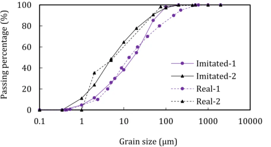
It is the best to use actual sludge. However, it is very difficult to carry a large amount of actual sludge to Japan. Therefore, the imitated-sludge was decided to use. In order to make the imitated-sludge, clay and silt should be mixed. However, the mass ratio between clay and silt is the next issue. Thus, particles size distributions of actual sludge were tested. In Figure 2-5, real-1 and real-2 are actual sludge [15]. They were taken from an under construction project. In order to imitate sludge, Kasaoka clay and silt was mixed and named as “Imitated-1” with its mass ratio of 2:3, respectively. And the “Imitated-2” was made by using only Kasaoka clay. As shown in Figure 2-5, the particles size distributions of imitated-sludge and actual sludge are almost same. This is a reason why the mass ratio 2:3 was designed. Table 2-4 is the physical properties of imitated-sludge. Table 2-5 shows chemical component of Kasaoka clay and silt.
Figure 2-5 Grain size distribution of actual sludge and imitated-sludge
0 20 40 60 80 100 0.1 1 10 100 1000 10000 Pa ss in g pe rc en ta ge ( %) Grain size (μm) Imitated-1 Imitated-2 Real-1 Real-2
Table 2-4 Physical and mechanical properties of imitated-sludge
Properties Imintation sludge Actual sludge
Type 1 Type 2 Sample 1 Sample 2
D50 (µm) 17.24 4.58 13.39 5.26
Density of soil particles, s (kg/m3) 2467 2741 2332 2636
Liquid limit, LL (%) 46.1 53.8 59.0 76.2
Plastic limit, PL (%) 29.4 11.1 26.7 32.1
Plastic index, PI (%) 16.7 42.7 32.2 44.1
Table 2-5 Chemical component clay and silt
Element Na2O MgO Al2O3 SiO2 K2O CaO TiO2 MnO Fe2O3
Silt (%) 1.97 0.28 12.88 77.85 2.42 1.89 0.11 0.07 2.08
Kasaoka clay (%) 1.48 0.81 20.22 69.07 2.75 0.91 0.63 0.03 5.46
2.3 Experimental results and discussions
2.3.1 Strength characteristics
(1) Experimental apparatus
Figure 2-6 is soil mixer. And Figure 2-8 shows the metal mold (100mm in height and 50mm in diameter) and rammer (weight: 1.5kg, free-fall height: 20cm). Figure 2-7 is oven. The curing temperature was set at 200C [14], [16]–[18]. Figure 2-9 is outline of
unconfined compression test.
Figure 2-6 Mixing machine
Figure 2-7 Yamato DKN 810 Convection Oven
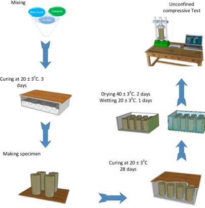
Figure 2-9 Outline of unconfined compressive test Sludge Cement Rice husk Mixing Curing at 20 ± 30C. 3 days Making specimen Unconfined compressive Test Curing at 20 ± 30C. 7 days
Figure 2-10 Procedure of compaction method
(2) Experimental procedures
Testing procedure is as follows and shown schematically in Figure 2-10. Imitated-sludge were made by mixing clay, silt, and water.
Cement and RH were added to make modified-sludge followed by carefully curing at 20 ± 30C for 3 days as initial curing period.
Specimens were made by compaction method at four layers (5times for 1st
Unconfined compression tests were carried out.
(3) Results and discussions
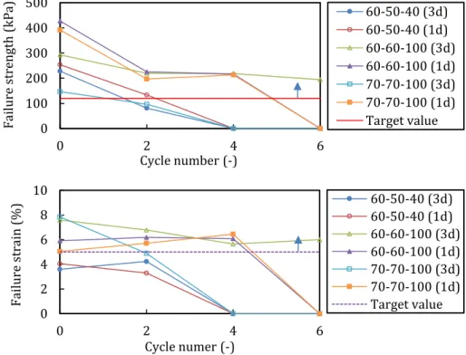
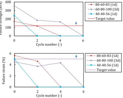
Unconfined compression tests were employed to investigate effects of rice husk, cement inclusion on failure strength-strain of modified-sludge. Target value of failure strain was set to ≥ 5% and ≥ 120kPa for failure strength [16]. The target value for failure strength was determined based on guidelines for recycling construction sludge [19]. According to the guidelines the minimum soil strength for construction machines can move on is 800kPa with the uniform soil coefficient from 6.5 to 10. So that, the failure strength of soil, s, is no lower than q. The value of q is calculated as follows: q = 800/(6.5~10) = 80~123 (kPa). The target value for failure strain was set to ≥ 2 times of failure strain of cemented-soil [20]. It has determined based on experimental results of fiber-cement-stabilized soil and cement-stabilized soil [1], [14], [16]–[18], [20]–[23]. Testing conditions are shown in Table 2-6 and Table 2-7.
Table 2-6 Mixing conditions for Imitated sludge-1 and Japanese RH
Initial water content (w)
(%) Cement content (C) (kg/m3) Rice husk content (RH) (kg/m3)
40 20, 40, 50 40, 60, 80, 100 50 30, 40, 50 60 40, 50, 60 70 50, 60, 70 80 60, 80, 100
Table 2-7 Mixing conditions for several rice husk contents
Condition (%) w (kg/m C 3) (kg/mRH 3) Imitated sludge-1 Japanese RH Imitated sludge-2 Vietnamese RH Imitated sludge-2 Japanese RH 40 40 56 50 40 43 60 50 40 70 60 73 80 60 83
Effects of Japanese RH & cement inclusion on failure strength & failure strain of the modified-imitated sludge-1 are shown in Figure 2-11. Effects of increasing of cement content were variety with different sludge’s initial water content as well as RH content. At the same RH content, the failure strength increased with increasing the cement content. Regarding to failure strain, the increasing of cement content made the
However, Figure 2-11(c, i) showed a different tendency compared to the rest of results. At maximum additive amount of cement content (50kg/m3 and 100kg/m3 for
initial water content 50% and 80%, respectively), the failure strength decreased when the RH increased from 80 to 100kg/m3. There results showed an upper limit of additive
amount of cement and RH inclusion into the modified-sludge. Therefore, if the cement and RH are added more than the upper limit, the failure strength will decrease.
Figure 2-11 indicates that the influences of RH increasing on failure strength were shown in three tendencies. There were entirely increasing, entirely decreasing or firstly increasing and after that decreasing of failure strength.
The entirely increasing of failure strength was the most common. The entirely decreasing of failure strength could be withdrawn from results of mixing conditions at low initial water content with high cement adding (such as 40% initial water content with 50kg/m3 cement content, or 50% initial water content with 40kg/m3 cement
content). The reasons for this trend may explained by the combination between cement and RH at the secondary period of curing. At the first period of curing, the cement’s hydration in rice husk-cement-reinforced sludge was able to link the RH and soil particles. However, at the secondary curing period to make specimen, the composite was broken and compact. The linking between soil particles and RH was significantly destroyed. If the cement content was added too much, the cement’s hydration occurred at high rate. The free water content in the composite was decreased. It made the soil to become too loose and dry. Therefore, the free water content in the composite was not enough for cement’s hydration to remake the linking between RH and soil particles. Moreover, if too much RH is added, the problem is scaled up, especially at low initial water content sludge and high cement and RH content. The last tendency showed maximum additive amount of RH content. Before the maximum RH content, the failure strength increases and after that the failure strength will decrease.
The effects of RH inclusion on failure strain was to increase the value. In order words, it reduced the brittleness of the modified-sludge.
(a) (b) (c) (d) (e) (f) 0 100 200 300 400 500 20 40 60 80 100 120 W = 40% C 20 C 40 C 50 Target value RH (kg/m3) Fa ilure s tr en gth (k Pa ) 0 5 10 15 20 20 40 60 80 100 120 W = 40% C 20 C 40 C 50 Target value RH (kg/m3) Fa ilure s tr ain ( %) 0 75 150 225 300 20 40 60 80 100 120 W = 50 % C 30 C 40 C 50 Target value Fa ilure s te ngth (k Pa ) RH (kg/m3) 0 5 10 15 20 20 40 60 80 100 120 W = 50 % C 30 C 40 C 50 Target value Fa ilure s tr ain ( %) RH (kg/m3) 0 75 150 225 300 375 20 40 60 80 100 120 W = 60% C 40 C 50 C 60 Target value RH (kg/m3) Fa ilure s tr en gth (k Pa ) 0 5 10 15 20 40 60 80 100 120 W = 60% C 40 C 50 C 60 Target value RH (kg/m3) Fa ilure s tr ain ( %)
(g) (h)
(i) (j)
Figure 2-11 Relationship between the failure strength, strain and rice husk content
Figure 2-12 Optimum amount of RH content of 40 % initial water content sludge
Compared to two target values, optimum conditions for each initial water content were determined by linear interpolation method. The optimum condition is defined as a minimum amount of adding materials that satisfies two target values. The optimum
0 75 150 225 300 375 20 40 60 80 100 120 W = 70 % C 50 C 60 C 70 Target value Fa ilure s te ngth (k Pa ) RH (kg/m3) 0 2 4 6 8 20 40 60 80 100 120 W = 70 % C 50 C 60 C 70 Target value Fa ilure s tr ain ( %) RH (kg/m3) 0 75 150 225 300 375 450 20 40 60 80 100 120 W = 80 % C 60 C 80 C 100 Target value RH (kg/m3) Fa ilure s tr en gth (k Pa ) 0 2 4 6 8 10 20 40 60 80 100 120 W = 80 % C 60 C 80 C 100 Target value RH (kg/m3) Fa ilure s tr ain ( %) 0.0 2.5 5.0 7.5 10.0 20 40 60 80 100 120 C 40 Target value RH (kg/m3) Fa ilure s tr ain ( %)
![Figure 1-3 Map of the Mekong Delta Transport Infrastructure Development Project (WB5) [9]](https://thumb-ap.123doks.com/thumbv2/123deta/5914448.1050581/17.892.249.668.526.878/figure-map-mekong-delta-transport-infrastructure-development-project.webp)
![Figure 1-4 shows a map of schematic presentation of urban and rural flood protection in the Mekong Delta [3]](https://thumb-ap.123doks.com/thumbv2/123deta/5914448.1050581/18.892.171.701.733.999/figure-shows-schematic-presentation-urban-protection-mekong-delta.webp)