Basic Numerical Study on Gap Influence of Residual Stress and Distortion during High-Brightness Laser Butt Welding
7
0
0
全文
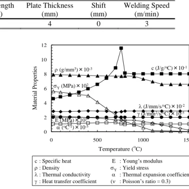
(2) Basic Numerical Study on Gap Influence of Residual Stress & Distortion during Laser Butt Welding Table 1. Power (kW) 4. Beam Spot (mm) 0.2. Experimental welding conditions of fiber laser butt welding for F82H plates.. GAS Flow (L/min) 40. Focal Length (mm) 0. Plate Thickness (mm) 4. Shift (mm) 0. Welding Speed (m/min) 3. 12. Material Properties. 10. VY (MPa)㽢102. 6 4. O (J/mm/s/oC)㽢10-2 J (J/mm2/s/oC)㽢10-5. 2. Fig. 2. Microstructural image of penetration obtained by butt welding without gap.. c (J/g/oC)㽢10-1. U (g/mm3)㽢10-3. 8. E (MPa)㽢105 D (oC-1)㽢10-5. 0 0. 500. 1000. 1500. Temperature (oC) c : Specific heat U : Density O : Thermal conductivity J : Heat transfer coefficient. Fig. 4. : Young’s modulus : Yield stress : Thermal expansion coefficient : Poisson’s ratio = 0.3). Temperature dependent material properties of F82H.. by high-power fiber laser, thermal elastic-plastic finite element analyses were conducted by changing the gap width, beam position, welding speed, and position of jig. In addition, in order to demonstrate the change of gap width during the welding, a new finite element was developed.. (a) Experimental mechanical boundary condition. Fig. 3. E VY D (Q. 2. Method of Analysis 2.1 Model for analysis According to our experimental tests using 4kW fiber laser, butt welding of two plates was modeled for this analysis10-12). Where the size of plate was 100 mm in length, 50 mm in width and 4 mm in thickness, and the material of plates was set as F82H. In the experiment, butt welding without gap was conducted and Fig. 2 shows the penetration shape, where the welding conditions are summarized in Table 1. As shown in Fig. 2, the two plates were fully penetrated through the thickness without cracks and pores. Because the diameter of fiber laser at the focal position was only 0.2 mm as shown in Table 1, the gap width was varied from 0.1 to 0.25 mm. In order to study the effect of total heat input on the welding distortion and the residual stress, the welding speed was changed from 2 to 4 m/min. In addition, the influence of beam position was studied by setting the beam to the edge of plate and changing the gap width from 0.1 to 0.3 mm. Also, as a preliminary study for the influence of jig position, the position of fixture during welding was varied. One was the condition as same as the experiment, while the fixtures were set near the weld line in another condition as shown in Fig. 3. The total number of elements and nodes are 56,400 and 64,230, respectively. The temperature dependent material properties of F82H were summarized in Fig. 4.. (b) Mechanical tight boundary condition Finite element mesh and boundary conditions for but welding.. welding distortion and the residual stress in comparison with TIG welding. Also, the fiber laser welding can be conducted in an inert gas atmosphere although the environment of joint has to be a vacuum during the EB welding. On the other hand, because the diameter of high-brightness laser beam is less than 0.6 mm and there would be a gap between parts due to the quality of parts, it is difficult to set the beam position to contact face between two parts during the practical butt-joint using the high-power fiber laser. In addition, although the gap between parts are generally reduced or controlled by using tack welds or jig, it is unrealistic to set a gap to zero along all the welding line of butt-joint and the gap seems to affect the welding distortion and the residual stress. So, in this research, as a basic study of gap influence on the welding residual stress and distortion of butt-joint welded. 38.
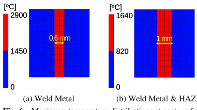
(3) Transactions of JWRI, Vol.42 (2013), No. 2 Source of heat : Power [w]. [oC] 2900. [oC] 1640. Radius of the oval : R [mm]. 0.6 mm A butting surface. 1 mm. 1450. 820. 0. 0. 䞉. 䞉 25 mm. (a) Weld Metal (b) Weld Metal & HAZ Fig. 6 Maximum temperature distributions at center of weld line without gap.. Fusion zone Location of the source of heat from the butting surface : Shift [mm]. Fig. 5. 3. Results and Discussions 3.1 Thermal analysis In order to estimate the penetration shape and the temperature history during the laser welding, the total heat input energy in the welding has to be precisely defined. However, since the thermal efficiency of fiber laser welding is unknown, the shape of ellipsoid body and the total heat input were decided through the serial computations. Where, the radiuses of ellipsoid body parallel and transverse to the weld line were set to be same because the shape of fiber laser spot is a circle. In addition, since the focal position of fiber laser was the specimen surface as shown in Table 1, a bottom half of ellipsoid body was selected as the heat input area and the density of heat input in ellipsoid body was assumed to be homogeneous. From the result of serial analyses, the radius of ellipsoid body parallel to the weld line was decided to be 0.15 mm while the depth of ellipsoid body was selected as 25 mm as shown in Fig. 5. Also, the power of ellipsoid body was defined to be 1.5 kW. Figure 6 shows the maximum temperature distributions at the center of weld line. Both the widths of weld metal and heat affected zone have the good agreements with the experimental result shown in Fig. 2. Then, by using this heat source model, the influence of gap width, beam position and welding speed on the penetration shape was examined. The maximum temperature distributions calculated were summarized in Fig. 7, where the red area indicates both weld metal and heat affected zone. In the thermal analyses, the ordinary finite elements passing through the heat source were assumed to be heated meanwhile the gap elements were not heated according to the practical laser welding without any weld wires. So, in the cases of gap width and beam position effects, the total width of red area in two plates did not change regardless of gap width. On the other hand, the width of red area increased with decreasing the welding speed because the total heat input increased.. Schematic illustration of ellipsoid body heat source model.. 2.2 Heat source model Recently, thermal elastic-plastic finite element analyses have been conducted in order to predict the welding residual stress and distortion13-15), where the transient temperature histories are obtained through the thermal analysis and then the elastic-plastic analysis are conducted in general. So, in order to predict the welding residual stress and deformation precisely, the transient temperature histories have to be demonstrated accurately. However, because the temperature histories were not measured in our experiment, an appropriate heat source model was decided so that the penetration shape could be demonstrated. In this research, a volumetric heat source model, whose shape was an ellipsoid body, was employed. 2.3 Gap element During the butt welding, the gap width between two plates seems to change before the weld heat source comes, while the distance between two plates would be fixed by the weld metal after passing the heat source. However, this distance between two plates might change before the temperature of weld metal is higher than the mechanical melting point since its rigidity is much smaller than that of plates. So, in this study, a new gap element was developed for demonstrating such change of gap width in the finite element method. Before the weld heat comes, the elastic modulus of gap element is assumed to be much smaller than that of ordinary finite element to demonstrate the change of gap width, meanwhile the modulus of gap element changes to be much lager than that of ordinary element when the strain of gap element achieves to be -1 in order to prevent the collision of two plates. On the other hand, after passing the heat source, although the gap is considered to be filled by the weld metal, the gap width might change before cooling to the mechanical melting point. So, after cooling to the mechanical melting point, the change of gap width is prevented with the exception of thermal shrinkage. In other words, the gap element changed to be the ordinary finite element after cooling to the mechanical melting point.. 3.2 Elastic-plastic analysis 3.2.1 Effect of gap width By using the transient temperature histories, elastic-plastic analyses were conducted, where mechanical boundary conditions demonstrating experimental fixtures were applied. The influence of. 39. the the the gap.
(4) Basic Numerical Study on Gap Influence of Residual Stress & Distortion during Laser Butt Welding. GAP0.1mm. GAP0.15mm. [MPa] 600 550 500 450 400 350 300 250 200 150 100 50 0. [oC] 1640. 820. GAP0.2mm. 0. GAP0.25mm. Fig. 8. (a) Influence of gap width. GAP : 0.1mm Beam shift : 0.05mm. GAP : 0.2mm Beam shift : 0.10mm. (b) Influence of beam position. Fig. 9 Welding Speed 2m/min. Fig. 7. Welding Speed 3m/min. 0.15 mm. 0.20 mm. 0.25 mm. Without Gap (0.01 mm). Effect of gap width on von Mises residual stress before releasing fixtures.. [MPa] 600 550 500 450 400 350 300 250 200 150 100 50 0. GAP : 0.3mm Beam shift : 0.15mm. 0.10 mm. 0.10 mm. 0.15 mm. 0.20 mm. 0.25 mm. Without Gap (0.01 mm). Effect of gap width on von Mises residual stress after releasing fixtures.. Welding Speed 4m/min. (c) Influence of welding speed Maximum temperature distributions at center of weld line with gap.. [mm] 0.030 0.025 0.020. width on the von Mises residual stress distribution is summarized in Fig. 8. Also, the result demonstrating without gap is shown in this figure, where a gap width was set as 0.01 mm not 0.00 mm in order to avoid the numerical instability. From this figure, it is considered that the fixtures would affect these residual distributions in the cases with the gap. So, the additional computation demonstrating the free of fixtures was conducted and the results are summarized in Fig. 9. This figure indicates that the von Mises residual stress seems not to be influenced by the gap width although the little differences can be seen at both beginning and ending edges. As same as the von Mises residual stress, the longitudinal and transverse residual stresses were found to be almost independent of the gap width. In addition, there were not seen any large differences between the longitudinal distributions, while the transverse shrinkage was affected by the gap as shown in Fig. 10. With increasing the gap width, the transverse shrinkage slightly increased, while the transverse shrinkage without gap is much smaller than that with a gap as shown in this figure. One possible reason of this difference seems to be caused by the shrinkage of gap during the welding in the cases with the. 0.015 0.010 0.005. 0.10 mm. 0.15 mm. 0.20 mm. 0.25 mm. 0. Without Gap (0.01 mm). -0.005 -0.010 -0.015 -0.020 -0.025. Fig. 10. Effect of gap width on transverse shrinkage after releasing fixtures.. gap. On the other hand, the reason why the gap width did not affect the transverse shrinkage might be caused by the fixture during the welding. 3.2.2 Effect of beam position In the practical butt welding with fiber laser, the laser beam would be shifted from the central line to the edge of one plate in order to prevent the passing of laser beam through the gap. So, the influence of laser beam position was examined by changing the gap width where the beam position was fixed to the edge of one plate.. 40.
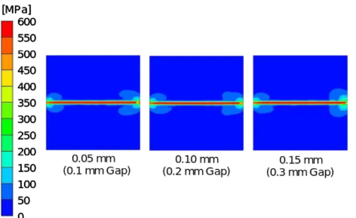
(5) Transactions of JWRI, Vol.42 (2013), No. 2 [MPa] 600 550 500 450 400 350 300 250 200 150 100 50 0. 0.05 mm (0.1 mm Gap). Fig. 11. 0.10 mm (0.2 mm Gap). [MPa] 600 550 500 450 400 350 300 250 200 150 100 50 0. 0.15 mm (0.3 mm Gap). Effect of beam position on von Mises residual stress after releasing fixtures.. Fig. 14. [mm] 0.030. [mm] 0.030. 0.025. 0.025. 0.020. 0.020. 0.015. 0.015. 0.010. 0.010. 0.005. 0.005. 0. 0. -0.005 -0.010 -0.015. 0.10 mm (0.2 mm Gap). 0.15 mm (0.3 mm Gap). -0.010. 4 m/min. Effect of welding speed on von Mises residual stress after releasing fixtures.. -0.020 -0.025. Effect of beam position on transverse shrinkage after releasing fixtures.. F82H. F82H. Fig. 15. 3 m/min. 4 m/min. Effect of welding speed on transverse shrinkage after releasing fixtures.. figure indicates that an additional weld metal should be supplied during the welding in order to obtain the sound penetration when the gap width becomes larger than 0.2 mm. However, it was found that although the diameter of spot diameter was 0.2 mm, the good penetration in the butt welding with 0.1 mm gap can be produced by controlling the beam position precisely.. F82H. 1 mm. Gap = 0.1 mm Beam Shift = 0.05 mm. 2 m/min. -0.015. -0.025. F82H. 3 m/min. -0.005 0.05 mm (0.1 mm Gap). -0.020. Fig. 12. 2 m/min. Gap = 0.2 mm Beam Shift = 0.10 mm. 3.2.3 Effect of welding speed The influences of welding speed on von Mises residual stress and transverse shrinkage are summarized in Figs. 14 and 15. With decreasing the welding speed, the residual stress increased and the large residual stress widely distributed along the weld line in the case of 2 m/min welding speed. A little difference of residual stress between 3 and 4 m/min seems to be caused by a little difference of maximum temperature distributions as shown in Fig. 7. On the other hand, the maximum temperature distributions of 2 m/min drastically changed so that the residual stress became larger. In addition, the transverse shrinkage obviously increased in the case of 2 m/min. According to the welding mechanics, the transverse shrinkage seems to increase proportionally with increasing the total heat input and the total heat input is inverse proportional to the welding speed16). So, the total heat input of 2 m/min is twice as large as that of 4 m/min, while that of 3 m/min is about 1.3 times as large. Fig. 13 Microstructural images of penetration obtained by butt welding with gap.. Figures 11 and 12 show the distributions of von Mises residual stress and transverse shrinkage in the cases with the laser beam shift after releasing the fixtures. As same as the results of gap width influence, there are not any large differences in the residual stress distributions, while the transverse shrinkage slightly increased with increasing gap width. In addition, from the comparison between Figs. 10 and 12, it was found that the laser beam position also slightly affected the transverse shrinkage. However, these figures indicated that the influence of beam position on the transverse shrinkage would be smaller than that of gap width. Figure 13 shows the penetration shapes of laser butt welding with a gap conducted as our trial experiment where the beam position was set to the edge of plate. This. 41.
(6) Basic Numerical Study on Gap Influence of Residual Stress & Distortion during Laser Butt Welding [MPa] 600 550 500 450 400 350 300 250 200 150 100 50 0. Fig. 16. [mm] 0.030 0.025 0.020 0.015 0.010 0.005 0. Experimental Boundary Condition. -0.005. Tight Boundary Condition. -0.010 -0.015. Experimental Boundary Condition. Tight Boundary Condition. -0.020 -0.025. Fig. 17. Effect of jig position on von Mises residual stress after releasing fixtures.. Effect of jig position on transverse shrinkage after releasing fixtures.. (2) The change of gap width during the welding can be simulated by developing a new gap element. (3) From the serial computational results, it was found that the gap width seems to slightly affect only the transverse shrinkage under the same heat input, while this shrinkage without gap was much smaller than that with gap. (4) The results of welding speed effect indicated that both von Mises residual stress and transverse shrinkage were influenced due to the change of total heat input. (5) As a result of jig position influence, it was revealed that the residual stress was almost independent of the jig position, while the position of fixtures slightly affected the transverse shrinkage.. as that of 4 m/min. However, the width of red area in 2 m/min was about 1.73 times as wide as that in 4 m/min, and that in 3 m/min was about 1.14 times as wide as that in 4 m/min as shown in Fig. 7. In addition, the total transverse shrinkage of 2 m/min, which is obtained from the difference between maximum and minimum values, was about 2.27 times as large as that of 4 m/min, and that of 3 m/min was about 1.29 times as large as that 4 m/min. Namely, the influence of welding speed on the transverse shrinkage in the butt welding of two plates with gap could not be explained by the ordinary theory of welding mechanics. Then, in order to reveal this effect, more additional experimental and numerical studies have to be needed. 3.2.4 Effect of jig position In the practical welding process, various types of fixture are employed during the laser welding in order to control and/or to close the gap between parts. So, the influence of jig position on the welding residual stress and distortion was examined by assuming two types of mechanical boundary conditions as shown in Fig. 3. Figures 16 and 17 show the distributions of von Mises residual stress and transverse shrinkage. From these figures, it was found that the residual stress was almost independent of the jig position, while the position of fixtures slightly affected the transverse shrinkage. In addition, by moving the fixture near the weld line, the transverse shrinkage became almost homogeneous along the weld line. So, it can be concluded that the jig position should be placed near the welding line for making the homogeneous welding deformation along the weld line.. Acknowledgements The authors would like to express his sincere appreciation to Dr. S. Ogiwara (Graduate School of Engineering, Osaka University (Current : Sumitomo Electric Industries, Ltd.)) for supporting the microstructural observations and for fruitful discussions. 1). 2). 4. Conclusions In order to examine the gap influence of the welding residual stress and distortion during the fiber laser butt welding of two plates, the thermal elastic-plastic finite element analyses were conducted by changing the gap width, beam position, welding speed, and position of jig. The conclusions can be summarized as follows. (1) By using the homogeneous ellipsoid body heat source model, the penetration shape of fiber laser butt welding can be demonstrated.. 3). 4). 42. References M. Enoeda, M. Akiba, S. Tanaka, A. Shimizu, A. Hasegawa, S. Konishi, A. Kimura, A. Kohyama, A. Sagara and T. Muroga, “Overview of Design and R&D of Test Blankets in Japan”, Fusion Engineering and Design, Vol.81, (2006), pp.415-424. H. Tanigawa, T. Hirose, K. Shiba, R. Kasada, E. Wakai, H. Serizawa, Y. Kawahito, S. Jitsukawa, A. Kimura, Y. Kohno, A. Kohyama, S. Katayama, H. Mori, K. Nishimoto, R.L. Klueh, M.A. Sokolov, R.E. Stoller and S.J. Zinkle, “Technical Issues of Reduced Activation Ferritic/Martensitic Steels for Fabrication of ITER Test Blanket Modules”, Fusion Engineering and Design, Vol.83, (2008), pp.1471-1476. Y. Gohar, M. Billone, I. Danilov, W. Dänner, M. Ferrari, K. Ioki, T. Kuroda, D. Loesser, S. Majumdar, R. Mattas, K. Mohri, R. Parker, Y. Strebkov and H. Takatsu, ITER breeding blanket design for the enhanced performance phase”, Fusion Engineering and Design, Vols.39-40, (1998), pp.601-608. D. Tsuru, H. Tanigawa, T. Hirose, K. Mohri, Y. Seki, M. Enoeda, K .Ezato, S. Suzuki, H. Nishi and M. Akiba,.
(7) Transactions of JWRI, Vol.42 (2013), No. 2 “Achievements in the Development of the Water Cooled Solid Breeder Test Blanket Module of Japan to the Milestones for Installation in ITER”, Nuclear Fusion, Vol.49, (2009), 065024 (8pp). 5) A. Kohyama, Y. Kohno, M. Kuroda, A. Kimura, F. Wan, “Production of Low Activation Steel; JLF-1, Large Heats – Current Status and Future Plan”, Journal of Nuclear Materials, Vols.258-263, (1998), pp.1319-1323. 6) S. Jitsukawa, A. Kimura, A. Kohyama, R.L. Klueh, A.A. Tavassoli, B. van der Schaaf, G.R. Odette, J.W. Rensman, M. Victoria and C. Petersen, “Recent Results of the Reduced Activation Ferritic/Martensitic Steel Development”, Journal of Nuclear Materials, Vols.329-333, (2004), pp.39-46. 7) H. Serizawa, S. Nakamura, M. Tanaka, Y. Kawahito, H. Tanigawa and S. Katayama, “Effect of Mechanical Restraint on Weldability of Reduced Activation Ferritic/Martensitic Steel Thick Plates”, Journal of Nuclear Materials, Vol.417 (2011), pp.55-58. 8) T. Hirose, H. Serizawa, H. Kishimoto, H. Ogiwara, H. Fujii, T. Nagasaka, R. Kasada, T. Nozawa, H. Tanigawa and K. Shiba, “Current Status and Issues in Joining Technology of Reduced Activation Ferritic/Martensitic Steel”, The Journal of the Japan Society of Plasma Science and Nuclear Fusion Research, Vol.87, No.3 (2011), pp.172-180. (in Japanese) 9) Y. Kawahito, M. Mizutani and S. Katayama, “Elucidation of High-Power Fibre Laser Welding Phenomena of Stainless Steel and Effect of Factors on Weld Geometry”, Journal of Physics D: Applied Physics, Vol.40 (2007), pp.5854-5859. 10) H. Serizawa, D. Mori, Y. Shirai, H. Ogiwara and H. Mori, “Weldability of Dissimilar Joint between F82H and. 11). 12). 13). 14). 15). 16). 43. SUS316L under Fiber Laser Welding”, Fusion Engineering and Design, Vol.88 (2013), pp.2466-2470. S. Komori, H. Ogiwara, K. Saida, H. Serizawa, H. Tanigawa, T. Hirose and H. Mori, “Study on Applicability of Laser Beam Welding for Reduced Activation Ferritic Steel F82H”, Proceedings of the 10th annual meeting of Japan Society of Maintenology, (2013), pp.267-270. (in Japanese) H. Ogiwara, D. Mori, H. Mori, K. Saida and H. Serizawa, “Fiber Laser Welding for Dissimilar Butt Joint of Reduced Activation Ferritic Steel/Austenite Stainless Steel”, Proceedings of the 10th annual meeting of Japan Society of Maintenology, (2013), pp.579-584. (in Japanese) H. Serizawa, S. Nakamura, H. Tanigawa, T. Hirose, M. Enoeda and H. Murakawa, “Measurement and Numerical Analysis of Welding Residual Stress in Box Structure Employed for Breeder Blanket System of ITER”, Welding in the World, Vol.55, No.11/12, (2011), pp.48-55. H. Serizawa, S. Nakamura, K. Kanbe, Y. Fujita, S. Asai and H. Murakawa, “Numerical Analysis of Deformation in Multi-pass Circumferential TIG Welding with Narrow Groove”, Welding in the World, Vol.57, Issue 5, (2013), pp.615-623. H. Serizawa, S. Nakamura, H. Tanigawa, H. Ogiwara and H. Murakawa, “Numerical Study of Local PWHT Condition for EB Welded Joint between First and Side Walls in ITER-TBM”, Journal of Nuclear Materials, Vol.442, (2013), pp.S535-S540. Y. Ueda, H. Murakawa and N. Ma, “Welding Deformation and Residual Stress Prevention”, Butterworth-Heinemann, Waltham, (2012)..
(8)
図

+3

関連したドキュメント
An easy-to-use procedure is presented for improving the ε-constraint method for computing the efficient frontier of the portfolio selection problem endowed with additional cardinality
If condition (2) holds then no line intersects all the segments AB, BC, DE, EA (if such line exists then it also intersects the segment CD by condition (2) which is impossible due
Keywords: Convex order ; Fréchet distribution ; Median ; Mittag-Leffler distribution ; Mittag- Leffler function ; Stable distribution ; Stochastic order.. AMS MSC 2010: Primary 60E05
2 Combining the lemma 5.4 with the main theorem of [SW1], we immediately obtain the following corollary.. Corollary 5.5 Let l > 3 be
Keywords: continuous time random walk, Brownian motion, collision time, skew Young tableaux, tandem queue.. AMS 2000 Subject Classification: Primary:
Inside this class, we identify a new subclass of Liouvillian integrable systems, under suitable conditions such Liouvillian integrable systems can have at most one limit cycle, and
Then it follows immediately from a suitable version of “Hensel’s Lemma” [cf., e.g., the argument of [4], Lemma 2.1] that S may be obtained, as the notation suggests, as the m A
We try to cover this gap by starting in this paper with the study of the spatial behaviour for the harmonic vibrations of thin elastic plates, while the transient solutions will
