EFFECTIVENESS OF LOG PILING AGAINST LIQUEFACTION
October 2014
Saima RIAZ
i
EFFECTIVENESS OF LOG PILING AGAINST LIQUEFACTION
October 2014
Waseda University
Graduate School of Creative Science and Engineering Department of Civil and Environmental Engineering
Research on Structural Engineering
Saima RIAZ
ii
Masanori Hamada Hirokazu Akagi Osamu Kiyomiya
Waseda University, Tokyo, Japan
2014
iii
By
SAIMA RIAZ
2014
iv
Whose uniqueness oneness &
wholeness is unchangeable. All
respects are for His Holy
Prophet, Muhammad (peace be
upon him) who enabled us to
recognize our Creator.
v
my interest in pursuing higher education, who are praying for me and who provided me with support, help and encouragement every moment along the
long academic road that I have followed
To my best friend and my Fiancé, Muhammad Shehzad Khalid, whose love makes everything worthwhile and brightens my every day
To Professor Osamu Kiyomiya and ProfessorMasanori Hamada, who helped
me to achieve this goal
vi
Seismic activity in South Asia is direct result of the collision of the Indian and the Eurasian plates, which results from the northwestern motion of the Indian Plate at the rate of 4-5 cm per year. The resulting collision has fractured the Indian plate into several slices beneath the Kashmir Basin and is known as the Indus-Kohistan seismic zone. The 2005 Kashmir earthquake hit the northwest part of Pakistan on October 08, 2005. At that time, I was an undergraduate student at University of Engineering and Technology Lahore. Despite being located approximately 250km away from the epicenter, the strong ground motion shook everything around me and my heart caused landslides and damage to life and infrastructure on an enormous scale. In addition, thousands of lives are lost every year all around the world due to this natural disaster. Sever earthquake lead to miseries to human life as well as damages to land and property due to ground motion, liquefaction and landslides etc.
After the earthquake, I visited the earthquake damage areas, Mansehra, Muzaffarabad and Balakot; the damage scenes left deep impact on my mind. Foundation failures were one of the typical seismic geo-hazards during the 2005 Kashmir earthquake, which caused a large amount of disasters and casualties. After the earthquake of October 2005, this aspect of structural design has gained importance in Pakistan. This particular design aspect is now being appreciated by the designers and there is a need to improve local skills and knowledge in this field. The increasing trend of high-rise buildings also necessitates the importance given to this field. For study in the
advance technology of Japan has no comparison with others. Therefore, my goal was to learn maximum from its advance technology. My curiosity was further enhanced when an intense earthquake (Mw=9.0) hit the Tohoku and Kanto regions of Japan in 2011 causing extensive damage to life and property because of intensive earthquake motion. From that moment, I planned to study about earthquake engineering, reasons of foundation failures during earthquakes and liquefaction damages. Hence, my study on earthquake engineering began with the liquefaction damage during the Great East Japan earthquake in 2011 and to develop a countermeasure against liquefaction.
The work presented in this thesis was initiated from October 2011 when I was admitted as a doctorate program student in Waseda University. The thesis mainly consists of four parts; the first part reported the overview of the Great East Japan earthquake and influential factors affecting liquefaction susceptibility and various countermeasures used against liquefaction damages. The
vii
effectiveness by using log piles. The third part reported seismic performance of log pile reinforcement against liquefaction based on field investigation. .The forth part concluded the research findings drawn from the extensive laboratory and field study carried out. The implications of this research also discussed and further research needs for future mitigation of liquefaction damage are identified.
Saima Riaz
viii
First, I am extremely grateful to my God, Allah, for being an intangible driving force throughout my life; I would express my sincere and profound gratitude to my supervisors, Prof. Osamu Kiyomiya and Prof. Masanori Hamada. Their advice, support, knowledge, insight and enthusiasm have been invaluable to me throughout the course of this research, and have helped to make my time an enjoyable one. Without their guidance and persistent help, this thesis would not have been possible. Throughout my thesis-writing period, they provided sound advice, good company and many good ideas. I am indebted to them more than they know. I gratefully acknowledge my committee members, Prof. Hirokazu Akagi and Prof. Masanori Hamada for their valuable comments.
I would also like to acknowledge all members of Hamada Laboratory for their assistance rendered throughout the study; especially I would like to mention the laboratory secretary Ms. Tamami Koyama, Ms. Ritsu Asaoka and my colleagues Ikki Kato, Namyi Yun and Deping Guo. Their selfless, heart whelming help and encouragement have contributed many joyful moments.
I also express my special appreciation to Dr. Shigero Miwa and Dr. Atsunori Numata, Tobishima Corporation, for their advice, productive criticism, and comments were of utmost significance to me. Their valuable suggestions and friendly counseling made it possible to achieve my objectives thus paved my way to success. Above all and the most needed, they provided me persistent invigoration and encouragement in various ways. I am greatly thankful to all my teammates in geotechnical laboratory for their prodigious support in the laboratory and field-testing and for making the work environment convivial.
Financial support for this research was generously provided by Waseda University. I am extremely thankful for this support, which helped make this study possible.
I am also thankful to University of Engineering & Technology Lahore (UET Lahore) to grant me leave for higher studies. I would like to express my warmest thanks to all my colleagues at Geological Engineering Department for their friendship and help, especially Prof. Dr. Naseem Aadil and Prof. Dr. Muhammad Saleem Khan for supporting me and encouraging me to go for higher education in Japan.
Special thanks are extended to those persons who participated and helped me in direct and indirect way. This thesis is not only the work of mine but also those who remained involve in the
ix
possible.Last but not least, I am eternally obliged to my mother (Late) and father, my sisters and brothers for everything, which cannot be put into words, despite their physical absence their love and prayers has helped me in the successful fulfillment of my study at Waseda University. This dissertation is dedicated to the loving memory of my dear mother. She was a woman of impeccable ethos. She was very proud of my development as a person and my scientific and professional progress but she was also looking forward to the quick completion of this dissertation and my going back home again. Unfortunately, she is not here with us to see the whole thing finished. However, her unexpected and tragic death opened my eyes to life and helped me re- estimate and re-value my own life. I am sure she is somewhere out there always watching us closely. Words fail me to express my gratitude to my best friend and my Fiancé, Muhammad Shehzad Khalid. I owe him for his patience and understanding, for his continuous support, love and dedication during this long period.
Finally, I would like to thank Japan for being my home for the last three years, and Waseda University for being such a wonderful environment in which to do a PhD.
SAIMA RIAZ
x
Liquefaction of soils in response to earthquake shaking is a burning issue after the 1964 Niigata &
Alaska earthquakes, 1983 Nihonkai-chubu and 2011 off the Pacific Tohoku earthquakes in Japan.
Research on the liquefaction started just after the Niigata earthquake. However, the 1995 Hyogoken-nambu earthquake and recently after 2011 Tohoku earthquakes accelerated the studies because the damage to buildings, roads and bridges was severe. After these earthquakes many studies have been conducted based on shaking table tests and analyses.
A number of remediation methods exist, which reduce the excess pore pressure, enhance the shear deformability of the soil and densify the soil. Two well-known methods, which are log piles and densification, are discussed and compared in this study. For this purpose, sand samples were collected from different locations for subsequent laboratory testing purpose. The experimental study was mainly aimed at evaluating the effect of log piles and density increase on liquefaction strength of soil and to develop a liquefaction countermeasure technique. Index properties of soils such as Grain size analysis, water content and specific gravity were determined for selected soil samples. A series of precisely prepared 1-g shaking table tests were carried out regarding these methods. Shaking table tests were performed on unimproved soil (natural soil), soil with increasing density (compacted soil) and on the soil improved by using wooden piles. A total of 27 shaking table tests of different scales (small scale, medium scale and large scale) were conducted on five different types of sands (Toyoura, Tonegawa, Urayasu, Silica and Kasumigaura). Effects of excess pore pressure generation on settlement of structure, time history during shaking and relative density on cumulative settlement are discussed. Liquefaction potential of all sands is calculated and comparing the results obtained. Finally, geotechnical investigations, consisting of Portable Dynamic Cone Penetration (PDCP), Swedish Weight Sounding (SWS), Automatic Ram Sounding (ARS), Piezo Drive Cone (PDC) and Flat Dilatometer test (DMT) were performed to confirm the effectiveness of log piling method and compare the results with densification method.
The influence of relative density, excess pore water pressure and effective confining pressure on settlement of structure and liquefaction potential of sands was also investigated. The results show that log piling method was more beneficial than densification method in the case of liquefaction resistance and settlement of the structure during the shaking period.
Various in-situ tests were also conducted to investigate the practicality of this method. During Great East Japan Earthquake in 2011, liquefaction was pervasive in large portions of the region
xi
extensive damage to residential properties, electricity, water and sewage networks and bridges.
Ground improvement comprises of a 15m wide strip in Maihama, Urayasu city along the Tokyo bay by driving 160mm diameter wooden piles. Site area was divided into different blocks (A, C, E) each of 5m x 5m grid with different pile spacing. 100, 64 and 36 number of piles was installed in Block E, C and A respectively with c/c spacing between piles is 3D, 4D and 5D whereas D is the diameter of pile. These wooden piles stiffen the ground reducing the potential for liquefaction and penetrate the alluvial soil underneath by crossing reclaimed soil to provide restraint against liquefaction and lateral spreading of ground. A total of 32 In-situ tests were performed including Standard Penetration test (SPT), Swedish Weight Sounding (SWS), Portable Dynamic Cone Penetration (PDCP), Automatic Ram Sounding (ARS), Piezo Drive Cone (PDC) were conducted in actual field condition. Liquefaction analysis was done from the N-values obtained from field tests using two guidelines, Specifications for Highway Bridges and Recommendations for Design of Building Foundations.
The geotechnical investigations and assessment of the site indicated that safe side design for log piling method could be possible for liquefaction mitigation due to estimating liquefaction resistance factor (liquefaction potential) from calculated ground density between piling logs.
Liquefaction resistance factor,FLis calculated from the mean values of the SPT data. From these values, the factor of safety against liquefaction has been calculated and a comparative assessment has been done considering the soil having more liquefactio
resistance is equal to 2 or more than 2 in every case, therefore, log piling method is failsafe against liquefaction and also improves the ground.
Key words: Liquefaction, shaking table, liquefaction potential, log piles, ground improvement
Table of Contents
1 INTRODUCTION
...1
1.1 Introduction ...1
1.2 Aims and objectives of research...2
1.3 Scope of research ...2
1.4 Research methodology ...2
1.5 Organization of the thesis...3
2 LITERATURE REVIEW
...7
2.1 Introduction ...7
2.2 Liquefaction phenomenon...7
2.3 Failure types and factors affecting liquefaction susceptibility...8
2.3.1 Failure types ...8
2.3.2 Factors affecting liquefaction susceptibility...10
2.4 Reviews of previous researchers on liquefaction susceptibility...14
2.4.1 Evaluation and propitiation of the Results of Previous Researches15
2.5 Summary ...26
3 MATERIALS USED AND EXPERIMENTAL SETUP FOR SHAKING TABLE TESTS
...33
3.1 Introduction ...33
3.2 Testing material...33
3.2.1 Toyoura sand ...33
3.2.2 Tonegawa sand ...33
3.2.3 Silica sand...33
3.2.4 Urayasu sand ...34
3.2.5 Kasumigaura sand ...34
3.3 Index properties of sands...34
3.4 Grain size characteristics...34
3.4.1 Maximum and minimum void ratios ...36
3.4.2 Specific gravity...36
3.5 Shaking table ...36
3.6 Studied cases ...37
3.7 Preparation of model ground for small scale shaking table test...44
3.7.1 Increasing density method...44
3.7.2 Premaking by frozen method...44
3.7.3 Log piling method ...44
3.8 Preparation of model ground for medium scale shaking table test ...45
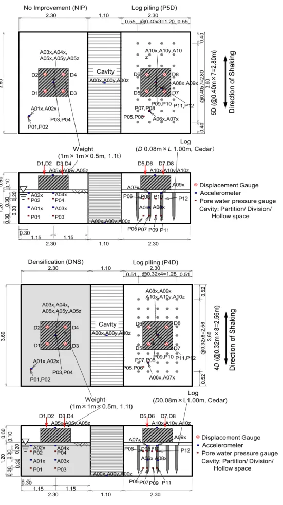
3.9 Preparation of model grounds for large scale shaking table test...48
3.9.1 Container and arrangement of sensors...48
3.9.2 Natural model ground (NIP)...48
3.9.4 Compacted model ground (DNS) ...50
3.10 Summary...52
4 EFFECTIVENESS OF LOG PILING AGAINST LIQUEFACTION BY SHAKING TABLE TESTS...54
4.1 Introduction ...54
4.2 Utilization of wood as structural element ...54
4.3 Findings of the current study...55
4.3.1 Input motion ...55
4.3.2 Pore pressure generation...57
4.3.3 Settlement of structures ...61
4.3.4 Liquefaction assessment ...69
4.4 Ground investigation between logs ...71
4.4.1 Sounding tests...71
4.5 Verification of remedial measures ...77
4.6 Summary ...79
5 FIELD TESTS ON EFFECTIVENESS OF LOG PILING AGAINST LIQUEFACTION IN URAYASU
...82
5.1 Introduction ...82
5.2 Site description...82
5.3 Geotechnical investigations...82
5.3.1 Soil profile...83
5.4 Ground improvement construction...86
5.5 In-situ testing between logs...87
5.5.1 Measurement of blow counts (N-value) by in-situ tests...87
5.5.2 Determination of the liquefaction potential...97
5.6 Summary ...104
6 CONCLUSIONS AND RECOMENDATIONS
...106
6.1 Introduction ...106
6.2 Conclusions and implications of findings ...107
6.3 Future recommendations ...108
List of Figures
Figure 1-1Research flow chart and graphic abstract ...4
Figure 2-1Lateral spread before and after liquefaction (Youd, 1984) ...9
Figure 2-2Ground oscillation before and after liquefaction (Youd, 1984) ...10
Figure 2-3Limits in the gradation curves separating liquefiable and nonliquefiable soils (Tsuchida, 1970)... 11
Figure 2-4Proposed boundary curves for site identification of liquefaction-induced damage (Ishihara, 1985) ...14
Figure 2-5Relationship between volumetric strain, induced strain and relative density for sands (after Tokimatsu et al. 1987)...16
Figure 3-1Grain size distributions of sands ...36
Figure 3-2Shaking tables ...37
Figure 3-3(a) Full Reinforcement (Urayasu sand)...47
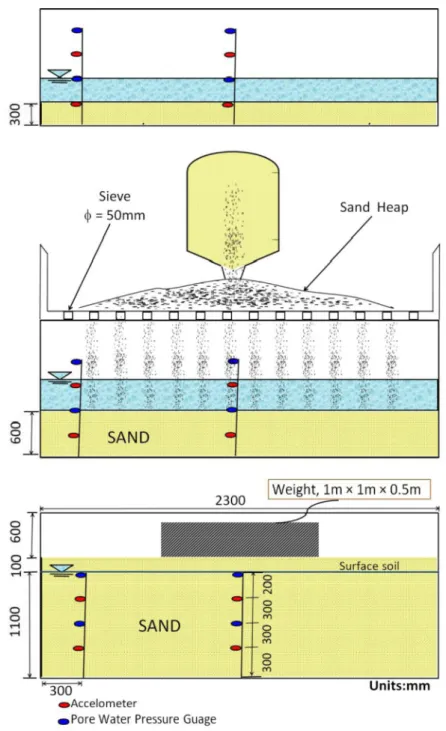
Figure 3-4Preparation of unimproved model ground ...49
Figure 3-5Preparation of log piling ground ...50
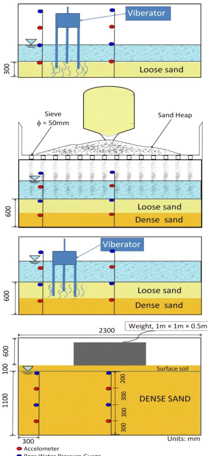
Figure 3-6Preparation for compacted model ground...51
Figure 4-1Input motions for shaking tables...56
Figure 4-2Relationship between excess pore water pressure and settlement ...58
Figure 4-3An example of time history of large scale shaking table test (target input motion 150gal)...60
Figure 4-4Relationship between input acceleration and cumulative settlement...63
Figure 4-5Relationship between relative density and settlement ...66
Figure 4-6Relationship between degree of compaction and settlement ...67
Figure 4-7Relationship between dry density and settlement ...68
Figure 4-8Relationship between relative density and cyclic resistance...70
Figure 4-9Positions of sounding tests...72
Figure 4-10Results from sounding tests ...74
Figure 4-11Relationship between relative density and N value ...75
Figure 4-12Results of DMT test ...77
Figure 4-13Relationship between shear modulus and shear strain...78
Figure 4-14Relationship between shear modulus and improvement ratio...78
Figure 5-1Soil profile of Maihama, Urayasu city...84
Figure 5-2Location of in-situ tests performed in Maihama, Urayasu city...84
Figure 5-3Wooden Pile Ground Improvement ...87
Figure 5-4SPT Results (Variation of N-values with depth) ...88
Figure 5-5SWS results (Variation of N-values with depth)...89
Figure 5-6PDCPT results (Variation of N-values with depth)...89
Figure 5-7ARS results (Variation of N-values with depth)...90
Figure 5-8PDC results (Variation of N-values with depth) ...90
Figure 5-9Relationship between SPT N-values and improvement ratio ...91
Figure 5-10Relationship between SWS N-values and improvement ratio ...92
Figure 5-11Relationship between PDCPT N-values and improvement ratio ...93
Figure 5-12Relationship between ARS N-values and improvement ratio...94
Figure 5-14Liquefaction potential of Urayasu soil...103
List of Table
Table 2-1Summary of literature review on the liquefaction resistance of sandy soils and different
countermeasures against liquefaction...18
Table 3-1Index properties of sands ...35
Table 3-2Studied Cases...39
Table 3-3Summary of ground preparation methods ...46
Table 5-1Geotechnical Investigation of site...83
Table 5-2Construction specifications for log piling in Maihama, Urayasu ...85
List of Symbols
s Density of soil particles emax Maximum void ratio emin Minimum void ratio
D50 Mean grain size
Uc Uniformity coefficient
dminJIS Minimum density (Japan Industrial Standards method) emaxJIS Maximum void ratio (Japan Industrial Standards method)
dmaxJIS Maximum density (Japan Industrial Standards method) eminJIS Minimum void ratio (Japan Industrial Standards method)
dmaxmm Maximum density (Minimum method)
eminmm Minimum Void ratio (Minimum method)
Dmax Maximum grain size
Pf Fine fraction
wL Liquid limit
wP Plastic limit
Ip Plasticity index
Gs Specific gravity
STT Shaking table test
NIP No improvement ground
P3D Log piling ground with interval between piles is 3 times diameter the pile P4D Log piling ground with interval between piles is 4 times diameter the pile P5D Log piling ground with interval between piles is 5 times diameter the pile P6D Log piling ground with interval between piles is 6 times diameter the pile P8D Log piling ground with interval between piles is 8 times diameter the pile DNS Densification method
Dro Initial Relative density before piling logs Do Relative density after piling logs
GSL Ground surface level
GWL Ground water level
Dr Relative density assumed between the logs
D Displacement gauge
A Accelerometer
P Pore water pressure gauge Gal Galileo (Acceleration unit)
v Effective overburden pressure
d Dry unit weight of soil
sat Saturated unit weight of soil
w Unit weight of water
u/ Excess pore water pressure ratio Ai Input acceleration
S Settlement of structure
DA Double amplitude
R20 Cyclic resistance ratio
d Shear stress
t Total density of element
Drmm Relative density (Minimum Method) PDCPT Portable dynamic cone penetration test SWS Swedish weight sounding test
PDC Piezo drive cone test
ARS Automatic ram sounding test DMT Flat dilatometer test
SPT Standard penetration test
G Shear modulus
B Pile interval
FL Liquefaction resistance factor
1 INTRODUCTION
1.1 'Introduction
weaken, liquefaction is the term commonly used to describe the sudden, dramatic strength loss which sometimes occurs in sands during seismic loading. While most frequently associated with cohesionless soils and dynamic loadings, it has been reported in many types of soils under both dynamic and static loadings (Polito, 1999).
Soil liquefaction caused severe damage of foundations, lifelines, and water front structures.
Excessive settlements, lateral spreading of ground and landslides were induced by liquefaction.
The liquefaction of sands during earthquakes has occurred throughout recorded history, and
certainly, research into the
subject began in earnest. Since the Good Friday earthquake (Mw=9.2) in Alaska and Niigata earthquake (Mw=7.5) in Japan, great strides have been made in understanding the mechanisms behind liquefaction and the conditions that make soils susceptible to it. Afterwards, many studies on soil liquefaction have been performed in order to understand the mechanism of liquefaction and the dynamic responses of foundations in a liquefiable soil (Ishihara and Yoshimine, 1992;
Idriss and Boulanger, 2006; Finn et al., 1971; Ishihara, 1993).
The results of these studies provided the bases for evaluation of the mitigation methods for liquefaction hazard (Hamada et al., 1996; Yoshimi and Tokimatsu, 1977; Tokimatsu, 1997; Idriss and Boulanger, 2008; Yoshida et al. 1994).
Great East Japan Earthquake in 2011 hit the Tohoku and Kanto regions causing extensive damage to life and property because of intensive earthquake motion and tsunami and damage to nuclear power plants. Despite Tokyo being located approximately 380km away from the epicenter, the ground motions observed from the earthquake were strong enough to cause significant liquefaction to lose reclaimed soils in Tokyo bay including the city of Urayasu. Many residential and commercial buildings and lifeline facilities in Urayasu city suffered extensive damage due to soil liquefaction (Tokimatsu and Katsumata, 2012; Yoshida et al., 2012; Orense, 2012; Ochi and Suzuoki, 2011).
Liquefaction of the soil causes damage to the structures that needs costly and cumbersome remedial measures and stability problems, sometimes of vital importance. Therefore, in this study, two types of remedial measures were employed; log piling and densification for liquefaction
mitigation and Liquefaction analysis was done using two guidelines, Specifications for Highway Bridges and Recommendations for Design of Building Foundations.
1.2 Aims and objectives of research
The main objectives of research were as follows:
i. Analyze the ground response of laboratory-tested soils prone to liquefaction when subjected to dynamic loading.
ii. To find a cost-effective, practical and environment friendly solution for liquefaction mitigation
iii. Investigate the effectiveness of log piles to improve the ground and the influence on liquefaction potential of the soil by in-situ tests
iv. To reveal the effectiveness of log piling against liquefaction and to compare densification method and log piling method against liquefaction.
1.3 Scope of research
In this study, particular emphasis has been laid on the determination of liquefaction potential of different sands using shaking table tests and to develop a countermeasure against liquefaction by comparing two methods (densification and log piling method). Five sand samples were collected from different locations in Japan. Not much data about the use of wood as a countermeasure against liquefaction is available. To conduct a liquefaction assessment study about wooden piles in the city of Urayasu is very beneficial because liquefaction potential parameters determined in this study can, therefore, be used as reference in future for this area. Not only the laboratory tests were performed on the ejected sand because of liquefaction during Great East Japan earthquake but also in-situ tests were conducted to check the effectiveness of wooden piles against liquefaction.
1.4 Research methodology
The methodology to be adopted for this research thesis will be based on the following steps:
i. Literature Review.
ii. Collection of sand samples from different prefectures of Japan.
iii. Performance of laboratory tests on all sands including the basic soil classification tests to determine index properties and three different scales shaking table tests (small, medium and large scale). Different sounding tests will also perform.
iv. Effectiveness of wooden piles and densification on liquefaction characteristics will be analyzed and make a comparison of two methods by soil parameters (N-values) obtained through different in-situ testing techniques.
v. Critical review of the research findings and discussion on the results.
1.5 Organization of the thesis
Chapter 1 gives a brief description of the thesis background, objectives of the thesis, scope of the investigation and the methodology.
Chapter 2 of this research gives introduction to the phenomenon of liquefaction, Failure types and factors affecting liquefaction susceptibility, Reviews of previous researchers on liquefaction susceptibility.
Chapter 3 presents details about the experimental setup used, selection of the material, type of soils and their properties and preparation of model ground for shaking table tests.
Chapter 4 explains the results obtained from laboratory tests (Small scale, Medium scale and large scale shaking experiments using log piles and densification). Input motion, Pore pressure generation, Settlement of structures and liquefaction assessment will be made based on laboratory shaking table tests.
Chapter 5 presents a comparison of various soil parameters obtained through different in-situ testing techniques in the city of Urayasu to check the practicality of log piling method.
Chapter 6 presents the conclusions, recommendations made regarding the influence of the improvement by wooden piles and the possibility of extension of this study for further research.
The research flow chart and graphic abstract is shown in Figure 1-1.
References:
1) Polito, P.C., 1999. The Effects of Non-Plastic and Plastic Fines on the Liquefaction of Sandy Soils. PhD dissertation, Virginia Polytechnic Institute and State University.
2) Ishihara, K. and Yoshimine, M., 1992.Evaluation of settlements in sands deposits following liquefaction during earthquakes. Soils and Foundations,32(10), 173-188.
3) Idriss, I.M. and Boulanger, R.W., 2006.Semi-empirical procedures for evaluating liquefaction during earthquakes. Journal of Soil Dynamics and Earthquake Engineering, 26, 115-130.
4) Finn, W.D.L., Pickering, D.J. and Bransby, P.L., 1971. Sand liquefaction in triaxial and simple shear tests. Journal of Soil Mechanics and Foundations Division, ASCE 97, SM4, 639-659.
5) Ishihara, K., 1993.Liquefaction and flow failure during earthquakes, Geotechnique, 43(3), 321-376.
6) Hamada, M. and Wakamatsu, K., 1996.Liquefaction, Ground Deformation and their caused damage to structures, The 1995 Hyogoken-Nanbu earthquake-investigation into damage to civil engineering structures. Committee of Earthquake Engineering, Japan Society of Civil Engineers, 45-92.
7) Yoshimi, Y. and Tokimatsu, K. 1977. Settlement of buildings on saturated sand during earthquakes. Soils and Foundations, 17(1), 23-38.
8) Tokimatsu, K., 1997. Recommendations for design of building-foundations considering liquefaction and lateral spreading. The Kenchiku Gijutsu, 563,126-131. (In Japanese).
9) Idriss, I. M. and Boulanger, R. W., 2008. Soil Liquefaction during Earthquakes.
Earthquake Engineering Research Institute.
10) Yoshida, N., Yasuda, S., Kiku, M., Masuda, T. and Finn, W.D.L., 1994. Behavior of sand after liquefaction.Proceedings of 5th US-Japan Workshop on Earthquake Resistant Design of Lifeline and Countermeasures against Soil Liquefaction, 181-198.
11) Tokimatsu,K. and Katsumata, K., 2012.Liquefaction-induced damage to buildings In Urayasu city during the 2011 Tohoku Pacific Earthquake. Proceedings of the International Symposium on Engineering Lessons Learned from the 2011 Great East Japan Earthquake.
12) Yoshida, M., Miyajima, M. and Numata, A., 2012.Experimental Study on liquefaction countermeasure technique by log piling for residential houses.15thWorld Conference on earthquake Engineering,WCEE, Lisbon, Portugal.
13) Orense R.P., 2012.Soil liquefaction and slope failures during the 2011 Tohoku, Japan Earthquake. NZSEE Annual Technical Conference & AGM.
14) Ochi, S. and Suzuoki, M., 2011.The lessons of the Great East Japan Earthquake 2011 and the countermeasures against earthquakes and tsunami in future-Fundamental Concepts behind Future Tsunami Disaster Prevention. Proceedings of the 43rd joint meeting of U.S.-JAPAN panel on wind and seismic effects, UJNR, 49-60.
2 LITERATURE REVIEW
2.1 Introduction
In this chapter, an overview of available literature regarding seismic soil liquefaction engineering is presented. A brief review on the mechanism of densification and on the use of site characterization to assess ground conditions before and after ground improvement, ground improvement as a remedial measure against soil liquefaction on sandy soils and reviews the current state of knowledge that how densification is beneficial against liquefaction. The published results of geotechnical studies were discussed in order to understand the effects of liquefaction and countermeasures against soil liquefaction.
In addition, a review of literature related to liquefaction and the factors affecting liquefaction susceptibility and excess pore pressure characteristics of sandy soils. The results of the literature review areencapsulated in Table 2-1, and are presented herein.
2.2 Liquefaction phenomenon
significant loss of strength of very loose sands causing flow failures due to slight disturbance.
Similarly, Mogami and Kubo (1953) used the same term to define shear strength loss due to seismically-induced cyclic loading. However, its importance has not been fully understood until 1964 Niigata earthquake, during which the significant causes of structural damage were reported to be due to tilting and sinking of the buildings founded on saturated sandy soils with significant soil liquefaction potential (Hamada et al., 1986).
Liquefaction is, by definition, the transformation of granular soil from a solid state into a heavy fluid due to an extreme drop in strength and stiffness caused by increased pore water pressure and the resulting reduction in effective stress (Marcuson, 1978). Laboratory tests have confirmed that the liquefaction resistance is primarily a function of relative density but that confining stress, the lateral earth pressure coefficient Ko, ageing/fabric and number of cycles (Ishihara, 1996) among other factors listed in Table 2-1 also influence the susceptibility. An increase in relative density of sand, with other parameters constant, decreases the volume of voids and thus decreases the potential to contract during shearing under drained conditions and reduces the generation of positive pore pressure under undrained conditions. This can be accomplished by ground densification.
2.3 Failure types and factors affecting liquefaction susceptibility
2.3.1 Failure types
There are four basic types of ground failure that commonly result from liquefaction: flow failure, lateral spread, ground oscillation and loss of bearing capacity. Other phenomena associated with liquefaction include rise of pore water pressure, sand boils and various types of deformation. Sand boils, by themselves, are not strictly a form of ground failure, but rather are diagnostic evidence of pore water pressure buildup at depth, indicating that liquefaction has occurred.
2.3.1.1 Flow failures
Flow failures occur in sloping areas inclined at 5 percent or greater and are landslides on a very large scale. They are the most damaging type of ground failure caused by liquefaction. Flow failures occur when a mass of loose granular soil loses its strength after initial liquefaction and flows like a heavy liquid producing very large deformations. The incipient condition for the inducement of flow type deformation is closely associated with the residual strength or steady- state strength, which is mobilized in soils after they have undergone deformations. Flow failures commonly displace large masses of soil for hundreds of feet (meters).
Materials involved in flows may consist of completely liquefied soil or blocks of intact material riding on a layer of liquefied soil. Flow failures may occur in natural ground, but are also likely in man-made earth structures, such as earth dams, mine-tailing dams and fill placed behind waterfront retaining structures. The earliest known flow failures in the U.S. occurred in the 1811- 1812 New Madrid earthquake in Missouri (Fuller, 1912). More recently, the failure of the upstream slope of the Lower San Fernando Dam during the 1971 San Fernando, California, earthquake is another notable example of flow failure (Seed et al., 1975).
2.3.1.2 Lateral spreading
Lateral spreading is the most common type of ground failure triggered by liquefaction (Varnes, 1978). Primarily, it involves lateral displacement of large; blocks of intact, surficial soil because of liquefaction in underlying layers (see Figure 2-1). Other phenomena such as rotational movements and subsidence occur during lateral spreading. Lateral spreads generally develop on gentle slopes, as flat as 3 degrees, and move toward a free face, such as an incised river channel.
Permanent displacements ranging from a few inches (centimeters) to over 30 ft. (10 m) have been observed in the U.S., Japan and other countries, causing damage to embankments, buried pipelines, roads, bridges, foundations of buildings and canals (National Research Council, 1985;
Youd and Perkins, 1987). During the 1964 Alaska earthquake, for example, 266 bridges were displaced and damaged by spreading of flood plain deposits toward river channels. All of these bridges were supported on piles and in nearly all instances the tops were laterally displaced.
In their 1992 review of several hundred case histories that involve earth failures from earthquakes, Barlett and Youd found that the potential for significant lateral displacement due to liquefaction diminishes tremendously for earthquake magnitudes below 6 and that no significant lateral spreading is likely to occur in dense to very dense sands if the magnitude of the earthquake is less than 8.
Figure 2-1Lateral spread before and after liquefaction (Youd, 1984) 2.3.1.3 Ground oscillation
When the ground is too flat to permit lateral movement, liquefaction at depth may create separations at the surface by decoupling overlying soil blocks, allowing the blocks to jostle back and forth on the liquefied layer, as shown in Figure 2-2. This phenomenon of soil block jostling produces an oscillation as ground waves. It is reported (Youd, 1984) that the decoupled surface layer vibrates in a different mode than the underlying and surrounding firm ground, causing fissures to form and impacts to occur between oscillating blocks and adjacent firm ground.
Ground oscillation and associated sand boils can present an enormous clean-up problem if they occur in a built-up area. If accompanied by ground settlement, damage and disruption can also occur.
Figure 2-2Ground oscillation before and after liquefaction (Youd, 1984) 2.3.1.4 Loss of bearing capacity
When the soil supporting a structure liquefies and loses strength, large deformations can occur, leading to large settlements and/or tilting of structures. Loss of soil bearing capacity may also occur when liquefaction that has initially developed in a sand layer a few meters below a footing propagates upward through overlying sand layers and subsequently weakens the soil supporting the structure.
2.3.1.5 Effects of liquefaction on piles
During a seismic event, the dynamic response of piles will be affected by the nature of the earthquake loading, the pile and soil characteristics, and the degree of restraint applied by the superstructure to the motion of the pile. If the soil deposits at the structure site are liquefied, the pile-supported structure may be damaged or destroyed by mechanisms associated with different types of ground failure as stated in Sections 2.3.1.1 - 2.3.1.4.
2.3.2 Factors affecting liquefaction susceptibility
Based on field observation and laboratory testing results, liquefaction characteristics of cohesionless soils are affected by a number of factors:
2.3.2.1 Grain-size distribution and soil types
The type of soil most susceptible to liquefaction is one in which the resistance to deformation is mobilized by friction between particles. If other factors such as grain shape, uniformity coefficient and relative density are equal, the frictional resistance of cohesionless soil decreases as the grain size of soils becomes smaller. Tsuchida (1970) summarized the results of sieve analyses performed on a number of alluvial and diluvial soils that were known to have liquefied or not to have liquefied during earthquakes. He proposed ranges of grain size curves separating liquefiable and nonliquefiable soils as shown in Figure 2-3. The area within the two inner curves in the figure represents sands and silty sands, the soils with the lowest resistance to liquefaction. A soil with a
gradation curve falling in the zones between the outer and inner curves is less likely to liquefy.
Soils with a higher percentage of gravels tend to mobilize higher strength during shearing, and to dissipate excess pore pressures more rapidly than sands. However, there are case histories indicating that liquefaction has occurred in loose gravelly soils (Seed, 1968; Ishihara, 1985;
Andrus et al., 1991) during severe ground shaking or when the gravel layer is confined by an impervious layer. The space between the two curves farthest to the left reflects the influence of fines in reducing the tendency of sands to densify during seismic shearing. Fines with cohesion and cementation tend to make sand particles more difficult to liquefy or to seek denser arrangements. However, nonplastic fines such as rock flour, silt and tailing slimes may not have as much of this restraining effect. Ishihara (1985) stated that clay or silt-size materials having a low plasticity index value will exhibit physical characteristics resembling those of cohesionless soils and thus have a high degree of potential for liquefaction. Walker and Steward (1989) based on their extensive dynamic tests on silts, have also concluded that nonplastic and low plasticity silts, despite having their grain size distribution curves outside of Tsuchida's boundaries for soils susceptible to liquefaction, have a potential for liquefaction similar to that of sands and that increased plasticity will reduce the level of pore pressure response in silts. This reduction, however, is not significant enough to resist liquefaction for soils with plasticity indices of 5 or less.
Figure 2-3Limits in the gradation curves separating liquefiable and nonliquefiable soils (Tsuchida, 1970)
Even though major slide movements during earthquakes have occurred in clay deposits, they are commonly considered to be nonliquefiable during earthquakes in the sense that an extensive zone of clay soil is converted into a heavy fluid condition. However, it is believed that quick clays may lose most of their strength after strong shaking and that other types of clay may lose a proportion
of their strength resulting in slope failures. Frequently, landslides in clay deposits containing sand or silt lenses are initially triggered by the liquefaction of these lenses before any significant strength loss occurs in the clay. This has been supported by laboratory test results which indicate that the strain required to liquefy sands is considerably smaller than the strain required to overcome the peak strength of cohesive soils (Seed, 1968; Poulos et al., 1985).
There is also ample evidence to show that uniformly graded materials, generally having a uniformity coefficient smaller than five, are more susceptible to liquefaction than well-graded materials (Ross et al., 1969; Lee and Fitton, 1968) and that for uniformly graded soils, fine sands tend to liquefy more easily than coarse sands, gravelly soils, silts or clay.
2.3.2.2 Relative density
Laboratory test results and field case histories indicate that, for a given soil, initial void ratio or relative density is one of the most important factors controlling liquefaction. Liquefaction occurs principally in saturated clean sands and silty sands having a relative density less than 50%. For dense sands, however, their tendency to dilate during cyclic shearing will generate negative pore water pressures and increase their resistance to shear stress. The lower limit of relative density beyond which liquefaction will not occur is about 75% (State of New York, Department of Transportation Report, 2007).
2.3.2.3 Earthquake loading characteristics
The vulnerability of any cohesionless soil to liquefaction during an earthquake depends on the magnitude and number of cycles of stresses or strains induced in it by the earthquake shaking.
These in turn are related to the intensity, predominant frequency, and duration of ground shaking.
2.3.2.4 Vertical effective stress and over consolidation
It is well known that an increase in the effective vertical stress increases the bearing capacity and shear strength of soil, and thereby increases the shear stress required to cause liquefaction and decreases the potential for liquefaction. From field observations, it has been concluded by a number of investigators that saturated sands located deeper than 50 to 60 feet (15 to 18 m) are not likely to liquefy. These depths are in general agreement with (Kishida, 1969) who states that a saturated sandy soil is not liquefiable if the value of the effective overburden pressure exceeds 2 tsf (190 kN/m2).
Both theory and experimental data show that for a given soil a higher over consolidation ratio leads to higher lateral earth pressure at rest and thereby increases the shear stress ratio required to cause liquefaction.
2.3.2.5 Age and origin of the soils
Natural deposits of alluvial and fluvial origins generally have soil grains in the state of loose packing. These deposits are young, weak, free from added strength due to cementation, and aging.
Youd and Hoose (1977) stated that, as a rule of thumb, alluvial deposits older than late Pleistocene (10,000- 130,000 years) are unlikely to liquefy except under severe earthquake loading conditions, while late Holocene deposits (1,000 years or less) are most likely to liquefy, and earlier Holocene (1,000-10,000 years) deposits are moderately liquefiable.
2.3.2.6 Seismic strain history
It has been demonstrated from laboratory test results that prior seismic strain history can significantly affect the resistance of soils to liquefaction (Finn et al., 1970; Seed et al., 1977;
Singh et al., 1980). Low levels of prior seismic strain history, because of a series of previous shakings producing low levels of excess pore pressure, can significantly increase soil resistance to pore pressure buildup during subsequent cyclic loading. This increased resistance may result from uniform densification of the soil or from better interlocking of the particles in the original structure due to elimination of small local instabilities at the contact points without any general structural rearrangement taking place. Large strains, however, associated with large pore pressure generation and conditions of full liquefaction can develop weak zones in the soil due to uneven densification and redistribution of water content (National Research Council, 1985; Whitman, 1985), and thus lower the resistance of the soil to pore pressure generation during subsequent cyclic loading.
2.3.2.7 Degree of saturation
Liquefaction will not occur in dry soils. Only settlement, because of densification during shaking, may be of some concern. Very little is known on the liquefaction potential of partially saturated sands. Available laboratory test results (Sherif et al., 1977) show liquefaction resistance for soils increases with decreasing degree of saturation, and that sand samples with low degree of saturation can become liquefied only under severe and long duration of earthquake shaking.
2.3.2.8 Thickness of sand layer
In order to induce immense damage at level ground surface from liquefaction, the liquefied soil layer must be thick enough so that the resulting uplift pressure and amount of water expelled from the liquefied layer can result in ground rupture such as sand boiling and fissuring (Ishihara, 1985;
Dobry, 1989). If the liquefied sand layer is thin and buried within a soil profile, the presence of a nonliquefiable surface layer may prevent the effects of the at-depth liquefaction from reaching the surface. Ishihara (1985) has set up a criterion to stipulate a threshold value for the thickness of a nonliquefiable surface layer to avoid ground damage due to liquefaction, as shown in Figure 2-4.
Although this figure is believed to be speculative and should not be used for design purposes, it provides initial guidance in this matter for sites having a buried liquefiable sand layer with a
standard penetration resistance of less than 10 blows per foot (0.3 m). It should also be noted that even though the thickness of a nonliquefiable surface layer exceeds the threshold thickness shown in the figure, the ground surface may still experience some settlement which may be undesirable for certain settlement-sensitive structures. Like all of the empirical curves shown in this figure, based on just three case histories, may need to be modified as more data become available.
Figure 2-4Proposed boundary curves for site identification of liquefaction-induced damage (Ishihara, 1985)
2.4 Reviews of previous researchers on liquefaction susceptibility
Both scrubbed or clean sands and sands containing fines have been appeared to be liquefiable in the field (Mogami and Kubo, 1953; Robertson and Campenella, 1985; Holzer et al., 1989) and in the laboratory (Lee and Seed, 1967a; Chang et al., 1982; Koester, 1994). A review of the literature mainly focused on researches related to liquefaction susceptibility, evaluation of liquefaction potential, Researches on remedial measures against liquefaction and wooden logs used against liquefaction.
2.4.1 Evaluation and propitiation of the Results of Previous Researches
Through an experimental study, Seed et al. (1966) showed that application of uniform cyclic shear stresses on undrained medium to dense sand specimens generated high excess pore water pressures that led to liquefaction. They reported deformation in terms of shear strains in the range of 6% to 35% for specimens with relative densities between 50% and 90%. Seed (1979) called this type of liquefaction (i.e. development of excess pore pressures due to the applied cyclic shear
1976).
Kramer (1996) described liquefaction under two main categories: flow liquefaction and cyclic
when the shear stress required for static equilibrium of a soil mass (static shear stress) is greater
cases in which the static shear stress of the soil is less than the shear strength of the soil in liquefied state.
Lee and Albaisa (1974) also investigated the influence of confining pressure and grain size on the volumetric strain. The influence of confining pressure was found to be significant only for developed excess pore pressure ratios greater than ru=0.6. In general, larger volumetric strains were observed with increasing confining pressures ( =0.8% and 1.0% under 206kPa and 413kPa confinement, respectively, at ru=0.9). Soil type and size of the grains were reported to have relatively significant importance on the amount of volumetric strains. Coarse grained soils led to larger volumetric strains compared to the fine grained sands at all excess pore pressures. Lee and Albaisa pointed out that grain shape may be a more fundamental characteristic than the grain size.
Tatsuoka et al. (1984) studied the influence of various parameters on volumetric strains after initial liquefaction (ru=1) through cyclic stress-controlled, undrained simple shear tests. They found that the amount of settlement significantly depends on the induced maximum shear strain and density of soil. The settlement was found to be relatively insensitive to the overburden pressure. Tokimatsu et al. (1987) compiled previous data (Tatsuoka et al., 1984; Lee and Albaisa, 1974; Yoshimi and Hiroshi, 1975) and reported that the maximum shear strain is an important factor influencing the settlement after liquefaction. Tokimatsu et al. (1987) presented correlations between relative density, maximum shear strain and the volumetric strain, as shown in Fig. 2-5.
The data show consistent trends despite the fact that different sands were used in each of the investigations. The volumetric strain decreases significantly with increasing relative density. It is also evident that larger induced shear strains result in larger volumetric strains at a constant relative density.
Figure 2-5Relationship between volumetric strain, induced strain and relative density for sands (after Tokimatsu et al. 1987)
Ueng et al. (2009) conducted a study on settlement of saturated clean sand using a large biaxial laminar shear box. Various one and multi-directional sinusoidal input motions were imposed by a shaking table at different frequencies and accelerations. Loading accelerations, varying from 0.03g to 0.15g, and durations, from 5s to 30s, caused both liquefied and non-liquefied results. It was found that the settlement of a sand deposit without liquefaction during shaking was generally very small Significant volume changes up to 8% occurred only when there was liquefaction of sand. They reported that post-liquefaction volumetric strain of the sand decreased with increasing relative density regardless of shaking amplitude, frequency and direction (1-D or 2-D shaking), but increased with shaking duration (i.e. number of loading cycles).
There are many liquefaction mitigation techniques used by engineers in practice to decrease the risk of liquefaction and consequent hazards. Most common methods to improve the engineering properties of the soils can be classified as densification, reinforcement, grouting/mixing and gravel drainage (Mitchell et al., 1995; Adalier and Elgamal, 2004; Yegian et al., 2007). Mixing geofibers in liquefiable materials may decrease the potential for liquefaction by increasing the dynamic shear modulus of the soil deposit and reducing the development of excess pore pressure (Maher and Woods, 1990; Noorany and Uzdavines, 1989). Use of wooden piles may be one of the most practical reinforcement methods due to technical feasibility and reducing green house gases
(Numata et al., 2009; Yoshida et al., 2012). Increased dynamic shear modulus can potentially limit the excess pore pressure generation. Main advantages of maintaining low excess pore pressure (ru<0.5) are: (1) Major soil strength and stiffness is preserved, enabling the stratum to continue providing the necessary vertical and lateral support to the overlying structure (Adalier and Elgamal, 2004) (2) Large soil settlements are prevented since dissipation of higher excess pore pressures (ru>0.6) was shown to be the main cause for the large post loading settlements (Lee and Albaisa, 1974; Tokimatsu et al., 1987).
Although liquefaction resistance can be determined from laboratory tests, it has been shown that several parameters can significantly affect the results of the reconstituted soil specimens. Early studies by (Mulilis et al., 1975; Park and Silver, 1975)showed that differences in the structure of the soil produced by different soil preparation methods could significantly influence the liquefaction resistance.
In Japan, some studies on the countermeasure against liquefaction-induced flow have already started few years ago before Kobe earthquake as mentioned above. However, many studies on the countermeasure were initiated after the Kobe earthquake by model tests and analyses. Shaking table research has provided valuable insight with respect to liquefaction, post-earthquake settlement, foundation response and lateral earth pressure problems. Extensive research works have been carried out in order to study and understand the failure mechanisms and the behavior of earth structure under seismic excitations using shaking table tests (Koga et al., 1990; Orense et al., 2012).
The recent advances in experimental procedures in the field of earthquake engineering research are presented. The extensive damages caused by the earthquakes during the last decade led to a gradual change in the general public awareness of this type of natural disaster. The scientific community intensified its efforts to better understand the way different types of structures behave under seismic excitations in order to increase their safety (Toma and Atanasiu, 2010).
Developments in earthquake geotechnical engineering, including understanding the ground behavior during seismic shaking, effects of the earthquake on the geotechnical facilities, thorough studies on the site amplification, have also shown tremendous progress. Shaking table tests have the advantage of well-controlled large amplitude, multi-axis input motions and easier experimental measurements. Their use is justified if the purpose of the test was to validate the numerical model or to understand the basic failure mechanisms of either a structure or a structural element (Prasad et al., 2004).
Field studies by Tokimatsu and Yoshimi (1983) demonstrates that sands with more than 20 percent clay will not liquefy. Seed et al.(1983) arrived at the same cessation. Ishihara (1993) delineates two Japanese studies that speculate that soils with greater than 10 percent clay are non-
liquefiable. Moreover, laboratory studies by Ishihara and Koseki (1989) and Yasuda et al. (1994) found a strong correlation between increased plasticity of the fines and increased cyclic resistance.
Lee and Fitton (1968) deduced that the inclusion of clayey fines might improve the cyclicstrength of a soil significantly.
Table 2-1Summary of literature review on the liquefaction resistance of sandy soils and different countermeasures against liquefaction
YEAR INVESTIGATOR FINDINGS
1968 Lee.K.L. and Fitton.J.A. Lee and Fitton concluded that:
1) Fine silty sands have the lowest cyclic strength at constant confining stress and relative density
2) With increasing grain size, peak pore pressure response decreases
3) Grain size has more effect on cyclic strength than grain shape or grain size distribution
4) Cyclic strength decreases with decreasing grain size for granular soils
5) Cyclic strength increases with decreasing grain size in silt and clay
6) Clayey fines may increase cyclic strength appreciably, while silty fines may result in decreasing the cyclic strength
1970 Ohashi.Y. Ohashi deduced that based upon the data obtained from the 1964 Niigata Earthquake, soil is likely to liquefy if:
1) Uniformity coefficient Cu < 5 2) Fines fraction< 10 %
1971 Seed.H.B. and Idriss.I.M.
Seed and Idriss inferred that for very fine sands, with D50
approximately equal to0.08 mm, are most susceptible to liquefaction
1971 Silver.M.L. and Seed.H.B.
They studied the behavior of dry uniform silica sand under seismic loading conditions and found that the shear
strain, rather than shearing stress, controls the rearrangement of soil particles and consequently the settlement of sand deposits. They found that the important parameters influencing the settlement were: (1) relative density, (2) magnitude of the cyclic shear strain, and (3)number of strain cycles
1974 Lee.K.L. and Albaisa.A. Lee and Albaisa summarized that the relationship between the ratio of the cycle to the number of cycles required for 100 percent pore pressure ratio and pore pressure ratio form small band for a given sand over a large range of densities and confining stresses
1977 Ishihara.K., Sodekawa.M.and Tanaka.Y.
They concluded that for soil with 0 to 100 %t fines, fines with PI of 20
1) Maximum pore pressure ratio increases with increasing D50
2) Cyclic strength increases as percentage of fines increases
3) For a given fines content, cyclic strength enhances as OCR increases. Difference become greater with increasing fines content
4) Cyclic strength enhances as OCR increases. Difference gets larger with decreasing D50. for a given D50
1979 Wang.W. Wang drawn the following conclusions:
Soil is susceptible to remarkably strength loss or liquefy if:
1) Percentage of particles smaller than0.005 mm is less than 15 percent
2) Liquid limitless than or equal to35 percent
3) Natural water content is greater than or equal to0.9LL
4) Liquidity Index is greater than or equal to 0.75
1980 Jennings.P.C. Jennings summarized the criteria for liquefiable soils in Chinese building codes, soils meeting certain criteria are considered non-liquefiable. These include soils with:
1) PI 10
2) Clay contents 10%
3) Relative densities 75%
4) void ratios 0.80.
5) Other parameters are intensity, epicentral distance, grain size and gradation, the depth of the sand layer, and the depth of the water table
1982 Dobry, Ladd, Yokel, Chung, Powell
1) They concluded that for a given number of cycles, the relationship between shear strain and pore pressure ratio is identical over a wide range of densities
2) Pore pressures do not begin to establish until the threshold strain is reached
1982 Chang.N.Y., Yeh.S.T.and Kaufman.L.P.
1) They concluded that the case studies reveal that most liquefaction events have occurred in silty sands and sandy silts
2)The effect of mean grain size is more than the effect of gradation
3) Cyclic strength of a silty sand decreases from 0 to 10 percent silt content then increases to a silt content of 60 percent where it levels off
4) Sand grain to grain contact still prevails at 10 percent silt content
5) Sand grains are merely floating in the silt matrix above 60 percent silt content
6) The effects of D50 and Cu become less important to
cyclic resistance as the number of cycles to failure increases
7) Cyclic strength increases with increasing D50for clean sands
8) Differences in permeability due to differences in silt content lead to differences in pore pressure development 9) Fine sands more susceptible to liquefaction than coarse sands
1982 Finn.W.L. Finn inferred the Chinese criteria for liquefaction, soil is liquefiable if the
1) PI and the clay content are less than 10 percent
A new seismic code proposed for soils withD50>0.05 mm and granular soil > 40 %
1983 Tokimatsu.K. and Yoshimi.M.
1) They revealed that in 1923 Kanto Earthquake, the Old Arakama bridge foundation settled more on clean sands than on silty sands despite clean sands having higher N values and in the same earthquake, sands with less than 8 percent fines settled more than sands with greater than 20% fines
2) Following 17 world-wide earthquakes and based upon field investigation:
A) 50% of liquefied soil had less than 5% fines B) No liquefied soil had more than 20% clay
4) Sands with fines content more than 10% have greater liquefaction resistance at same SPT blow count
1985 Robertson.P.K. and Campanella.R.G.
1) Robertson and Campanella revealed that cyclic stress ratio to generate liquefaction versus cone tip penetration is a function of grain size. They draw separate curves for D50< 0.15 mm and D50> 0.25 mm.
2) Liquefaction resistance enhanced by reducing D50
below a D50less than approximately 0.25 mm
1986 Hamada et al. 1) Liquefaction of saturated sands during earthquakes 2) Tilting and sinking of the buildings founded on saturated sandy soils with significant soil liquefaction potential
1994 Yasuda.S.,
Wakamatsu.K.and Nagase.H.
1) They concluded that cyclic strength increases slightly as the fines percentage increases
2) Cyclic strength increases as PI increases
3) Undisturbed samples of silty sand are stronger than remolded samples
4) If soil contains more than 40 percent fines, then increase in SPT blow counts from 1 year and 50 years after fill placement is most significant
5) Strength gain with time is more rapid for silty sands than for clean sands
1994 Singh.S. 1) sands with 10, 20 or 30 percent silt with 50 percent relative density have slightly lessliquefaction resistances than clean sand at the same relative density.
2) Cyclic strength increases with increasing silt content at constant void ratio. This may be due to increasing relative density as more silt is added at a constant void ratio.
1994 Chang.N.Y., Yeh.S.T.and Kaufman.L.P.
1) Sand exhibits increasing dilatancy with increasing silt content in compression
2) Sand exhibits only slightly increasing contractiveness with increasing silt content in extension
3) Resistance increases as void ratio decreases at constant silt content
4) Resistance increases as silt content decreases at
constant void ratio
5) Resistance increases slightly as silt content increases at constant sand skeleton void ratio
6) Silty sands are liquefiable only in extension not in compression
1996 Hamada et al. 1) Liquefaction is the most important geotechnical factor which has caused damages to buildings and coastal structures during earthquakes
2) Tilting and sinking of the buildings founded on saturated sandy soils with significant soil liquefaction potential
2004 Adalier and Elgamal 1) Explore methods to improve the engineering properties of the soils
2) Discussed densification, reinforcement, grouting/mixing and gravel drainage to improve liquefaction resistance
2007 Yegian et al. densification, reinforcement, grouting/mixing and gravel drainage methods to improve soil strength and decrease liquefaction potential
2009 Ueng et al. 1) It was found that the settlement of a sand deposit without liquefaction during shaking was generally very small (
2) Significant volume changes ( up to 8%) occurred only when there was liquefaction of sand.
It was reported that post-liquefaction volumetric strain of the sand decreased with increasing relative density regardless of shaking amplitude, frequency and direction (1-D or 2-D shaking), but increased with shaking duration (i.e. number of loading cycles).
2009 Numata et al. Use of wooden piles is one of the most practical
reinforcement methods due to technical feasibility and reducing green house gases
Practical example about wooden piles used as countermeasure against liquefaction (Niigata station building) was discussed and its effect on carbon stock.
2011 R.G. Cole 1) Timber piles provided a cost effective means to mitigate the effects of liquefaction and lateral spreading 2) Timber piles increase the stiffness of the soil mass reducing the shear strains during the design earthquake.
3) By embedding the timber piles into the underlying non liquefied soil layer, the timber piles provided restraint against lateral spreading.
2012 Yoshida et al. (1) The logs installed in the liquefiable soil layer could increase the resistance of ground against liquefaction.
This effect was caused by the following four effects; 1) replacing the loose sand with logs, 2) densifying the loose sand by installing the log, 3) restraining the shear deformation by fixing the top of logs into gravel layer 4) dissipating the water pressure along the periphery of logs.
(2) The bearing capacity of ground where logs were installed would be expected due to the skin friction of logs and above effects even if the duration time of shaking might increase.
(3) The log pilling around the foundation of house was effective to reduce the settlement of house. The most effective way was to install logs with the inclination because the deformed area below the house could be smaller.
2013 Yoshida et al. Field surveys were conducted for the structures which were supported by wooden piles after the 2011 Great Ease Japan earthquake and damage to structures and soundness of wooden piles was investigated.
Effectiveness of log piling into a liquefiable sandy soil against the settlement of structures was studied by shaking table tests and following conclusions were drawn:
There were no damage due to soil liquefaction such as settlement and tilt of structure supported by wooden piles in the Hebita purification plant. This is the evidence that wood pile is applicable to one of the liquefaction countermeasure technique.
The level of decay of wood from the foundation of a purification plant was extremely low, even though they were buried in the soil under the water level for 22 years.
Because the logs installed in the liquefiable sand layer could increase the resistance of ground against liquefaction, the settlement of structure which was supported by logs would be reduced during earthquake even if the duration time of shaking might increase.
Therefore, the liquefaction countermeasure technique by log piling could be applicable to the water purification plants and sewage treatment plants.
2.5 Summary
The previous results of geotechnical studies on liquefaction studies were scrutinized in order to discover the effects of different improvement methods on the liquefaction resistance and excess pore pressure generation characteristics of sandy soils.
The previous studies show that one of the useful techniques in achieving increased soil strength and confining pressure is to reduce liquefaction potential by using wooden piles. Many Laboratory and field studies have been conducted to find the effectiveness of wooden piles against liquefaction. Inclusions of logs have improved effect on dynamic properties of soils and contribute to increased dynamic shear modulus, damping and liquefaction resistance of sands.
References:
1) Terzaghi, K. and Peck, R.B., 1948.Soil Mechanics in Engineering Practice. John Wiley and Sons. Inc., 2nd Edition.
2) Mogami, H. and Kubo, T., 1953.The behavior of soil during vibration. Proceedings of the 3rdInternational Conference on Soil Mechanics and Foundation Engineering, (1), 152-153.
3) Hamada M., Yasuda S., Isoyama R. and Emoto K., 1986.Study on liquefaction-induced ground displacements. Report by the Research Committee, Association for the Development of Earthquake Prediction, Tokyo, Japan.
4) Marcuson, W. F.,1978. Definition of terms related to liquefaction. Journal of Geotechnical Engineering Division, ASCE, 104(9), 1197-1200.
5) Ishihara, K., 1996. Soil behaviour in earthquake geotechnics. Oxford science publications.
6) Ishihara, K., 1977. Simple Method of Analysis for Liquefaction of Sand Deposits during Earthquakes. Soils and Foundations, 17(3), 1-17.
7) Ishihara, K. and Towhata, I., 1980. One-dimensional soil response analysis during earthquakes based on effective stress model. Journal of the Faculty of Engineering, University of Tokyo, 35(4).
8) Ishihara, K., 1984. Post-earthquake failure of a tailings dam due to liquefaction of the pond deposit. Proceedings of International Conference on Case Histories in Geotechnical Engineering, University of Missouri, St. Louis, (3),1129-1143.
9) Ishihara, K. and Yoshimine, M., 1992. Evaluation of Settlements in Sand Deposits Following Liquefaction During Earthquakes. Soils and Foundations, 32(1),173-188.
10) Seed, H. B., Lee, K. L., Idriss, I. M. and Makdisi, F. I., 1975.The Slides in the San Fernando Dams during the Earthquake of February 9, 1971.Journal of the Geotechnical Engineering Division, ASCE, 101(7).
11) Varnes, D. J., 1978. Slope Movements and Processes, Landslides - Analysis and Control.
National Academy of Sciences, Washington, D.C., Special Report 176.
12) National Research Council, 1985.Liquefaction of Soils during Earthquakes. Committee on Earthquake Engineering, National Academy Press, Washington, D.C.
13) Youd, T. L. and Perkins, M., 1978. Mapping Liquefaction-Induced Ground Failure Potential. Journal of the Geotechnical Engineering Division, ASCE, 104(4).
14) Bartlett, S. F. and Youd, T. L., 1992. Empirical Analysis of Horizontal Ground Displacement Generated by Liquefaction-Induced Lateral Spreads. Report No. NCEER- 92-0021, NCEER, SUNY at Buffalo.
15) Youd, T. L., 1984.Geologic Effects - Liquefaction and Associated Ground Failure.
Proceedings of the Geologic and Hydrologic Hazards Training Program, U.S. Geological Survey, Menlo Park, California, 84-760.