最適換気設計のためのCFD-BES連成解析
范, 芸青
https://doi.org/10.15017/1398412
出版情報:Kyushu University, 2013, 博士(工学), 課程博士 バージョン:
権利関係:Fulltext available.
Integration of Dynamic Airflow and Energy Simulation for optimized
ventilation design
Yunqing FAN
A thesis for the degree of Doctor of Philosophy
Interdisciplinary Graduate School of Engineering Science
Kyushu University Japan July 2013
This thesis was reviewed and approved by the following:
Tetsuo HAYASHI
Professor of Thermal Environment Engineering
Department of Energy and Environmental Engineering Interdisciplinary Graduate School of Engineering Sciences Kyushu University
Thesis Adviser Chair of Committee
Kazuhide Ito
Associate Professor of Thermal Environment Engineering Department of Energy and Environmental Engineering Interdisciplinary Graduate School of Engineering Sciences Kyushu University
Thesis Adviser
Shinsuke Kato
Professor of Environmental control Engineering Institute of Industrial Science
University of Tokyo
Yasunori Akashi
Professor of Architecture Engineering Department of Architecture
University of Tokyo
ABSTRACT
Building ventilation has already been emphasized as a key system with the view of creating and maintaining a sustainable and human-friendly building environment. To evaluate the ventilation system design, comprehensive issues are representatively existed, e.g. energy saving, indoor environmental quality (IEQ) and thermal comfort. IEQ has strong impacted on the environmental health, in terms of the Sick building syndrome (SBS) symptoms and infection diseases. Meanwhile, an estimation of building energy consumption and its minimization are important challenge against the background of global environmental concern such as the global warming.
The concept of Zero Energy Building has gained wide international attention during last few years and is now seen as the future target for the optimization design of buildings ventilations.
Apparently, ventilation rate is one of the key factor and its optimization in view point of energy saving and indoor environmental quality will be fundamental and critical identically.
Although the quantitative impact of ventilation on infectious control in indoors remains unclear, essentially, literatures reveal attempts that being investigated in quantitative impact of ventilation on health in the indoor environment.
On the other hand, to avoid overestimating ventilation rate, CO2 demand controlled technology has been wildly used for minimizing energy consumption associated with building ventilation while maintaining an acceptable indoors in commercial and industrial buildings. The implementation of CO2 DCV in terms of energy cost saving often relates to locate climate, ventilation system features and occupant requirements. In addition, some researchers argue that the quantity of fresh air intake was insufficient to ensure a better IEQ without taking into account the pattern of air distribution, micro surrounding of human being and outdoor air quality.
To this purpose, this thesis presents the fundamentals, implementations and application of integrated simulation as the approach to vividly reproduce the IEQ and energy saving potential under optimized ventilation. A comprehensive integrated simulation procedure of building energy simulation (BES) and computational fluid dynamics (CFD) that incorporates
proportional integration differentiation (PID) control as the thermal comfort index in the occupied zone is developed.
In this study, firstly the state-of-the-art structure of integration procedure and prototype of dynamic Airflow and Energy Simulation was described. Sequentially, conceptual models of PID and CO2 DCV system through the ERV are demonstrated associated with integrated BES-CFD simulation and further, the application results of energy saving estimation in real office space validated by field measurement data are summarized. Appropriate adjustment of the outdoor intake is potentially contributed to reduce the total heat load that originated in ventilation (sensible and latent) while maintaining an acceptable indoor air quality through an optimized ventilation system.
The simulation results indicate that BES-CFD coupling procedure has superior capabilities to characteristic indoor environment and predict the energy using precisely and dynamically.
Furthermore, the optimized CO2 DCV systems associated with different supply openings (ceiling/floor) reduce total energy consumption of 11.6% and 24.1% respectively, compared with the basic constant air volume (CAV) case which characterizes a fixed outdoor air intake rate from the ceiling supply opening.
ACKNOWLEDGEMENTS
I would like to offer my sincere gratitude to my dear supervisors Professor Tetsuo HAYASHI and Professor Kazuhide ITO for their great support and guidance. During these three years, Prof. ITO encouraged and anticipated any improvements of mine, providing various chances for me to attend many conferences and actively steering my research. With their highly positive attitude they support me to achieve the completion of this thesis. Further, my great honor to thank Prof. Shinsuke Kato and Prof. Yasunori Akashi of university of Tokyo for their important and pertinent advices.
Secondly, I would like to give my great appreciation to my parents. I can’t finish my PhD study without their deeply anticipation and believe. Many thanks for leading me to come over hopelessness and loneliness with their meticulous care and considerations in every possible way.
Thanks very much to my uncle, Chuck for giving many help and supports to me during my study.
Next, I wish to acknowledge the assistance given by my lab members: Dr. Shigeki Onishi, Dr. Eunsu Lim, Dr. Nguyen Lu Phuong, and Keita Hattori.
Last but not least, many thanks to Dr. Runming Yao of University of Reading for inviting me to visit the University of Reading. She has been of great help to me with this thesis about thermal comfort and indoor ventilation review.
CONTENT
Chapter 1 Introduction
1.1 General understanding of building ventilation ... 1
1.2 Zero energy building and ventilation design ... 2
1.3 Performance assessment of mechanically ventilated buildings ... 3
1.4 Indoor Dynamic Airflow and Building Energy Simulation ... 3
1.5 Problem statement of integrated simulation ... 4
1.6 Research objectives and the thesis outline... 4
Chapter 2 Literature review 2.1 Introduction ... 7
2.2 State-of-the-art of Indoor Ventilation ... 8
2.2.1 General descriptions of building ventilation ...8
2.2.2 Ventilation type ...9
2.2.3 Assessment of different ventilation systems ... 12
2.3 Literature review on integration of BES-CFD ... 19
2.3.1 Integration between BES and CFD ... 19
2.3.2 Building simulation and indoor fluid dynamic analysis... 28
2.3.3 Convection coefficient algorithms ... 29
2.4 Summary of building energy simulation program ... 33
2.5 PID control algorithm ... 34
2.6 Review of CO2 demand controlled... 37
Chapter 3 Theory and Methodology 3.1 Introduction ... 51
3.2 BES for building performance prediction ... 51
3.2.1 General descriptions of TRNSYS ... 51
3.2.2 Heat balance of TRNbuild (Type 56) ... 54
3.2.3 Solution description ... 60
3.2.4 Mathematical description of calling fluent component (Type 101) ... 62
3.3 CFD for Room Airflow modeling ... 63
3.3.1 Reynolds-Average Governing Equations of Incompressible Fluid Flow ... 63
3.3.2 The standard k-ε Turbulence models of Incompressible Fluid Flow ... 65
3.3.3 Boundary conditions ... 66
3.3.4 Near-wall region ... 66
3.3.5 Finite volume method and Discretization ... 68
3.3.6 Solution Algorithms ... 69
3.4 Surface-to-Surface (S2S) Radiation Model ... 71
3.5 Conclusions ... 72
Chapter 4 Integrated simulation approach 4.1 Introduction ... 74
4.2 Integrated strategy in literature ... 74
4.2.1 Discontinuity in BES-CFD ... 75
4.2.2 Coupling strategy ... 75
4.3 Prototype and modeling of optimized ventilation ... 78
4.3.1Program structure ... 78
4.3.2 Coupling mechanism ... 79
4.3.3 Exchanged parameters ... 81
4.3.4 User defined functions in Fluent ... 83
4.3.5 TRNSYS type development ... 83
4.3.6 Building the TRNDll.dll ... 84
4.4 Conclusions ... 85
Chapter 5 Field measurement 5.1 Introduction ... 90
5.2 Method and case descriptions ... 91
5.2.1 Field measurement set-up ... 91
5.2.2 Instrumentation and layout ... 94
5.2.3 Calibrations ... 96
5.2.4 Experimental design ... 96
5.3.1 Office conditions during field measurements ... 99
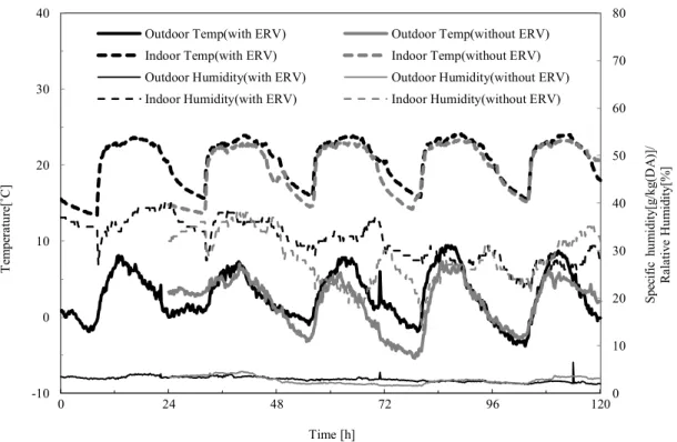
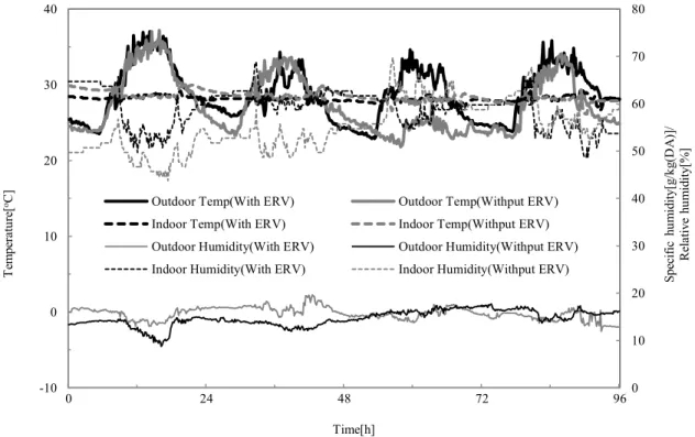
5.3.2 Impact of ERV implementation ... 103
5.3.3 CO2 demand-controlled ventilation performance ... 108
5.3.4 Heat leakage through the duct system ... 109
5.4 Discussion ... 114
5.5 Conclusions ... 116
Chapter 6 Applications 6-1.1. Introduction... 122
6-1.2 Outline of Numerical Analysis ... 124
6-1.2.1 Office model ... 124
6-1.2.2 BES-CFD integration method ... 126
6-1.2.3 BES model ... 128
6-1.2.4 CFD model ... 130
6-1.3 Outline of Field Measurement ... 131
6-1.4 Results of Numerical Simulation ... 132
6-1.4.1 Comparison with numerical prediction and field measurement ... 133
6-1.4.2 Air flow pattern and temperature distribution (CFD) ... 137
6-1.4.3 Results of time series of temperature in summer ... 140
6-1.4.5 Results of energy consumption analysis ... 142
6-1.5 Conclusions ... 143
6-2.1 Introduction ... 151
6-2.2 Methodology ... 154
6-2.2.1 Integrated BES and CFD ... 154
6-2.2.2 Carbon dioxide demand controlled ... 157
6-2.3 Application to integrated simulation ... 159
6-2.3.1 CFD model ... 159
6-2.3.2 BES model ... 162
6-2.3.3 Cases Analyzed ... 163
6-2.4. Field measurements set up ... 164
6-2.5. Validation and Discussion ... 166
6-2.5.1 Comparison of single BES with integrated BES-CFD simulation ... 167
6-2.5.2 Comparison of traditional fixed ventilation with optimized DCV ... 168
6-2.5.3 Comparison between field measurement and numerical prediction ... 179
6-2.6. Conclusion ... 183
Chapter 7 Conclusions and Recommendations 7.1 conclusions... 187
7.1.1 Dynamically predict indoor airflow properties and energy consumption ... 187
7.1.2 Evaluating integrated simulation for modeling indoor environment and comprehensive heat transfer ... 188
7.1.3 Optimized ventilation design with integration simulation ... 189
7.2 Accuracy of CFD solution ... 189
7.2.1 Differential scheme ... 189
7.2.2 Computational grid ... 190
7.2.3 Near-wall regions ... 190
7.2.4 Convergence criteria ... 190
7.3 Integrated problem and limitations ... 190
7.3.1 Time-step of integrated simulation ... 190
7.3.2 Code and compile... 191
7.3.3 Computational intense ... 191
7.4 Recommendations for future work ... 192
7.4.1 HVAC system modeling ... 192
7.4.2 Turbulence model ... 192
7.4.3 By what conditions to select an integrated simulation ... 193
7.4.4 Validation accuracy ... 193
7.4.5 Evaluate convergences ... 193
Appendix AGrid independent check ... 195
Appendix B List of Published papers... 197
Chapter 1
Introduction
1.1 General understanding of building ventilation
Building ventilation has already been emphasized as a key system with the view of creating and maintaining a sustainable and human-friendly building environment. To evaluate the ventilation system design, comprehensive issues are representatively existed, e.g. energy saving, indoor environmental quality (IEQ) and thermal comfort. IEQ has strong impacted on the environmental health, in terms of the Sick building syndrome (SBS) symptoms and infection diseases.
Meanwhile, an estimation of building energy consumption and its minimization are important challenge against the background of global environmental concern such as the global warming.
Apparently, ventilation rate is one of the key factor and its optimization in view point of energy saving and indoor environmental quality will be fundamental and critical identically. Although the quantitative impact of ventilation on infectious control in indoors remains unclear, essentially, literatures reveal attempts that being investigated in quantitative impact of ventilation on health in the indoor environment.
On the other hand, to avoid overestimating ventilation rate, CO2 demand controlled technology has been wildly used for minimizing energy consumption associated with building ventilation while maintaining an acceptable indoors in commercial and industrial buildings. The implementation of CO2 DCV in terms of energy cost saving often relates to locate climate, ventilation system features and occupant requirements.
Therefore, it is significant to provide appropriate ventilation design for various comprehensive
building and assess the system performance during all design stages. To this purpose, this thesis presents the fundamentals, implementations and application of integrated simulation as the approach to vividly reproduce the indoor environmental quality (IEQ) and energy saving potential under optimized ventilation.
1.2 Zero energy building and ventilation design
Building energy use in the Europe takes 1/3 of total energy consumption, and Architecture in China contributes 24.3%~30% of the energy energy consumption, besides, Japanese building energy use is constantly around 30% from 1965~2009. Against this background, the concept of Zero Energy Building (ZEB) has gained wide international attention during last decade and is now seen as the future target for the design of sustainable buildings. With the increasing global concern given to energy saving and greenhouse gas (GHG) emission reduction, ZEB projects are proposed and discussed worldwide as a realistic solution for the mitigation of CO2 emissions and/or the reduction of energy use in the building sector. The Energy Independence and Security Act (EISA) of 2007 adopted at the USA and the Directive on Energy Performance of Buildings (EPBD) that comes into effect in May 2010 at the European level support the goal of net zero energy and make effort internationally for all new commercial buildings by 2030. Especially, a zero-energy target for 50% reduction of the U.S. commercial buildings by 2040 and net zero for all U.S. commercial buildings by 2050 has been specified by EISA (2007). Meanwhile, the EPBD establishes the “nearly zero energy building” from 2018 for all public owned or occupied by public authorities buildings and from 2020 for entire new buildings. However, the issues with respect to developing credible and widely acceptable criteria, identifying the general type of energy balance, planning renewable energy supply option (on-site/ off-side), calculating or evaluating life cycle energy usage et al are still ambiguous.
It is widely agree that ventilation system contributes a major aspect (30%~50%) for building energy consumption, which is undertaking thermal environment by dissipating most heating or cooling load inside the buildings and ensuring better IAQ in term of removing indoor contaminants and moisture. Therefore, an appropriate ventilation design also plays an important role for ZEB global concept. To meet this sustainable idea, ventilation system studies generally regard as airflow distribution design, air diffusor performance and equipment efficiency,
1.3 Performance assessment of mechanically ventilated buildings
Providing an adequate quantity of fresh air to an occupied space is necessary for the dilution of indoor pollutant concentrations. However, using building mechanical ventilation systems for pollutant dilution is not free. Building mechanical systems use 1/3 to 1/2 of building energy consumption and a significant portion of this energy is used for conditioning outdoor air.
Accordingly, increase of the fresh air supply rate, as a single measure that reduces pollutant concentration, does not seem to be an adequate exposure prevention strategy. Therefore, dynamic building energy performance simulation is required in order to quantify potential indoor environment changes and occupants exposed to the contaminant.
In addition, ventilation effectiveness is an indicator of the quality of supply air distribution in ventilated rooms. It is a representation of how well a considered space is ventilated compared to a perfect air mixing condition. To adopt this assessment index into dynamic ventilation evaluation and thereby, to bridge the control strategy between energy cost-saving and acceptable indoor air quality is one of main advantages in this research.
1.4 Indoor Dynamic Airflow and Building Energy Simulation
Building Energy Simulation (BES), calculation of energy consumption for heating and cooling of buildings, has been adopted to the design of sustainable low energy building in recent years. The prediction of BES is based on the assumption that room air is uniform hybrid. However, this approximation is not satisfactory in stratified indoor air environment. On the contrary, computational fluid dynamics (CFD) simulation can provide more detail information such as temperature, pressure, velocity vector distribution of airflow, heat transfer and contaminant transportation indoor and outdoor building environment. Therefore, the integration of CFD and BES is important to analysis non-uniform air distribution inside enclosure zone and provide more accurate prediction of building thermal performance.
In view of employing auxiliary-control technique of ventilation system optimization, this research presents the integration simulation of BES and CFD with control algorithm of CO2
Demand Controlled Ventilation (DCV) technique applied in a typical office space to optimize the ventilation rate through energy recovery ventilator (ERV). As an approach, integration analysis of BES and CFD might be able to solve the building thermal behavior and HVAC performance in
consideration of non-uniform distributions of air flow, temperature characteristics and contaminant in the indoor space. In other word, this coupled approach has possibility to eliminate the primary assumptions, i.e. mass system and perfect mixing condition, employed in BES and provide various outputs depending on the needs of designer in order to optimize the ventilation system configuration based on non-uniformity distribution of airflow, temperature and CO2 level in indoors.
1.5 Problem statement of integrated simulation
There are three major categories along the integrated simulation development. First, to introduce the dynamics fabric model and radiation model into CFD. Since the difference of stiffness of fluid and solid, the model will be difficult to yield a convergence. In addition, the computational burden increases dramatically due to different time-scale on both fluid and solid side. Meanwhile, cumbersome code of the solvers might entirely be rewritten.
Secondly, is to develop a CFD environment into the BES. It is computationally less expensive compared with the first method as equations are solved separately avoiding the global matrixes.
But different physical models and numerical schemes of two components impose challenges in sharing and the compatibility. What’s more, one-direction coupling is not able to provide sufficient information for both energy and airflow domain. Dynamics coupling that involves frequently exchanging data also be challenged at three discontinuities in BES and CFD, time scale, space, and computing speed.
Thirdly, is to employ external integrated simulation. Pre-CFD treatment is mostly adopted as a significant step of the coupling simulation. This is requiring complicated modification of coupling controller and updating boundary conditions setting in accordance with rigorous format.
Additionally, CFD computing time grows exponentially as a function of different model size, mesh number and quality, numerical solving scheme and condition of convergence.
1.6 Research objectives and the thesis outline The objectives for this research can be summarized as:
To apply the integration simulation for estimating long term dynamic indoor airflow properties of optimizing ventilation system in terms of energy conservation and sustainable
Accurately design or reproduce hierarchical indoor thermal environment and convection heat transfer with numerical analysis solution.
Optimized controlled technologies are implemented with integration simulation in the view point of suitable and comfortable building.
This thesis started with literature review and is organized as follows:
Chapter 2 describes the development of indoor ventilation and reviews main strategies for implementation of low carbon control approach in office building. Further, integrated simulation method is introduced and being compared different coupling procedure in terms of different prediction requirements from those literatures.
Chapter 3 introduces the background and principle for the building simulation tool (TRNSYS) and CFD program (Ansys/FLUENT) respectively. Efforts are made to theoretically analyse these basic components of integrated simulation in terms of building performance and indoor airflow properties in local domain.
Chapter 4 discusses the state-of-the-art prototypes of integrated simulation. Fundamentally explain the coupling strategies and data exchanged methods of integrated simulation. In addition, the merits of coupling BES and CFD associate with indoor environment prediction and energy saving controlled in optimized ventilation design is presented.
Chapter 5 investigates the field measurement of a traditional ceiling-based HVAC system with package air conditioners and energy recovery ventilators (ERVs). And the energy cost saving and contamination control performance of a CO2 DCV system are also recorded in this real and typical Japanese office building. Testing data provide fundamental information evaluating performance of commonly used ERV and CO2 DCV systems and validate integrated simulation in the following chapter.
Chapter 6 provides two applications of optimized ventilation design. As ventilation system studies generally regard as airflow distribution design, air diffusor performance and equipment efficiency, ventilation rate regulation and passive ventilation control. This chapter thematically
demonstrate the system design and control algorithm for controlling thermal environment and adjusting ventilation rate in order to maintain IAQ with low-energy consumption.
Chapter 7 summarizes the conclusions yield from this study and provides recommendations for the future work.
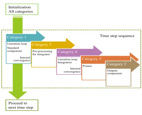
Fig.1.1 Schematic flowchart of this thesis
General statement of Mechanical ventilation system optimization Chapter 1
What is indoor ventilation for ?
Chapter 2
Conclusions and recommendations Chapter 7 Performance assessment of indoor ventilation
(energy and artificial thermal environment) Chapter 2
Fundamentals and theory of BES and CFD
Chapter 3
Integrated strategies and data exchanged
Chapter 4
simulation case study under ERV application
Chapter 6
simulation case study under CO2DCV application
Chapter 6
Monitor environmental performance under CO2DCV
T RH air movement Monitor environmental performance under ERV T RH air movement Field measurement set up
Instrument calibration Chapter 5
Integrated simulation approach
Literature review Theory
Simulation Field measurement
Chapter 2
Literature review
2.1 Introduction
In the first section, State-of-the-art of indoor ventilation systems and airflow properties evaluation criteria are presented. The literature reviews and methodologies show the fundamental and developed process of the building ventilation. For suitable and sustainable ventilation design, it is significant to understand indoor airflow distributed and contaminant removal effectiveness which are sensitive to ventilation type, system scale, diffuser position, and assessment indices.
Moreover, this chapter describes the development of integrated simulation method and attempt to compare different coupling procedure in terms of different prediction requirements from those literatures. The issue of handshaking building energy simulation (BES) and computational fluid dynamic (CFD) has been studied in various aspects, to summarize the applications in the indoor environment, this part highline the potentials of the coupling simulation in raising the prediction accuracy.
Besides the computational approaches, in addition, optimized ventilation design methods are treated as the parallel theme here. This chapter, sequentially, introduces energy recovery ventilator and carbon dioxide demanded controlled technic as main ventilation optimized process.
2.2 State-of-the-art of Indoor Ventilation
2.2.1 General descriptions of building ventilation
Building ventilation has been already systematically studied as a system since a hundred year ago (Ahrendts, 1880 and Billington 1892). It is the fact that the building ventilation directly affects the indoor air quality, which has been comprehensively explained in extensive studies (Croome 1975 and 1981). Linddament (2000) carried out a review study to show the effect of ventilation on the indoor air quality. In his study, key aspects are concerned with identifying the role of ventilation and reviewing this role in the context of the other measures that must be taken to secure a healthy indoor environment. Acceptable indoor climate can be achieved, not so much by introducing expensive concepts, but by developing a rational approach to identifying needs and applying the necessary tools to deal with each need.
Ventilation development is basically regards to improving the indoor comfort environment and reducing the health risk by infectious index patient. Since the middle of 20’s century, the global epidemic respiratory diseases break out more often than ever; e.g. Meschede smallpox (1970), measles (1985), tuberculosis (TB) (1990), SARS (2003) and H1N1 (2009), which resulted in many indoor disasters in various countries. On the other hand, following the energy crisis of the 1970’s, efforts have been made to find a balance in the controversial relationship between air distribution and indoor air quality, thermal comfort and energy efficiency in the indoor environment field (Nielsen, 2000; Awbi, 2003; Seppänen 1999 and 2008; and Melikov, 2012) in the last few decades. As people spent approximate 95% time in the indoor, concerns on perceive thermal comfort and environmental air quality are grown dramatically. However, when buildings are built more and more air-tight, indoor air quality and health issues emerge, for example the sick building syndrome (SBS). According to previous studies, the symptoms can be ameliorated with relatively high ventilation rates of 15-25 l/s per person in buildings (Seppänen 1999 and Wargocki 2012). Extensive literatures indicated the indoor air quality is sensitive not only to insufficient ventilation rate, but also due to inappropriate ventilation type. One recent study shows that mixing ventilation alone is not able to substantially reduce the exposure of medical staff to exhaled air by sick occupants when standing close (Melikov 2011).
However, various studies only report the performance of ventilation from some of these perspectives, such as ventilation efficiency, thermal comfort, IAQ and energy efficiency, and the
unclear. A recent review study shows that higher ventilation rates in offices, up to about 25 l/s per person, are associated with reduced prevalence of sick building syndrome (SBS) symptoms (Sundell, 2011). The limited data available suggest that inflammation, respiratory infections, asthma symptoms and short-term sick leave increase with lower ventilation rates. Further studies are still needed to identify the optimal solution supplying fresh air to the occupied zone or personal zone. Especially, when design a special space with a certain task in diverse climates.
Attempts and efforts are still required to reveal the quantitative impact of ventilation on health.
2.2.2 Ventilation type
Building ventilation has been classified as mixing ventilation (Robert Boyle & Son 1899), displacement ventilation (Scandinavia in 1978), personalized ventilation (Melikov 2002), hybrid air distribution (Karimipanah 2002), stratum ventilation (Lin in 2009), Local exhaust ventilation (Awbi 2011) and protected occupied-zone ventilation (Cao 2011).
Table 2.1 studies of mixing ventilation
Locations of airflow inlet and outlet
methods main focus Findings
Robert Boyle, 1899
Investigation airflow distribution and indoor air quality
This is one of the very earliest forms of mechanical ventilation
Downdraught ventilation by mechanical impulsion is pronounced by sanitarians to be highly prejudicial to health.
Clements D., 1975
Model experiment
airflow pattern and the effect of Archimedes number
The air pattern is almost a function of the Archimedes number. As Ar increases, the jet deflection from the horizontal increases.
Sandberg,
1986 Experimental
study air exchange
efficiency and contaminant exposure
The ceiling to floor system gives rise to a comparatively rapid exchange of the air with heating.
However the evacuation of the contaminant is delayed.
Nielsen’s studies, 1992
Experimental study
The effect of Archimedes number on the airflow distribution
The critical supply Archimedes number at which the jet breaks away from the surfaces as soon as it leaves the nozzle was just below 0.03.
Awbi and
Gan, 1993 Numerical
study Air distribution and ventilation effectiveness
Air distribution systems should be different for heating and cooling in order to achieve a comfortable room environment.
Outlet
Outlet Inlet
Attached plane jet Inlet
Inlet Outlet Outlet Inlet
Outlet
Inlet Outlet
Lee and
Awbi, 2004 Experimental
and numerical study
The effects of partitions on the room air quality as well as ventilation
performance
Increasing the partition gap underneath from 0%H to 10%H causes an overall improvement in the air change efficiency.
Cao et al.
2008, 2009, 2010 and 2011
Experimental
study Maximum velocity decay in the air distribution via attached plan jet
Attend plane jet can be used as an effective method to avoid draught in mixing ventilation conditions
Krajčík et al. 2012
Experimental study
Air distribution and ventilation effectiveness
The ventilation effectiveness varied between 0.4 and 1.2, where 1 is complete mixing, which depends on the position of air terminal devices.
Table 2.2 studies of displacement ventilation
Locations of airflow inlet
and outlet methods main focus Findings
Li et al.
1992 Experimental
study Temperature
profile in a room The vertical temperature profile is considerably affected by conduction through the wall and the radiant heat transfer between room surfaces, particularly between the ceiling and the floor
Awbi and Gan, 1993
Numerical study
Air distribution and ventilation effectiveness
Displacement ventilation performs better than mixing ventilation in terms of ventilation effectiveness
Awbi 1998
Experimental and numerical study
Air distribution and ventilation effectiveness
Ventilation effectiveness for thermal distribution of displacement ventilation is almost twice the value for mixing ventilation.
Lao and Chen 2007
Experimental and numerical study
Air distribution, arrangement of diffuser/extract and ventilation effectiveness
Floor-supply displacement ventilation can improve breathing zone air quality but have a higher risk of thermal discomfort.
Inlet Outlet
Inlet
Outlet Outlet Outlet
Inlet
Inlet Outlet Inlet Outlet
Outlet Inlet
Inlet Outlet
Lee and Lam, 2007
numerical
study Temperature
gradient and plume effect
The feasible zone capacity range diminished with decrease in design room temperature and/or room height.
Lee et al.
2009
Experimental and numerical study
Airflow and contaminant distributions
The air distribution effectiveness seems to be proportional to the ceiling height.
Table 2.3 studies of hybrid air distribution
Locations of airflow inlet and outlet
methods main focus Findings
Karimipanah and Awbi, et.
Al. 2007
Experimental and numerical study
Air distribution, ventilation effectiveness, air exchange effectiveness
Both experimental and CFD results confirm that the confluent jets system in most cases performed better than the displacement system regarding local air exchange efficiency and ventilation effectiveness Cho and Awbi,
2008 Experimental
and theoretical study
Air flow
distribution The wall confluent jets system produces a greater horizontal spread over the floor than displacement jet.
Awbi, 2011 Experimental
and numerical study
Air distribution efficiency, ventilation effectiveness,
Using the concept of Air Distribution Index (ADI), it is found that a confluent jets system is more efficient than displacement and mixing ventilation systems.
Inlet Outlet
Outlet
Inlet Inlet
Outlet Inlet Inlet
Outlet
Impinging jet
2.2.3 Assessment of different ventilation systems Scales of the ventilation systems
The scales of the ventilated space definitely affect the application of the ventilation system. As for the task of the personalized ventilation, the purpose is to supply fresh directly to the breathing zone. So the ventilation scale could be quite small comparing with other type of ventilation systems. However, mixing ventilation is used to dilute the indoor polluted air to keep the indoor air at a certain acceptable level, so mixing ventilation can be used for the occupied zone and for the whole space as well. A displacement ventilation system is based on the principle of displacing contaminated room air with fresh air from outside. The use of the displacement ventilation can be for specific areas of the occupied zone. Local exhaust ventilation is primarily an extract ventilation system which is very effective in rooms where localized contaminant sources can be identified, such as in industrial premises or kitchens. However, the indoor pollution sources are normally unknown in indoor environment.
Piston ventilation uses laminar flow of air distribution either vertically or horizontally across the whole room at low velocity (typically 0.2 to 0.4 m/s) and turbulence to create a “piston” type flow. Stratum ventilation has been proposed to accommodate the elevated room temperatures recommended by several governments in East Asia. However, the thermal plume produce by the human body may significantly affect the air distribution in the breathing zone. Protected ventilation is designed to protect occupants from exposure to the polluted air. Therefore, protected ventilation is suitable for the breathing zone, individual personal zone and some specific areas. Table 2.4 shows different ventilation system used for different scales.
Table 2.4 Performance of different ventilation systems with different scales
Breathing zone (BZ)/
personal zone (PZ)
Occupied zone/whole space Air supply condition Mixing
ventilation (MV)
1.2m from floor: BZ (W.K.
Chow, W.Y. Fung 1996) 1.1m from floor: BZ (M.L.
Pereira et.al 2009)
1.1m from floor: BZ (ASHRAE Standard 62)
0.075m from floor -1.8m; 0.6m to internal wall (ASHRAE Standard 62)
typically
> 1.5 m/s (Awbi, 2011)
Displacement ventilation (DV)
The overall dimensions of the mannequin were 1:725 m (standing) and 1:305 m (seated) (Awbi, 2011)
0.0/0.1 from floor -1.8m; 1.0m to the external window, doors and radiators;0.5m to external and internal walls (pr EN 13799), 0.075m from floor -1.8m; 0.6m to internal wall (ASHRAE Standard 62)
typically
< 0.5 m/s (Awbi, 2011)
Hybrid
ventilation (HV) 0.075m from floor -1.8m; 0.6m to
internal wall (ASHRAE Standard 62) > 0.25 m/s (Cho et al. 2008)
Local exhaust ventilation (LEV)
as close to the source as possible, the enclosure large enough for the source and the contaminant cloud (Health and safety Executive)
Site the work area away from doors, windows and walkways, to stop draughts interfering with the LEV and spreading the dust or vapour (Control of Substances Hazardous to Health Regulations 2002 (COSHH))
0.25-10.0 m/s, which depends on contaminant release conditions (Awbi, 2003)
Piston
ventilation (PiV) the whole room (Awbi, 2011) typically 0.2 to 0.4
m/s (Awbi, 2011) Personalized
ventilation (PV)
Moveable Panel positioned 0.2 m in front of and 0.3 m above the nose:BZ (Arsen K Melikov et.al 2002)
0.075m from floor -1.8m; 0.6m to internal wall (ASHRAE Standard 62)
0.2 – 0.6 m/s (Bolashikov, 2010)
Stratum ventilation (SV)
1.2 m above the floor: BZ ( Z.
Lin, 2009)
1.2 m/s and 5.5 ACH (Lin et al.
2011) Protective
occupant ventilation (POV)
1.50m x 1.50m x1.8m as personal working zone: PZ;
0.6-1.1m above the floor: BZ (Brohus and Nielson 1994, Bjorn et.al 1997)
comparable to MV,
>2.0 m/s
Notes: The definition of “breathing zone” from the ASHRAE standard is “the region within an occupied space between planes 3 and 72 in (75 and 1800 mm) above the floor and more than 2 ft (600 mm) from the walls or fixed air-conditioning equipment”.
2.2.4 Effectiveness and efficiency of different ventilation methods
Various types of indices for ventilation efficiency and ventilation effectiveness have been proposed and discussed since 1980. Based on different analyzed targets, e,g. airflow movement, distribution, contaminant transport, indices is classified as air change efficient, ventilation effectiveness, Heat/contaminant removal effectiveness, Exposure Effectiveness et al. Since the performance of different ventilation systems will be determined by the specific tasks, these ventilation systems could be assessed by different indices as well. These four indices that can be used to assess the performance of ventilation system, including ventilation effectiveness regarding air is change, ventilation effectiveness regarding pollutant removal, ventilation effectiveness regarding heat removal, ventilation effectiveness regarding exposure and air distribution index. Detail category is referring to Table 2.5.
Generally speaking, efficiency should be smaller or equal to 1, but effectiveness may be larger than 1, which depends on how to define the reference value for one ventilation system. As for the purpose of protective ventilation is to secure a personal occupied zone, the most important thing is to improve the performance of ventilation effectiveness regarding exposure to polluted air and local air quality. Table 2.6 matches different type of ventilation system with these assessment indices from literatures and shows a summary of ventilation effectiveness and efficiency with regard to those different ventilation systems. However, as shown in Table 2.6, index is exploited in some researches, while insufficient in others. It is difficult to compare these data directly before converting them into a uniform express or value.
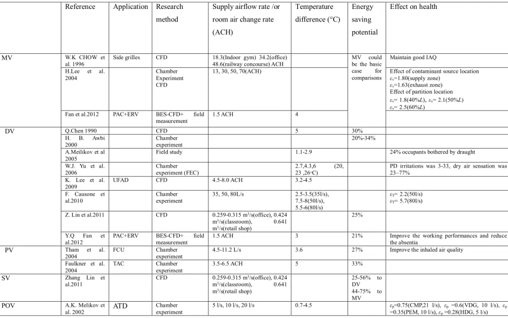
2.2.5 Energy saving potential of different ventilation systems
Table 2.7 shows the performance of different ventilation systems with regards to energy saving and IAQ. If we assume that MV could be the basic case for comparisons, then DV, PV, SV and POV have certain energy saving potential from 20% to 75%, which may depend on the temperature difference between supply temperature and room temperature. Some studies show the improvement of working performance and inhaled air quality by DV and PV, meanwhile saving about 20% energy. Most of studies only report the performance of ventilation from one of these perspectives, including efficiency, thermal comfort, IAQ and energy efficiency. Further studies are needed to identify the optimal solution supplying fresh air to the occupied zone or
Table 2.5 ventilation indices comparisons
Air exchange
ACE (Etheridge and Sandberg, 1996):
p n
a
2 nVQ
(1)
AOA (Sandberg,
1986) 0
1 (0)
P (0) CP dt
C
(2)SVE (Kato, 1988) '( )
3 ( ) s
s
SVE x C x
C Cs= q
Q (3)
Contaminati on Removal
VE (Sandberg,
1981) pi i
pt pi
a C C
C C
(4)
L-PFR (Sandberg
and Sjöberg, 1983) ( ) ( )
p p
p p
v
q V
L PFR q
C x C x dx
(5)NEV (Eunsu Lim et al 2011)
2 2
x y
NEV NEV NEV 1 1
= 1 1
x e e eff
e
y n n eff
n
NEV x u D x e
NEV y D y n
(6)
Heat removal
(Awbi and Gan
1993) P S
S R
t T T
T T
(7)
CRI (Kato et al
1994) ,
( ) ( )
/
m i m i n
m o m P
CRI c F
(8)
Air Diffusion
VER (Awbi
1993) t
R c
(9)
ADI (Awbi
2003)
c
t N
N ADI
Nt PPDt
AQ c
c PD
N
(10)
ADINew Awbi
(2011)
c
p n t New
ADI S
1 3 (11)
Table 2.6 Assessment of different ventilation system with different index
Tasks Index Ventilation
Air exchange Pollutant removal Heat removal Exposure to
contaminant
Airflow Distribution
a ACH e VE a(%) t(%) p ADPI ADI
MV 0.42-0.35
(A.
Novoselac, J.
Srebric 2003) (Eq. 1)
4-6 ACH (ASHRAE 62 2010)
0.4-1.0 (5ᴼC<ΔT<0ᴼC);
0.9-1.0 (0ᴼC<ΔT<-5ᴼC) (Olesen, 2012) (Eq. 1) 0.6-0.72 (circular supply and rectangular exhaust)
0.75-0.86 (rectangular supply and exhaust)
1.14-1.2(circular supply and exhaust) (Michal Krajčík et.al 2012)
1.12-1.63 (wall grill supply, ACH 1-7) (Potter, 1988) (Eq. 4)
0.8-1.0 (ASHRAE Standard 62)
0.42-1.42 (Awbi, 1993) 50 (Mundt, 1994)
99 (T.
Karimipanah,.
Awbi,2008) (Eq. 7)
60%-90%
(ASHRAE Standard 55)
a range of effective draft temperatures of -3° to +2° of average room temperature at a coincident air velocity less than 70 fpm (Eq. 9)
15.5(T.
Karimipanah, H.B.
Awbi,2008) (Eq. 10)
DV 0.55-0.92(A.
Novoselac, J.
Srebric 2003) (Eq. 1)
4ACH (ASHRAE 170)
p0.9-1 (top-return) 0.9-1.3 (floor-return) (Chao CY Wan MP, 2004)
0.2-1.4 (2<ΔT<0 ) (Olesen, 2012) (Eq. 1)
1.2 (ASHRAE Standard 62.1-2007)
1.15 (normal) 1.05-1.25(L-UFAD) 1.05(H-UFAD) ( Kisup Lee Q. Chen 2009)
60-70 (Nielsen (1993)
121(T.
Karimipanah , Awbi,2008) (Eq. 7)
15.9(T.
Karimipanah, and Awbi,2008) (Eq. 10)
HV, LEV and PiV
1 for PiV (A.
Novoselac, J.
Srebric 2003) (Eq. 1)
0.5-4 ACH for HV (IEA Annex 35)
2 for PiV (ASHRAE draft Standard 62 1989R) (ASHRAE 1996)
1.24-1.44 for LEV (ACH 1-7) (Potter, 1988) (Eq. 4)
123 for HV (T.
Karimipanah, Awbi,2008) (Eq. 7)
15.7-16.1 for HV (T.
Karimipanah, Awbi, 2008) (Eq. 10)
PV 1.2-2.2 (ΔT=-6ᴼC)
1.3-2.3 (ΔT=-3ᴼC) 1.6-3.5 (ΔT=-0ᴼC)
1.35-2.38(Arsen K Melikov et.al 2002) 1.3-1.9 (D Faulkner et.al 1999)
65-90 (Bauman FS et al.
8%-35% (4 l/s 26ᴼC)
50%-75%(6 l/s 26ᴼC)
80%-95 (8 l/s 26ᴼC)
2006) (Kumar et al. 2008)
100% (0.3-0.35 m/s) (Melikov 2004)
0.26-0.58 (Arsen K Melikov et.al 2002)
SV 1.58-1.98)
( Z. Lin, 2011)
1.42-1.50(25.5 < design temperature<
27 °C)( Tian et. al, 2011)
Eq. 4
>80% (air velocity <
0.8 m/s, EDTS −1.2-1.2) ( Z.Lin, 2011) (Eq.
9)
Table 2.7 Performance of different air distribution methods with regards to energy saving and IAQ
Reference Application Research method
Supply airflow rate /or room air change rate (ACH)
Temperature difference (°C)
Energy saving potential
Effect on health
MV W.K CHOW et
al. 1996
Side grilles CFD 18.3(Indoor gym) 34.2(office) 48.6(railway concourse) ACH
MV could be the basic case for comparisons
Maintain good IAQ H.Lee et al.
2004
Chamber Experiment CFD
13, 30, 50, 70(ACH) Effect of contaminant source location
εv=1.80(supply zone) εv=1.63(exhaust zone) Effect of partition location εv=1.8(40%L), εv=2.1(50%L) εv=2.5(60%L)
Fan et al.2012 PAC+ERV BES-CFD+ field measurement
1.5 ACH 4
DV Q.Chen 1990 CFD 5 30%
H. B. Awbi
2000 Chamber
experiment 20%-34%
A.Meilikov et al 2005
Field study 1.1-2.9 24% occupants bothered by draught
W.J. Yu et al.
2006
Chamber experiment (FEC)
2.7,4.3,6 (20, 23 ,26°C)
PD irritations was 3-33, dry air sensation was 23–77%
K. Lee et al.
2009 UFAD CFD 4.5-8.0 ACH 3.2-4.5
F. Causone et al.2010
Chamber experiment
35, 50, 80L/s 2.5-3.5(35l/s), 7.5-8(50l/s), 5.5-6(80l/s)
εT=2.2(50l/s)
εT=5.7(80l/s) Z. Lin et al.2011 CFD 0.259-0.315 m3/s(office), 0.424
m3/s(classroom), 0.641 m3/s(retail shop)
25%
Y.Q Fan et al.2012
PAC+ERV BES-CFD+ field measurement
1.5 ACH 3 21% Improve the working performances and reduce
the absentia
PV Tham et al.
2004 FCU Chamber
experiment 4.5-11.2 L/s 3.6 27% Improve the inhaled air quality
Faulkner et al.
2004
TAC Chamber
experiment
3.5-6.5 ACH 5 33%
SV Zhang Lin et
al.2011
CFD 0.259-0.315 m3/s(office), 0.424 m3/s(classroom), 0.641 m3/s(retail shop)
25-56% to DV 44-75% to
2.3 Literature review on integration of BES-CFD 2.3.1 Integration between BES and CFD
Integration of BES tools with CFD has been investigated for the indoor air climate with different degrees of complexity (Negrao, 1995; Nielson, 1999; Hensen 1999;
Beausoleil-Morrison, 2000; Zhai, 2002; Djunaedy, 2005; Trcka, 2006; Mirsadeghi, 2009). Contemporarily, introducing simple approach where BES and CFD interact without direct incorporated into each other, CFD has been applied into the BES program to predict indoor airflow properties distribution, e.g. air movement, temperature and concentration in indoor climate. Chen (1988) integrated an energy simulation component that solves radiative and convective heat transfer into CFD program for comprehensive heat transfer analysis in buildings. In this approach, energy and indoor air characteristics predicted simultaneously and computing costs were effectively reduced compared with a conjugated CFD program. Nielsen (1999) provided thorough review of capability of interconnection between CFD and BES to estimate the thermal comfort and air quality of target space in a building. With limited consideration, essentially, CFD boundary condition lacked of thermal storage effect of building envelope, external transient meteorological effect and interactions with building services. He confirmed that an interconnection between a CFD program and a building energy performance simulation program would improve both the energy consumption data and the prediction of thermal comfort and air quality in a selected area of a building.
Hensen (1999) distinguished coupling simulation on the basic of conflation frequency between BES and CFD which is representing as uni-directional (one-way) or bi-directional (two-way) coupling. In cases where bi-directional coupling was adopted, he defined several coupling strategies to exchange variables on time step bases. Onion
coupling was corresponding to fully-dynamic coupling (Zhai 2003) or strong coupling (struler et al 2000), which required an iteration procedure to ascertain user defined convergence criteria. Ping-pong coupling was compliance with Quasi-dynamic (Zhai 2003) or loose coupling (struler et al 2000), where coupled simulators use the predicted coupling data without iteration on a time step basis. Srebric et al. (2000) optimized airflow-and-energy coupling simulation, as a preliminary investigation, for building heating capacity calculation and indoor airflow, thermal comfort distribution evaluations.
For the viewpoint of integration, CFD module and BES components environment are developed to solve building performance and indoor environment interactively and accurately. As hard coupling, all variables were solved simultaneously to achieve convergence, and it was including the thermal characteristics and processes in the walls into the model so that the boundary condition of the CFD can be moved from the inside to the outside of the wall which is capturing the dynamics of the external conditions.
Sequentially, loose internal coupling indicated two separate analysis processes that are calculated for solid and flow field via parameters exchange in predefined way without rewriting the code. Computationally expensive is reduced since whole equations do not need to solve synchronously. External coupling simulation was proposed as a master program coordinates the process, multi-airflow properties can capture the dynamics numerical simulation. Due to runtime external coupling, the existing numerical packages for specific geometrical or physical domains work together and exchange data at predefined or calculated time-steps. It has been recognized and justified that the final distributed simulation environment is more flexible, practical, and powerful than the sum of the individual software programs.