Highly Efficient and Stable Perovskite Solar Cells via Modification of Energy Levels at the Perovskite/Carbon Electrode Interface
Author Zhifang Wu, Zonghao Liu, Zhanhao Hu, Zafer Hawash, Longbin Qiu, Yan Jiang, Luis K. Ono, Yabing Qi
journal or
publication title
Advanced Materials
volume 31
number 11
page range 1804284
year 2019‑01‑24
Publisher WILEY‑VCH Verlag GmbH & Co. KGaA, Weinheim Rights (C) 2019 The Author(s).
Author's flag publisher
URL http://id.nii.ac.jp/1394/00000918/
doi: info:doi/10.1002/adma.201804284
Creative Commons Attribution‑NonCommercial‑NoDerivatives 4.0 International
www.advmat.de
Highly Efficient and Stable Perovskite Solar Cells via Modification of Energy Levels at the Perovskite/Carbon Electrode Interface
Zhifang Wu, Zonghao Liu, Zhanhao Hu, Zafer Hawash, Longbin Qiu, Yan Jiang, Luis K. Ono, and Yabing Qi*
Dr. Z. Wu, Dr. Z. Liu, Dr. Z. Hu, Dr. Z. Hawash, Dr. L. Qiu, Dr. Y. Jiang, Dr. L. K. Ono, Prof. Y. B. Qi
Energy Materials and Surface Sciences Unit (EMSSU) Okinawa Institute of Science and Technology Graduate University (OIST)
1919-1 Tancha, Onna-son, Kunigami-gun, Okinawa 904-0495, Japan E-mail: [email protected]
The ORCID identification number(s) for the author(s) of this article can be found under https://doi.org/10.1002/adma.201804284.
DOI: 10.1002/adma.201804284
perovskites to ambient exposure,[5] thermal stress,[6]and other factors[7] hamper the commercialization and practical applica- tions of PSCs.[8] Thus, it is urgent to develop stable PSCs with long-term stability.
In terms of the evaluation of long-term stability of silicon solar cells, the standard- ized stability accelerated test according to the International Electrotechnical Commis- sion (IEC) 61215 is usually used. In this standard test, a solar cell is placed under damp heat testing (85 °C, 85% relative humidity) to track its device performance.
Recently, Bush et al. reported that the encap- sulated perovskite/silicon tandem cell with sputtered ITO is able to pass the damp heat test under 85 °C and 85% relative humidity (double 85 aging condition).[9] However, few works have demonstrated stable PSCs without encapsulation under such harsh testing conditions. A number of factors (e.g., light, temperature, and moisture) can affect the stability of unencapsulated perovskite solar cells under such rigorous double 85 aging conditions.[10] In this regard, it is desirable to develop stable perovskite solar cells consisting of the components that are stable under double 85 aging condition.
It is reported that MA is more sensitive to thermal stress compared to FA.[11] Thus, the removal of MA from the perov- skite absorber is an effective strategy to solve the intrinsic thermal instability issue of perovskite. In terms of the top con- ductive electrode, the carbon electrode is a good candidate to solve the instability issue induced by moisture because of its hydrophobic property. This advantage enables the carbon elec- trode to efficiently protect the perovskite layer from moisture, thus enhancing stability of PSCs.[12] Meanwhile, cost of carbon is significantly lower than that of commonly used gold or silver electrode. In addition, its favorable compatibility with printing methods, such as screen-printing and doctor blading, avoids the usage of vacuum evaporation.[12b] These motivations have inspired us to adopt the architecture of FTO/TiO2/perovskite/
carbon to develop efficient and stable PSCs. However, perov- skite solar cells with carbon electrodes usually suffer from the problem of energy level mismatch at the perovskite/carbon inter- face, where the work function (WF) of carbon is substantially lower than the ionization energy (IE) of perovskite. Mismatch of energy level alignment between perovskite and carbon limits the resultant device performance.[13] A polymer interlayer is widely used to adjust interface properties, especially energy Perovskite solar cells (PSCs) have attracted great attention in the past few
years due to their rapid increase in efficiency and low-cost fabrication. How- ever, instability against thermal stress and humidity is a big issue hindering their commercialization and practical applications. Here, by combining thermally stable formamidinium–cesium-based perovskite and a moisture- resistant carbon electrode, successful fabrication of stable PSCs is reported, which maintain on average 77% of the initial value after being aged for 192 h under conditions of 85 °C and 85% relative humidity (the “double 85” aging condition) without encapsulation. However, the mismatch of energy levels at the interface between the perovskite and the carbon electrode limits charge collection and leads to poor device performance. To address this issue, a thin- layer of poly(ethylene oxide) (PEO) is introduced to achieve improved inter- facial energy level alignment, which is verified by ultraviolet photoemission spectro scopy measurements. Indeed as a result, power conversion efficiency increases from 12.2% to 14.9% after suitable energy level modification by intentionally introducing a thin layer of PEO at the perovskite/carbon interface.
Solar Cell Stability
Metal halide perovskite solar cells (PSCs) have attracted great attention in the past few years due to their rapid increase of effi- ciency from the initial 3.8%[1] to the current record of 22.7%.[2]
Perovskite materials with the typical structure of ABX3 (A = FA, MA or Cs) show various advantages, such as high optical absorp- tion coefficients,[3] small exciton binding energy,[4] and long charge carrier diffusion lengths,[4] which all contributed to the high efficiency comparable to commercialized silicon solar cells. However, the instability issues caused by the sensitivity of
© 2019 The Authors. Published by WILEY-VCH Verlag GmbH & Co.
KGaA, Weinheim. This is an open access article under the terms of the Creative Commons Attribution-NonCommercial-NoDerivs License, which permits use and distribution in any medium, provided the original work is properly cited, the use is non-commercial and no modifications or adaptations are made.
The copyright line for this article was changed on 25 April 2019 after original online publication.
www.advmat.de www.advancedsciencenews.com
level alignment, in optoelectronic devices.[14] In this work, poly- (ethylene oxide) (PEO) is employed for the first time to modify the perovskite/carbon interface, improving energy level alignment between perovskite and carbon. Combining more thermally stable FACs-based organic–inorganic hybrid perovskite with humidity- resistant carbon electrodes, we successfully fabricate stable organic–inorganic hybrid PSCs for the first time, which remain on average of 77% of the initial value after being aged for 192 h under double 85 aging condition even without encapsulation.
Here, the control perovskite films (Pero) is deposited by the two-step interdiffusion method.[15] the PEO-modified perovskite (Pero/PEO) is fabricated by spin-coating the PEO/isopropanol (IPA) solution on the top of perovskite films, followed by thermal annealing to remove the solvent. As shown in Figure S1 of the Supporting Information, the structure of perovskite is characterized by X-ray diffraction (XRD). The diffraction peaks for the alloyed perovskite at 14.02°, 19.93°, 24.46°, 28.25°, 31.73°, 40.39°, and 42.94° are assigned to the (111), (112), (021), (222), (231), (240), and (333) crystal planes, while the peaks at 26.40°, 37.76°, 51.50° are assigned to the FTO substrate.
No peaks at 12.6° (PbI2) and 11.7° (yellow phase FAPbI3) are found, indicating the high-quality and phase-purity of our FA–
Cs-based perovskites.
Furthermore, we carried out X-ray photoelectron spectro- scopy (XPS) measurements to investigate the surface composi- tion of our alloyed perovskite film. The two peaks at the binding energies (BEs) of 143.47 and 138.54 eV shown in Figure S2 of the Supporting Information can be assigned to Pb-4f5/2 and Pb-4f7/2. The peaks at 630.93 and 619.41 eV correspond to I-3d3/2 and I-3d5/2, respectively. In the case of the C-1s core level, the perovskite film shows two main peaks at 288.48 and 284.80 eV, respectively.[16] The higher BE component is assigned to the C-1s core-level of FA while the lower BE component is attributed to remaining solvent or other unavoidable contami- nation from air exposure.[17] The peak with a binding energy of 400.61 eV comes from N-1s core-level of FA.[16] We fitted the XPS spectra to quantify the surface perovskite composition after normalization using atomic sensitivity factors provided by Kratos company. The determined surface composition based on the XPS results is FA0.48Cs0.20PbI2.27Br0.25. The determined element ratio of Cs to Pb at the surface is ≈20%, which agrees well with the element ratio in the precursor solution (20%). The determined ratio of Br to I is ≈11%. The loss of organic cation and halide are possibly due to the formation of PbI2 during the annealing process. In addition, XPS is a surface sensitive char- acterization technique with a penetration depth typically less than 10 nm, which can only provide the surface chemical com- position instead of bulk.[18] Because of: (i) phase-segregation phenomena, (ii) temperature-induced release of organic compo- nents in perovskite starting from the surface, and (iii) the pos- sible different surface stoichiometry with respect to the bulk film,[6b] it is important to characterize the bulk chemical compo- sition of the film.[19] As a result, while the trace amount of PbI2 is able to be detected by surface sensitive XPS measurements, it is below the detection limit of XRD measurements.
To determine the bulk composition of the film, we performed X-ray fluorescence (XRF) measurements. The reference samples of CsI and PbBr2 were prepared and measured by XRF for cal- ibration purposes. XRF measurements on our FA-Cs perovskite
film yields a ratio of Br to Pb of ≈38%. Due to the overlapping of the Cs and I peaks (Figure S3a, Supporting Information), we used two methods to evaluate the ratio of Cs to I. In the first method, we fitted the raw spectra with Gaussian-shaped peaks using the method of least squares,[19] and the determined ratio of Cs to I was ≈7.2%. In the second method, we first calculated the ratio of (Cs+I) to (Pb+Br). The nonvolatile property of Cs and the Cs/Pb element ratio of precursor solution was consid- ered. On the basis of the XPS results, we assumed that the ratio of Cs to Pb is 20% (Table S1, Supporting Information), which matched well the nominal concentration. The determined ratio of Cs to I was ≈6.9%, which is good agreement with the results derived from the first method. The determined ratio of Br to I was ≈13.6%, consistent with the results derived from XPS measurement. Based on the XPS, XRF, and XRD data, the bulk composition of our alloyed perovskite film is determined to be FA0.8Cs0.2PbI2.64Br0.36 (Table S2, Supporting Information).
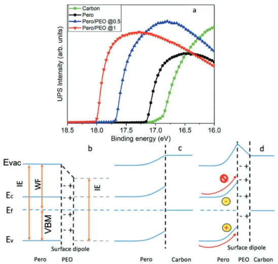
To investigate the influence of PEO modification on the energy levels of perovskite film, we performed ultra- violet photoemission spectroscopy (UPS) measurements.
As shown in Figure 1a, the WF of FA0.8Cs0.2PbI2.64Br0.36 perovskite is determined to be 4.08 eV. Its valence band maximum (VBM) is determined to be located at 1.65 eV below the Femi level, yielding an ionization energy of 5.73 eV.[20] The WF of carbon used here is determined to be 4.37 eV. The observed large mismatch of energy level align- ment (1.36 eV) can have a negative effect on the solar cell performance.[21] After PEO modification, WF of Pero/PEO decreases from 4.08 to 3.52/3.21 eV for the 0.5/1 mg mL−1 cases, respectively, as indicated in Figure 1. We proposed the surface dipole formation on the basis of the observation that the WF of the perovskite film decreased after PEO modification.
Meanwhile, the VBM of the perovskite remains unchanged and is located at 1.65 eV (Figure S4, Supporting Information) and the corresponding IE reduces from 5.73 to 5.17/4.86 eV, respectively.[20] Note that although IE is an intrinsic property of a material and usually a constant, here the IE values are obtained for the perovskite film mixed with PEO. As a result, the energy offset between valence band of the perovskite and the WF of the carbon changes from 1.36 to 0.80 and 0.49 eV in the cases of 0.5 and 1 mg mL−1, respectively. This reduction of energy level mismatch is expected to improve charge collection and therefore lead to higher device performance.
The energy level alignment determined by UPS is shown in Figure 1b. Schottky barrier formation is due to the dif- ference of WF of two materials after these two materials are brought to contact. Spontaneous band bending can take place due to the difference of WF between the carbon and perov- skite.[22] In our study, the PEO modification further increases the difference between the WF values. As a result, a more upward band bending takes place. This upward band bending not only facilitates hole extraction but also helps block electron transfer from perovskite to carbon. The more-upward band bending here is expected to contribute to improved device performance.[18]
The other consideration is the interfacial charge accumula- tion due to the contact doping that may also lead to the band bending.[23] To address this question, we investigated the role of PEO thickness in the WF and VBM of the perovskite
film by UPS. Figure S5 of the Supporting Information shows the WF of the perovskite gradually decreases while the VBM remains unchanged upon increasing the PEO thickness.
Doping not only affects the WF but also affects the VBM. In our study, the VBMs remain unchanged, thus doping effects can be excluded. On the basis of WF and VBM analysis above,
the band bending observed in our studies seems to be sup- ported by the interfacial dipole phenomena.
XPS is used to confirm the existence of PEO on the top of the perovskite/PEO mixed film. As shown in Figure 2, the peak with a binding energy (BE) of 531.92 eV can be assigned to the O-1s core level, which may come from the residue IPA or unavoidable Figure 1. a) UPS spectra (He−Iα = 21.22 eV) of the secondary electron cutoff region of the carbon electrode sample, perovskite control sample, and PEO-modified perovskite sample. b) Schematic illustration of the energy level diagram of the perovskite film after PEO modification. c) Perovskite/carbon.
d) Perovskite/PEO/carbon. Note that here the IE value for the PEO-modified perovskite sample is obtained for the perovskite film mixed with PEO.
Figure 2. XPS spectra (Al−Kα = 1486.6 eV) of the Pb-4f and O-1s core levels of perovskite samples modified with different PEO concentrations:
a) 1 mg mL−1, b) 0.5 mg mL−1, and c) PEO free.
www.advmat.de www.advancedsciencenews.com
air exposure. The peak located at 533.25 eV is assigned to the O-1s core level originating from PEO. Two main peaks located at BEs of 143.59 and 138.70 eV, are assigned to Pb-4f5/2 and 4f7/2 core levels, respectively. Interestingly, a negligible amount of Pb0 is observed when PEO (0.5 mg mL−1) is coated on top of perovskite. When further increasing the concentration of PEO to 1 mg mL−1, an obvious Pb0 peak is observed. It is reported that Pb0 functions as defect states, causing nonradiative recom- bination.[24] Although the energy offset between perovskite and carbon is more suitable for perovskite modified with 1 mg mL−1 PEO compared to the one with 0.5 mg mL−1, a high concentra- tion of PEO may have an adverse impact on cell performance due to the presence of a large amount of Pb0 component.
Thus, we will use the perovskite films modified with PEO of 0.5 mg mL−1 for further studies.
To check whether the reduced energy barrier between the VBM of the perovskite and the WF of the carbon benefits hole extraction, we performed time-resolved photoluminescence (TRPL) measurements. We included two exponential functions in our model shown below to fit the curves, where τi refers to time constant of exponential component, Ai denotes the frac- tional amplitude for each exponential[25]
exp exp
PL 1
1 2
I A t A t 2
τ τ
( ) ( )
= − + − (1)
τav referring to the amplitude-weighted average lifetimes can be given by the equation below[25,26]
A A
av 1 1 2 2
τ = × +τ ×τ (2)
Fractional contribution (fi) of each decay time to the whole time can be calculated by the following equation[25]
f A
i Ai i
j j
∑
j ττ= ×
× (3)
The TRPL spectrum is composed of a fast and a slow-decay component.[27] The long decay component τ2 was attributed to radiative recombination of free carriers, which was mainly associated with charge transfer processes across the inter- face. The fast-decay component was assigned to trap-assisted nonradiative recombination at the interface.[27a] As shown in Table S3 of the Supporting Information, τ1 of the Pero sample is determined to be 2.41 ns according to the fitting, and τ1 of the perovskite(Pero)/PEO sample is determined to be 8.57 ns, both of which are still within the same order of magnitude.[27c]
Also, the fitting shows that the τ2 values of the two samples are almost the same. Taking Ai into consideration, the amplitude- weighted average lifetimes corresponding to the respective slow decay or fast decay are almost the same. The fitted τav of TRPL for the two kinds of samples of Pero and Pero/carbon (Figure 3;
Table S3, Supporting Information) are similar and consistent with the lifetime derived from the time when the PL intensity decreases to 1/e of the initial intensity. The fractional contribu- tion (f1) of fast decay to the whole time are almost the same as shown in Table S3 of the Supporting Information. Based on these results, the interfacial trap does not change after PEO surface modification. In the case of perovskite coated with
carbon (Pero/carbon), the decrease of A2× τ2 dominantly con- tributes to the reduction of lifetime. The PL quenches faster for the Pero/PEO/carbon sample than the Pero/carbon sample indicating the faster charge transfer between perovskite and carbon, which can be attributed to the better matching of the energy level alignments between perovskite and the carbon electrode.
The steady-state PL is measured to evaluate the photo- luminescence quantum yield (PLQY). Figure S6 of the Sup- porting Information shows that the post-treatment with PEO results in little impact on the PL intensity. PLQY values of 9.3%
and 4.3% were estimated for the perovskite film, respectively.
The much faster quenched PL for the Pero/PEO/carbon sample suggests that charge transfer between perovskite and carbon is largely enhanced after PEO modification, which can be attributed to the better match of the energy level alignment between perov- skite and the carbon electrode.[13,28]
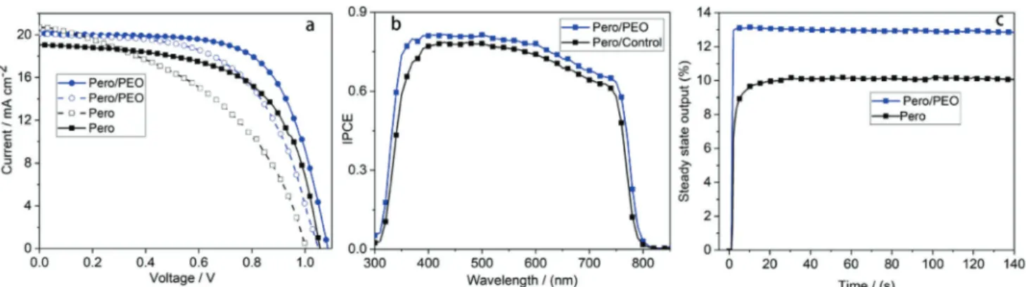
To study the impact of PEO modification on the cell per- formance, we fabricated PSCs using FA0.8Cs0.2PbI2.64Br0.36 as light absorber with the configuration of FTO/compact-TiO2/ meso-TiO2/perovskite/carbon (Figure S7 and Table S4, Sup- porting Information). The control cell (i.e., without PEO) with an active area of 0.1 cm2 shows a power conversion efficiency (PCE) of 12.2%, open-circuit voltage (Voc) of 1.06 V, short- circuit current (Jsc) of 19.0 mA cm−2, and fill factor (FF) of 60.1% (Figure 4a, and Table 1). After PEO modification, the cell shows a PCE of 14.5%, Voc of 1.08 V, Jsc of 20.1 mA cm−2, and FF of 66.4% in the reverse scan (Voc → Jsc) of the cur- rent–voltage (I–V) curve. The corresponding device perfor- mance parameters under forward scan (Jsc→ Voc) are 12.3%, 1.05 V, 20.1 mA cm−2 and 58.5%. As shown in Figure S8 of the Supporting Information, the champion PEO-modified cell shows a Voc of 1.08 V, a Jsc of 21.2 mA cm−2, a FF of 64.7%, and an impressive efficiency of 14.9%. Figure 4b shows internal photon-to-current efficiency (IPCE) spectra of two kinds of cells, the larger IPCE value for the PEO-modified cell is con- sistent with the higher JSC obtained in I–V measurements.
This observation can also be attributed to the better matched Figure 3. TRPL spectra of perovskite samples with/without carbon and with/without PEO modification.
energy level alignment and improved hole extraction from perovskite to carbon electrode. Figure 4c shows the steady-state output of the two cells. It is observed that steady-state output PCE increase from 10.1% to 13.0% after PEO modification, which is consistent with the above I–V measurements. In addition, the much faster rise up of steady output for the PEO- modified cell indicates the much faster charge collection in this device. This observation is in good agreement with better matched energy level alignment.[17]
To further investigate the impact of PEO modification on the charge carrier behavior in devices under working condition, we further performed electrochemical impedance measurements under light illumination. Figure S9a of the Supporting Informa- tion shows the Nyquist plots of cells with and without PEO mod- ification under light illumination at a bias of 0.2 V. The Nyquist plots of the devices show three main features: an obvious arc in the high frequency region attributed to the charge transfer pro- cess at the perovskite/carbon counter electrode interface;[12,29]
a small middle frequency feature and obvious low frequency feature attributed to electrode polarization[30] or ion behavior in the device[31] By fitting the Nyquist plots with equivalent circuit shown in Figure S9a of the Supporting Information, we can obtain the charge transfer resistance for the devices at given bias. It is found that PEO-modified device shows much lower charge transfer resistance than that of control device. This result confirms a much better charge collection in PEO modi- fied cell, which is consistent with TRPL and stabilized output results. These results further prove that modu lating energy levels alignment between perovskite and carbon electrode with PEO modification can reduce charge transfer barrier between perovskite and carbon, leading to efficient hole extraction and improved device performance.
The stability of perovskite solar cells is affected by many factors such as phase segregation, interface ion diffusion or environment condition. Light-induced halide segregation may lead to the structure instability in the case of mixed halide perovskite.[32] To evaluate the phase stability of the mixed halide perovskite in our study, we tracked the XRD evolution under the continuous 1 sun illumination and low humidity (relative humidity of ≈5%) As shown in Figure S10 of the Supporting Information. After 192 h continuous light soaking, we did not observe any peak splitting, shifts or emergence of new peaks, indicating that our mixed halide perovskite possesses high phase stability under light illumination.
Use of carbon as the back electrode has been demonstrated as an effective strategy to prolong solar cell lifetime.[33] To solve the instability issues caused by environmental factors such as temperature and humidity, we combine the temperature- insensitive FA–Cs perovskite and humidity-resistant carbon electrode. To demonstrate that solar cells using carbon-based electrodes are resilient to humidity, we tracked the stability of solar cells with the device configuration of FTO/TiO2/Pero (FA–
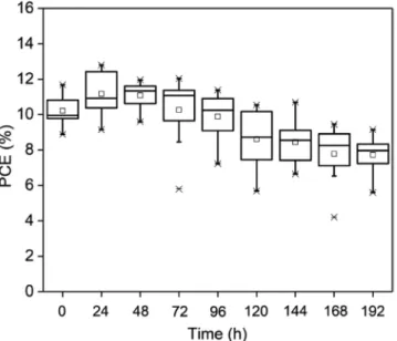
Cs) /spiro/Au marked with FA–Cs/spiro/Au. Figure S12 of the Supporting Information shows that 15 FA–Cs/spiro/Au cells completely decomposes and exhibits less than 1% of the initial PCE after being aged for 120 h under 85% humidity and room temperature. While the PCE of 8 FA–Cs/carbon cells keeps an average of 77% of the starting efficiency even after being aged for 192 h under the temperature of 85 °C and relative humidity (RH) of 85% (i.e., “double 85” condition) as shown in Figure 5. The champion cell keeps 91% of the initial performance (Figure S11, Supporting Information). This result clearly demonstrates that the solar cells with carbon electrode shows outstanding stability against the humidity. To show the advantage of FA–Cs-based perovskite, which is more robust at elevated temperatures com- pared with the MA-based perovskite, we tracked the PCE evolu- tion of solar cells with the device configuration of FTO/TiO2/Pero (MAPbI3)/carbon marked with MA/carbon. Figure S12 of the Supporting Information shows that 14 MA/carbon cells retain only 2% of staring PCE after being aged for 120 h under 85 °C and ambient humidity (relative humidity of ≈45%). While PCE of 8 FA–Cs/carbon based cells keep on average 77% of the initial efficiency even under double 85 °C/85% conditions. These two results clearly show that the solar cells based on FA–Cs/carbon perovskite film exhibit superior stability against high temperature Figure 4. a) Current–voltage (I–V) curves of the carbon-based perovskite solar cells with and without PEO modification (solid line: reverse scan, dashed line: forward scan). b) IPCE curve and c) steady-state output curve of the carbon-based perovskite solar cells with and without PEO modification.
Table 1. Photovoltaic parameter of cells based on pure carbon electrode.
PSCs Scan
direction Voc [V]
Jsc [mA cm−2]
FF [%]
Efficiency [%]
Stead-state output [%]
Pero/PEO Reverse 1.08 20.1 66.4 14.5 13.0
Forward 1.05 20.1 58.5 12.3
Pero/control Reverse 1.06 19.0 60.1 12.2 10.1
Forward 1.00 20.8 44.5 9.3
www.advmat.de www.advancedsciencenews.com
and humidity. We further tracked the stability of solar cells based on FA–Cs perovskite film and carbon electrode under double 85 condition and 1 sun light illumination. Figure S12 of the Supporting Information shows that our FA–Cs and carbon based cells only keep average 19% of the starting PCE.
These new results suggest the aging condition of 1 sun illumi- nation and double 85 °C/85% is still challenging for our solar cells using the FA–Cs perovskite film and carbon electrode, and more efforts are needed to achieve high stability under such a harsh condition.
To investigate whether the suppression of interface ion migration possibly improves the stability of perovskite solar cells, we contacted our FA–Cs-based perovskite with silver elec- trode in the presence and absence of PEO and monitor the I species by XPS. The penetration depth of XPS is about 10 nm and the thickness of Ag electrode is 70 nm. Figure S13 of the Supporting Information shows that both two samples show I element, indicating that the PEO does not contribute to the suppression of interface ion migration. Based on this observa- tion, we conclude that the interfacial ion migration does not help to improve the stability.
In conclusion, we introduced a thin-layer of PEO to modify the perovskite/carbon interface, and successfully modulated the energy level alignment between FACs-based perovskite and carbon electrode to achieve efficient charge transfer. As a result, PEO-modified cells show a 22% increase of energy conversion efficiency compared to the cells without modification, and deliver an impressive energy conversion efficiency of 14.9% and stabi- lized efficiency of 13.0% under AM 1.5G conditions. Moreover, taking advantage of more thermally stable FA0.8Cs0.2PbI2.64Br0.36 perovskite and moisture-resistant carbon electrode, our PEO modified PSCs keep on average 77% of their initial PCEs after being stored for 192 h under double 85 aging condition without encapsulation. Our work provides an effective approach to achieving stable and efficient PSCs overcoming double 85 issue toward commercialization and practical applications.
Supporting Information
Supporting Information is available from the Wiley Online Library or from the author.
Acknowledgements
This work was supported by funding from the Energy Materials and Surface Sciences Unit of the Okinawa Institute of Science and Technology Graduate University, the OIST R&D Cluster Research Program, the OIST Proof of Concept (POC) Program, and JSPS KAKENHI (Grant No.
JP18K05266).
Conflict of Interest
The authors declare no conflict of interest.
Keywords
carbon electrode, energy level alignment, perovskite solar cells, poly(ethylene oxide), stability
Received: July 6, 2018 Revised: November 22, 2018 Published online: January 24, 2019
[1] A. Kojima, K. Teshima, Y. Shirai, T. Miyasaka, J. Am. Chem. Soc.
2009, 131, 6050.
[2] https://www.nrel.gov/pv/assets/images/efficiency-chart.png (accessed: March 2018).
[3] J. Burschka, N. Pellet, S. J. Moon, R. Humphry-Baker, P. Gao, M. K. Nazeeruddin, M. Gratzel, Nature 2013, 499, 316.
[4] S. D. Stranks, G. E. Eperon, G. Grancini, C. Menelaou, M. J. P. Alcocer, T. Leijtens, L. M. Herz, A. Petrozza, H. J. Snaith, Science 2013, 342, 341.
[5] a) R. Adharsh, Y. Kai, A. K.-Y. Jen, Adv. Mater 2018, 30, 1800455;
b) Z. Hawash, L. K. Ono, S. R. Raga, M. V. Lee, Y. B. Qi, Chem.
Mater. 2015, 27, 562; c) M.-H. Li, H.-H. Yeh, Y. H. Chiang, U. Jeng, C.-J. Su, H.-W. Shiu, Y.-J. Hsu, N. Kosugi, T. Ohigashi, Y.-A. Chen, P.-S. Shen, P. Chen, T.-F. Guo, Adv. Mater 2018, 30, 1801401.
[6] a) E. J. Juarez-Perez, Z. Hawash, S. R. Raga, L. K. Ono, Y. B. Qi, Energy Environ. Sci. 2016, 9, 3406; b) E. J. Juarez-Perez, L. K. Ono, M. Maeda, Y. Jiang, Z. Hawash, Y. B. Qi, J. Mater. Chem. A 2018, 6, 9604; c) J. Cao, X. Lv, P. Zhang, T. T. Chuong, B. Wu, X. Feng, C. Shan, J. Liu, Y. Tang, Adv. Mater. 2018, 30, 1800568.
[7] a) S. Wang, Y. Jiang, E. J. Juarez-Perez, L. K. Ono, Y. B. Qi, Nat. Energy 2017, 2, 16195; b) W. Li, W. Zhang, S. Van Reenen, R. J. Sutton, J. Fan, A. A. Haghighirad, M. B. Johnston, L. Wang, H. J. Snaith, Energy Environ. Sci. 2016, 9, 490.
[8] a) L. Qiu, L. K. Ono, Y. B. Qi, Mater. Today Energy 2018, 7, 169;
b) L. K. Ono, Y. B. Qi, J. Phys. D:Appl. Phys. 2018, 51, 27.
[9] K. A. Bush, A. F. Palmstrom, Z. J. Yu, M. Boccard, R. Cheacharoen, J. P. Mailoa, D. P. McMeekin, R. L. Z. Hoye, C. D. Bailie, T. Leijtens, I. M. Peters, M. C. Minichetti, N. Rolston, R. Prasanna, S. Sofia, D. Harwood, W. Ma, F. Moghadam, H. J. Snaith, T. Buonassisi, Z. C. Holman, S. F. Bent, M. D. McGehee, Nat. Energy 2017, 2, 17009.
[10] T. A. Berhe, W.-N. Su, C.-H. Chen, C.-J. Pan, J.-H. Cheng, H.-M. Chen, M.-C. Tsai, L.-Y. Chen, A. A. Dubale, B.-J. Hwang, Energy Environ. Sci. 2016, 9, 323.
Figure 5. The evolution of device performance from the stability test of eight PEO-modified perovskite solar cells based on carbon electrode without encapsulation under 85 °C and 85% RH without light soaking.
[11] a) J. W. Lee, D. H. Kim, H. S. Kim, S. W. Seo, S. M. Cho, N.-G. Park, Adv. Energy Mater. 2015, 5, 1501310; b) W. Qiu, A. Ray, M. Jaysankar, T. Merckx, J. P. Bastos, D. Cheyns, R. Gehlhaar, J. Poortmans, P. Heremans, Adv. Funct. Mater. 2017, 27, 1700920.
[12] a) X. Xu, Z. Liu, Z. Zuo, M. Zhang, Z. Zhao, Y. Shen, H. Zhou, Q. Chen, Y. Yang, M. Wang, Nano Lett. 2015, 15, 2402; b) A. Mei, X. Li, L. Liu, Z. Ku, T. Liu, Y. Rong, M. Xu, M. Hu, J. Chen, Y. Yang, M. Grätzel, H. Han, Science 2014, 345, 295; c) Z. Liu, M. Zhang, X. Xu, L. Bu, W. Zhang, W. Li, Z. Zhao, M. Wang, Y.-B. Cheng, H. He, Dalton Trans. 2015, 44, 3967; d) Z. Ku, Y. Rong, M. Xu, T. Liu, H. Han, Sci. Rep. 2013, 3, 3132.
[13] X. Zheng, H. Chen, Q. Li, Y. Yang, Z. Wei, Y. Bai, Y. Qiu, D. Zhou, K. S. Wong, S. Yang, Nano Lett. 2017, 17, 2496.
[14] a) Y. Zhou, C. Fuentes-Hernandez, J. Shim, J. Meyer, A. J. Giordano, H. Li, P. Winget, T. Papadopoulos, H. Cheun, J. Kim, M. Fenoll, A. Dindar, W. Haske, E. Najafabadi, T. M. Khan, H. Sojoudi, S. Barlow, S. Graham, J. L. Bredas, S. R. Marder, A. Kahn, B. Kippelen, Science 2012, 336, 327; b) X. Liu, Y. Wang, F. Xie, X. Yang, L. Han, ACS Energy Lett. 2018, 3, 1116;
c) C.-C. Chueh, C.-Z. Li, A. K. Y. Jen, Energy Environ. Sci. 2015, 8, 1160.
[15] Q. Jiang, L. Zhang, H. Wang, X. Yang, J. Meng, H. Liu, Z. Yin, J. Wu, X. Zhang, J. You, Nat. Energy 2016, 1, 16177.
[16] B. Philippe, M. Saliba, J.-P. Correa-Baena, U. B. Cappel, S.-H. Turren-Cruz, M. Grätzel, A. Hagfeldt, H. Rensmo, Chem. Mater. 2017, 29, 3589.
[17] Z. Hawash, S. R. Raga, D.-Y. Son, L. K. Ono, N.-G. Park, Y. B. Qi, J. Phys. Chem. Lett. 2017, 8, 3947.
[18] H. Hantsche, Scanning 1989, 11, 257.
[19] Y. Jiang, M. R. Leyden, L. Qiu, S. Wang, L. K. Ono, Z. Wu, E. J. Juarez-Perez, Y. B. Qi, Adv. Funct. Mater. 2018, 28, 1703835.
[20] a) P. R. Brown, D. Kim, R. R. Lunt, N. Zhao, M. G. Bawendi, J. C. Grossman, V. Bulovic´, ACS Nano 2014, 8, 5863;
b) C.-H. M. Chuang, P. R. Brown, V. Bulovic´, M. G. Bawendi, Nat.
Mater. 2014, 13, 796; c) D. M. Kroupa, M. Vörös, N. P. Brawand, B. W. McNichols, E. M. Miller, J. Gu, A. J. Nozik, A. Sellinger, G. Galli, M. C. Beard, Nat. Commun. 2017, 8, 15257.
[21] H. Chen, S. Yang, Adv. Mater. 2017, 29, 1603994.
[22] a) W.-Q. Wu, Q. Wang, Y. Fang, Y. Shao, S. Tang, Y. Deng, H. Lu, Y. Liu, T. Li, Z. Yang, A. Gruverman, J. Huang, Nat. Commun. 2018,
9, 1625; b) J. Lu, X. Lin, X. Jiao, T. Gengenbach, A. D. Scully, L. Jiang, B. Tan, J. Sun, B. Li, N. Pai, U. Bach, A. N. Simonov, Y.-B. Cheng, Energy. Environ. Sci. 2018, 11, 1880.
[23] S. Wang, T. Sakurai, W. Wen, Y. B. Qi, Adv. Mater. Interfaces 2018, 5, 1800260.
[24] W. Zhang, S. Pathak, N. Sakai, T. Stergiopoulos, P. K. Nayak, N. K. Noel, A. A. Haghighirad, V. M. Burlakov, D. W. deQuilettes, A. Sadhanala, W. Li, L. Wang, D. S. Ginger, R. H. Friend, H. J. Snaith, Nat. Commun. 2015, 6, 10030.
[25] J. R. Lakowicz, Principles of Fluorescence Spectroscopy, Springer, Berlin 2010.
[26] Y. K. Eom, I. T. Choi, S. H. Kang, J. Lee, J. Kim, M. J. Ju, H. K. Kim, Adv. Energy Mater. 2015, 5, 1500300.
[27] a) H. Xi, S. Tang, X. Ma, J. Chang, D. Chen, Z. Lin, P. Zhong, H. Wang, C. Zhang, ACS Omega 2017, 2, 326; b) D.-Y. Son, J.-W. Lee, Y. J. Choi, I.-H. Jang, S. Lee, P. J. Yoo, H. Shin, N. Ahn, M. Choi, D. Kim, N.-G. Park, Nat. Energy 2016, 1, 16081; c) Q. Chen, H. Zhou, T.-B. Song, S. Luo, Z. Hong, H.-S. Duan, L. Dou, Y. Liu, Y. Yang, Nano Lett. 2014, 14, 4158.
[28] Z. Liu, Q. Chen, Z. Hong, H. Zhou, X. Xu, N. De Marco, P. Sun, Z. Zhao, Y.-B. Cheng, Y. Yang, ACS Appl. Mater. Interfaces 2016, 8, 11076.
[29] a) Z. Yu, B. Chen, P. Liu, C. Wang, C. Bu, N. Cheng, S. Bai, Y. Yan, X. Zhao, Adv. Funct. Mater. 2016, 16, 4866; b) H. Chen, Z. Wei, H. He, X. Zheng, K. S. Wong, S. Yang, Adv. Energy Mater. 2016, 6, 1502087.
[30] H.-S. Kim, N.-G. Park, J. Phys. Chem. Lett. 2014, 5, 2927.
[31] a) A. Dualeh, T. Moehl, N. Tétreault, J. Teuscher, P. Gao, M. K. Nazeeruddin, M. Grätzel, ACS Nano 2014, 8, 362;
b) E. Guillén, F. J. Ramos, J. A. Anta, S. Ahmad, J. Phys. Chem. C 2014, 118, 22913.
[32] M. C. Brennan, S. Draguta, P. V. Kamat, M. Kuno, ACS Energy Lett.
2018, 3, 204.
[33] a) X. Li, M. Tschumi, H. Han, S. S. Babkair, R. A. Alzubaydi, A. A. Ansari, S. S. Habib, M. K. Nazeeruddin, S. M. Zakeeruddin, M. Grätzel, Energy Technol. 2015, 3, 551; b) Y. Rong, Y. Hu, A. Mei, H. Tan, M. I. Saidaminov, S. I. Seok, M. D. McGehee, E. H. Sargent, H. Han, Science 2018, 361, eaat8235.