10-1
E
Directional Control V
alves
9 Solenoid voltage (See page E10-2)
10 Allowable T port back pressure 7: 20.6 MPa
11 Port orifice (option)
Omit: no port orifices (standard) Port orifices
<Example 1> P08 (0.8 mm orifice in P port) Orifice diameter Port (A, B, P and T)
<Example 2> B12 (1.2 mm orifice in B port) <Example 3> 2 port combinations
Combination sequence, PTAB P10T12, P08B10
12 Design no.
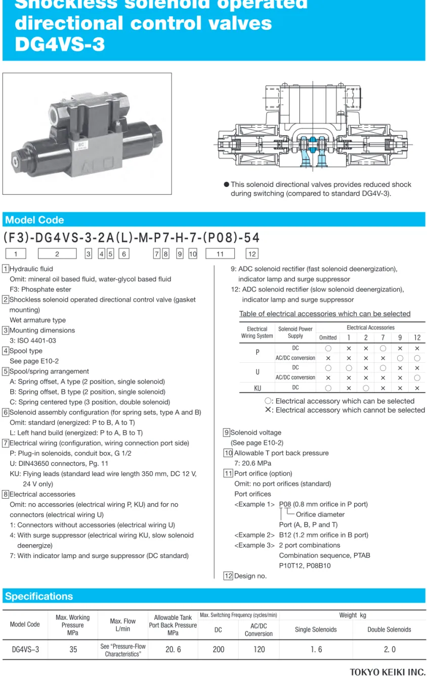
●This solenoid directional valves provides reduced shock during switching (compared to standard DG4V-3).
1 Hydraulic fluid
Omit: mineral oil based fluid, water-glycol based fluid F3: Phosphate ester
2 Shockless solenoid operated directional control valve (gasket mounting)
Wet armature type 3 Mounting dimensions
3: ISO 4401-03 4 Spool type
See page E10-2
5 Spool/spring arrangement
A: Spring offset, A type (2 position, single solenoid) B: Spring offset, B type (2 position, single solenoid) C: Spring centered type (3 position, double solenoid)
6 Solenoid assembly configuration (for spring sets, type A and B) Omit: standard (energized: P to B, A to T)
L: Left hand build (energized: P to A, B to T)
7 Electrical wiring (configuration, wiring connection port side) P: Plug-in solenoids, conduit box, G 1/2
U: DIN43650 connectors, Pg. 11
KU: Flying leads (standard lead wire length 350 mm, DC 12 V, 24 V only)
8 Electrical accessories
Omit: no accessories (electrical wiring P, KU) and for no connectors (electrical wiring U)
1: Connectors without accessories (electrical wiring U) 4: With surge suppressor (electrical wiring KU, slow solenoid
deenergize)
7: With indicator lamp and surge suppressor (DC standard)
9: ADC solenoid rectifier (fast solenoid deenergization), indicator lamp and surge suppressor
12: ADC solenoid rectifier (slow solenoid deenergization), indicator lamp and surge suppressor
Specifications
(F3)-DG4VS-3-2A(L)-M-P7-H-7-(P08)-54
1 2 3 4 5 6 7 8 9 10 11 12Model Code
直 流 交 直変 換 シングルソレノイド ダブルソレノイド DG4VS-3 35 圧力・流量特性参照 20.6 200 120 1.6 2.0 最大切換頻度 (回/分) 質 量 kg 形 式 最 高使用圧力 MPa タンクポ-ト 許容背圧 MPa 最大流量 L/min 無記号 1 2 7 9 12 直流 ○ × × ○ × × 交直変換 × × × × ○ ○ 直流 ○ ○ × ○ × × 交直変換 × × × × × ○ KU 直流 ○ × ○ × × × U 電気アクセサリ P 電気配線 方式 ソレノイド 電源Table of electrical accessories which can be selected
○: Electrical accessory which can be selected
×
: Electrical accessory which cannot be selectedElectrical
Wiring System Solenoid Power Supply DC DC AC/DC conversion AC/DC conversion DC Electrical Accessories Omitted
Model Code Max. Working Pressure MPa
Allowable Tank Port Back Pressure
MPa DC ConversionAC/DC Single Solenoids Double Solenoids
Max. Switching Frequency (cycles/min) Weight kg Max. Flow
L/min See “Pressure-Flow
Characteristics”
Shockless solenoid operated
directional control valves
E
10-2
Directional Control V
alves
Spool Types and Pressure-Flow Characteristics
Solenoid Specifications
3位置 P A Bポートブロック P B ブロックAポート スプリングオフセットA形 スプール 2位置 スプリング センタ形 形式記号・図記号 最大流量 L/min 7MPa 14MPa 21MPa 28MPa 35MPa 7MPa 14MPa 21MPa 28MPa 35MPa 7MPa 14MPa 21MPa 28MPa 35MPa P T A B B A T P B A T P B A T P B A 形 式 中 立 時- C -
- B -
- BL -
直流、交直変換ソレノイド(印加電圧は定格の90%)
3
8
31
0
2
6
80 80
80
45 45 45 30 25
45 45 45 30 25
80 80 80
80 80 80
45 45
80
80
80
80
45 30 25
80
(45)(45)(38)(33)(30)
80 80 80
80 80 80
80 80
80
45 30 23 19
45 30 23 19
65 35 30
30 23 18 14
65 35 28 24
52 42
60 38 27 23
60 38 27 23
65 35 30
65 35 28 24
30 23 18 14
60 50
60
50
60
50
80 80 80 80 80 80
DG4VS-3-0C DG4VS-3-2C b P T B A a b P T B A a DG4VS-3-3C DG4VS-3-6C b P T B A a b P T B A a DG4VS-3-8C DG4VS-3-31C b P T B A a a P T B A b DG4VS-3-0B DG4VS-3-0BL DG4VS-3-2B DG4VS-3-2BL A B P T b A B P T b a T P A B a T P A B DG4VS-3-3B DG4VS-3-3BL DG4VS-3-6B DG4VS-3-6BL A B P T b A B P T b a T P A B a T P A B DG4VS-3-8B DG4VS-3-8BL DG4VS-3-31B DG4VS-3-31BL A B P T b A B P T a b T P A B a T P A B P B P B P A P A Bポート ブロック ブロック ブロック Bポート ブロック Aポート Aポート スプリングオフセットA形 スプール 形式記号・図記号 2位置 最大流量 L/minN,A,AL
N,A
AL
N,A
AL
P T A B B A 7MPa 14MPa21MPa28MPa35MPa 7MPa 14MPa21MPa28MPa35MPa 7MPa 14MPa21MPa28MPa35MPa 切 換 過 渡 期 形 式- A -
- AL -
注)・スプール形式8の( )内の数値はA,Bポートを閉としたときの最大流量です。 ・最大流量とは弁の切換えに支障を生じない限界の流量です。50 15 10 10 10
80 80 80 63 60
80 40 26 22 20
2
a T P A B DG4VS-3-2AL b A B P T DG4VS-3-2A ・KU4コイルの場合、本表と異なることがあります。 電 源 電圧記号 電圧V 周波数Hz 保持電流A 消費電力W 許容電圧変 動 幅 % 絶縁等級 許容 温度 G 12 2.36 29 H 24 1.16 28 R 100 0.29 29 TR 0.33 30 BR 0.29 29 VR 0.17 31 直流 (DC) 交流 ↓ 直流 (交直変換) (ADC) ±10 H 種 (180℃) ±10 H 種 (180℃) ― AC 100 V 50/60 Hz ↓ DC 90 V (コイル) AC 200 V 50/60 Hz ↓ DC 180 V (コイル) AC 110 V 50/60 Hz ↓ DC 100 V (コイル)Note: • Current values and power consumption varies with temperature conditions. Values shown in table are based on 30°C.
• In the AC/DC conversion type, AC power is used to activate the DC solenoid by the built-in rectifier, and it comes with the characteristics featured by DC solenoids. This means that the items given for the DC solenoids apply for the maximum flow.
• Consult Tokyo Keiki for details on solenoids for the supply voltages which are not listed above.
Power Supply
DC
Voltage
Code VoltageV FrequencyHz
Holding Current A Power Consumption W Allowable Voltage Fluctuation % H (180ºC) H (180ºC) (coil) (coil) (coil) AC DC (AC/DC conversion) (ADC) Insulation Class Allowable Temperature Spool Center Position 3 Position
Spring Centered Spring Offset, B Type
Model Code, Functional Symbol Max. Flow L/min B port
block A port block 2 Position
DC, AC-DC Rectifier Solenoid (applied voltage 90% of rated)
Note: • Values in ( ) for spool type 8 are max. flows with A, B ports blocked. • Max. flow refers to limit flow without valve malfunction for valve switching. • For KU4 coil, it may differ from this table.
Spool Transient Condition
Model Code, Functional Symbol Max. Flow L/min 2 Position
Spring Offset, A Type
B port
10-3
E
Directional Control V
alves
Characteristics Curve
Pressure Drop Characteristics
Pressure drop characteristics are the same as DG4V-3 (see page E2-8).
Switching Times
Notes on Operation
●Mounting orientation
No restrictions on valve mounting attitude. ●Solenoid energization
Always ensure that one side of solenoid is deenergized before energizing the opposite side. For spring centered and spring offset valves, solenoid should be continuously energized during circuit switching. Deenergization of solenoid will cause spool to return to prescribed position by spring force. ●T (tank) port piping
Prevent abnormal pressure surges above the allowable back pressure rating from being generated in T port. Valve is wet armature type so ensure that valve is always filled with oil. ●Using valves as two-way and three-way
Valve is designed as four-way and max. flow is limited when using as two or three-way valves. Consult Tokyo Keiki for details.
●Long periods of solenoid energization
Care should be paid as long periods of solenoid energization at high pressure may cause spool sticking and switching malfunction.
●Malfunctions due to surge pressure
Avoid combining flows of tank lines prone to surge pressures. Surge pressures in T port may lead to spool malfunctions. ●Manual operation
For manual switching, push the manual override pin. Be aware that actuation force increases with higher back pressure. (See graph)
●Solenoid indicator lamp
For valves with indicator lamps, the lamps will light when current flows to the solenoid.
●Electrical wiring
Solenoid and conduit box are pre-wired. Refer to below diagrams for wiring from power source to conduit box and DIN connectors. 電気信号 回路圧力 OFF ON b P T a B A 50 100 150 200 0 1 2 3 4 5
Back Pressure MPa
Actuation Force
N
Spring centered, spring offset types
P type 3 2 1 U type (DIN connector) 2 1 3 3 2 2 1 1 Common connection Ground terminal (M3)
4-M3 screw (terminal strip width 7.6 mm)
SOL b. SOL a. SOL. 3-terminal screw (M3) 1 2 3 Plug-in method of connection. Connected by DIN connector 電 源 動 作 消磁時間 スプリングオフセット形 スプリングセンタ形 C,B,BL スプリング オフセット形 A,AL 励 磁 スプリング リタ-ン 励 磁 早い 遅い 交直変換 整流器 内 蔵 スプリングリタ-ン 単位:ms 直 流 40 120 30 80 80
The electrical wiring has no polarities.
Terminals 1 and 2 have no polarities.
T A B P 0 47 74 ●Mounting dimensions 6 19 168. 7 25 325 3175 266 163 075 0 . . . . . 40 5. 27 8 10 3 . . 4-M5, 14 deep . 4- ø7.5 (max.) 表面粗さ 0.01以下 0.01 (□100mm当り) □100 寸 法 許容差 取付ボルトねじ穴:±0.1 ポート穴:±0.2 平面度 1.6μm Ra
●Mounting surface machining accuracy
Conditions: No. 2 spool, open loop circuit, flow 40 L/min, supply pressure 17.5 MPa, fluid viscosity 20 mm2/s
Note: • Values shown may vary according to spool type and circuit conditions.
[Circuit Example] [Switching Time Definition] Unit: ms Electrical signal Circuit pressure Power Supply DC with Rectifier AC/DC conversion Operation Spring Return Spring Return Fast Slow Energize Energize De-energize Time Spring Offset
Spring Centered Spring Offset
Surface Roughness
Flatness Less than 0.01 ( per 100 mm)
Mounting bolt hole: ±0.1 Ports: ±0.2
Permissible Tolerance
E
10-4
Directional Control V
alves
Dimensions
Spring Centered DG4VS-3-*C-M-P* 74 37 52 104 76 92 31 47 38 4- ø5.6 hole ø9.5 counterbore depth 405. . 32 5. . 24 5. T port 2-indicator lamp A port P port B port 168 7 3Wiring connection port 2-G1/2
Manual override pin (both ends) 49 525.
Screwed plug at other end
675. 209 Space required for coil removal Solenoid b 8C type solenoid a Solenoid a 8C type solenoid b DIN43650 connector Wiring connection port Pg.11 Applicable cable diameter ø6 to 9
DG4VS-3-*C-M-KU* DG4VS-3-*C-M-U*
.
Lead wire AVX wire (0.85 mm2)
60 5 A port T port B port P port 209 209 . 39 53 53 39 80 92 5 350+30 0 . 125 A port T port B port P port (dashed line) (solid line) DG4VS-3-*A/B-M-P* DG4VS-3-*AL/BL-M-P* 11 1525. Spring Offset Spring Offset Solenoid b 8BL type solenoid a Solenoid a 8B type solenoid b
10-5
E
Directional Control V
alves
Mounting Bolts (JIS B 1176, Strength Class 12.9)
●Mounting bolts must be ordered separately. ●Tightening torque of mounting bolts: 7 to 8 N•m
Subplate
●Subplate and bolts must be ordered separately. ●See page R6-6 for dimensions.
●See page R6-6 for plural mount subplates.
●Max. working pressure is 21 MPa. For higher pressures, valve should be mounted on manifold block.
O-ring
Construction
Solenoid coil (P type)
六角穴付きボルト 本 数 M5×50 4 A/B C 2 008001817 JIS B 2401 1A-P20 1 2 4 008000217 JIS B 2401 1A-P4 2 4 5 007902617 AS568-026(NBR,Hs70) 1 2 7 007911429 AS568-114(FKM,Hs90) 1 2 12 007901219 AS568-012(NBR,Hs90) 4 4 14 007911419 AS568-114(NBR,Hs90) 1 ― 23 007900817 AS568-008(NBR,Hs70) 1 1 個 数 照号 部品番号 規 格 -1 5 2 - 5 14 1-1 2-1 3-1 4-1 6-1 7-1 8-1 9-1 10-1 9-1 10-1 2 - 9 2 - 10 2 - 8 2 - 7 2 - 6 2 - 3 2 - 4 2 - 1 2 - 2 12 15 11 13 23 22 21 20 19 16 17 18 P形 A形 B形 C形 接続口径 Rc 側面配管用 DGMS-3-1E-10-T-JA-J 裏面配管用 DGVM-3-10-T-JA-J 3/8 サブプレ-ト形式 照号 電圧記号 部品番号 G 40078304 H 40078305 R 40078307 TR 40078308 BR 40078307 VR 40078309 3
Hex Socket Bolts
Subplate
Qty Connection Port Dia.
Rc Side Piping Bottom Piping P type A type B type C type No.
No. Voltage Code Part No.