STUDY OF ELECTRICAL AND DIELECTRIC PROPERTIES OF DIELECTRIC BARRIER DISCHARGES (DBD)
GENERATED BY SILICON DIODE FOR ALTERNATING CURRENT (SIDAC) IN WATER
著者 チュオン ティ ホア
著者別表示 Truong Thi Hoa journal or
publication title
博士論文要旨Abstract 学位授与番号 13301甲第4826号
学位名 博士(学術)
学位授与年月日 2018‑09‑26
URL http://hdl.handle.net/2297/00053073
doi: 10.1063/1.4984947
Creative Commons : 表示 ‑ 非営利 ‑ 改変禁止 http://creativecommons.org/licenses/by‑nc‑nd/3.0/deed.ja
Dissertation
STUDY OF ELECTRICAL AND DIELECTRIC PROPERTIES OF DIELECTRIC BARRIER DISCHARGES (DBD)
GENERATED BY SILICON DIODE FOR ALTERNATING CURRENT (SIDAC) IN WATER
双方向性トリガーダイオードを用い生成した水中の誘電体バリア放電における電気と誘電特 性に関する研究
Kanazawa University
Graduate school of Natural Science and Technology Electrical Engineering and Computer Science
(Abstract)
Student ID No. 1524042010
Author TRUONG THI HOA
Chief advisor: Prof. Yoshihiko Uesugi Date of Submission Sep, 2018
Abstract
In this study, DBD plasmas in water were investigated as a sequence of a bubble formation and an electronic process within the bubbles. The gas bubbles are simply produced at initial stage by gas flow through microsize glass holes. Silicon diode for alternating currents (SIDAC) has been used to generate high voltage pulses with tens of kilovolt derivation, as the bubble formed, an electrical breakdown instantaneously takes place within the bubble. The generation of such DBD plasma should be analyzed sufficiently when its characteristics are governed by two switches: the SIDAC switching characteristic and the dielectric layers.
Additionally, this work also focused on design, construction, and optimization of configuration of a novel high voltage pulse power source for large-scale dielectric barrier discharge (DBD) generation by using a device called Silicon Diodes for Alternating Current (SIDAC) and the self-terminated characteristic of DBD without external controlling. The DC power supply has been designed in a simple modular structure, non-control requirement, the transformer elimination, minimum number of levels in voltage conversion required to achieve the desired operating condition leading to a reduction in size, weight, simple maintenance and high scalability of the DBD generator.
1
1 Properties of DBD generation in bubble in water by using Silicon Diodes for Alternating Current (SIDAC)
The electrical characteristic of DBD generation in bubble in water by using Silicon Diodes for Alternating Current (SIDAC) have been investigated in comparison with one in gas phase. In both cases, the utilization of SIDAC has offered an alternating less expensive power source for generating DBD plasmas. The SIDAC switching characteristic as a slow switch ignites DBD and self-termination characteristic of DBD as a fast switch turns SIDACs off.
1.1 Experimental setup and condition
The experimental setups for DBD plasma in gas phase and in bubbles in water are shown in Figure 1, and 2, respectively, and condition is shown in Table 1. In this setup, the circuit is composed of 10 SIDACs (K1V38(W)) connected to a step-up transformer (KTS-1KEDF 110/6600) and a conventional AC power supply (PCM-500).
In gas phase, the planar reactor is 300 mm × 100 mm × 1 mm of the Tempax plates placed in parallel at a gap of 2 mm. The electrodes are 20 mm2 copper tape.
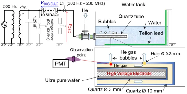
In water, a copper rod is located inside a tiny inner quartz tube that is filled by ultra-pure water in order to prevent breakdown inside the tube. This rod works as a high voltage electrode.
These are located concentrically inside an outer quartz tube. There is a number of holes with size of 0.3 mm in diameter on the wall of this outer tube. When Helium as working gas is blown into water through these holes, a number of bubbles are formed. A wire with PTFE insulator is set on the bottom of a water tank. This PTFE wire and water work as grounded electrode. In this configuration, whole DBD reactor is submerged under tap water, the discharge gap is the gas area between inner tube and outer tube and inside the bubbles surrounded by water.
2
Figure 1 Experimental setup of DBD generation in gas phase
Figure 2 Experimental setup of DBD generation in bubbles in water Table 1. Experimental condition
Primary voltage 100 V
Frequency 500 Hz
Power supply PCR-500M
Transformer KTS-1KEDF
Transformer ratio 110/6600
Working gas He (1 L/min)
Pressure Atmospheric pressure
3 1.2 Results and discussion
a) b)
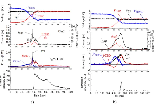
Figure 3 A typical enlargement waveform of DBD discharge using SIDAC, DBD generation in gas phase (a), DBD generation in bubbles in water (b)
The experimental result is illustrated in Figure 3. Once, the SIDACs switch on, the voltage on the DBD reactor (vDBD) changes sharply with dvDBD/dt up to 20 kV/μsec , a discharge occurs, a conducting channel is established from high voltage electrode to grounded electrode of water.
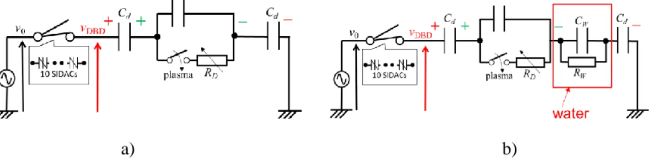
It can be seen from Figure 3, the discharge progress in both cases is similar. The current in the circuit is included displacement current caused by the change of voltage on the reactor and discharge current caused by the movement of free charges during discharge duration. The deposition of charged particle on the dielectric surface reduces the electric field in the gap spacing and then leads to the extinguishing of the discharge, as a sequence, current is gradually eliminated and less than the holding current of SIDACs, thus SIDACs are turned off. In comparison with the case of discharges in gas phase, the displacement currents, powers consumption in case of discharge in water are much higher. In case of DBD in gas phase, the peaks of currents (iDBD) are about 1.2 A, while in case of DBD in water, the peaks of current (iDBD) are approximately 1.5 A. The difference is mainly due to the high relative permittivity and conductivity of water represented as Cw and Rw inequivalent circuit (Figure 4).
4
a) b)
Figure 4 Equivalent circuit of DBD reactor, in gas phase (a), in water (b) 1.3 Active species in the plasma
The emission from plasma is relevant to present of active species in the DBD. In this study, these species were identified by Optical Emission Spectroscopy (OES) method using a broad band spectrometer (Ocean Optic 2000+, 200 - 1100 nm, 2048 pixels) (Figure 5a). The emission spectra is shown in Figure 5b. The emission spectra from plasma reveals the present of important active species (OH, O) and sterilizing agent (UV light) along with Ozone (O3), and Hydroxyl peroxide (H2O2) in the DBD product.
a) b)
Figure 5 Emission spectra of the DBD plasma generated in 0.02 slm O2 and 5slm He mixture gas, measurement setup (a), and result (b)
1.4 Effect on Methylene blue (MB) (a model pollutant) decomposition
The efficiency of the discharge for water purification has been estimated by decomposing Methylene blue (MB) dissolved in water. Different observations have been done by increasing
5
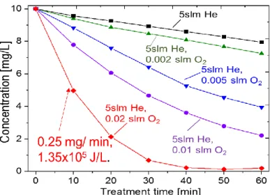
Figure 6 Time evolution of MB concentration treated by DBD plasmas
the small amount of Oxygen gas added to Helium working gas. Then, time evolution of MB concentration in MB aqueous solution treated by these DBD plasmas obtained is shown in Figure 6.Without Oxygen gas added, degradation process seems to be linear, while increasing O2 flow rate added to supply gas, the plasma treatment process tends to be an exponential process. The highest decomposition rate has been obtained by using a gas mixture of 0.02 slm Oxygen and 5slm Helium. The treatment speed is about 0.25 mg/ min with input energy density of 1.35x10⁵ J/L.
2 Novel design of high voltage pulse source for efficient DBD plasma generation by using SIDAC
The dielectric layers in configuration of DBD reactor make this discharge characterized as a capacitive load, self-terminated discharge. Therefore, DBD generation requires a high frequency alternating voltage source or a high frequency repetitive pulse power source. There is a variety of power supply types used for DBD generation depending on the different applications. However, the requirement of the expensive and complex power source configurations that could make DBD installation become expensive and selective. In this work, a compact DC power supply has been designed based on the high-speed switching characteristic of (SIDAC) and the self-termination characteristic of DBD. This DC power supply can be flexibly powered by a commercial DC power supply, or a battery, or DC output of a photovoltaic system. Because of direct connection to output of a photovoltaic panel, it could provide a promising solution for application of DBD the area without power grid connection.
6 2.1 Modular structure of the DC power supply
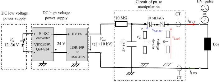
The high voltage pulse source has been designed in modular structure. The output of each module is connected in series (Figure 7). The first module is named as DC low voltage supply can be employed with flexibility by different types of power sources such as a commercial DC power supply powered by power grid, or a battery, or a DC output of an independent photovoltaic system. The second module was named as DC high voltage power supply that is responsible for stepping up the DC voltages supplied by the first module before feeding the circuit of pulse manipulation. The third module was named as module of circuit of pulse manipulation that is responsible for high voltage pulse generation.
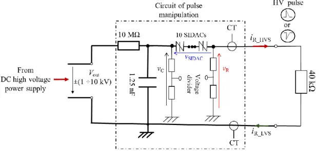
Figure 7 Modular structure of high voltage pulse source 2.2 Testing performance with a load of resistor
The performance of the pulse power source was experimentally tested with a load of 40 kΩ resistor. The diagram of circuit connection is shown inFigure 8, and experimental results are demonstrated inFigure 9. In this figure, the typical waveforms of voltage on the capacitor (vC), applied voltage to the series connection of SIDACs (vSIDAC), voltage on the resistor (vR), currents measured at high voltage side (iR_HVS) and low voltage side (iR_LVS) of resistor are shown. Before switching, SIDACs are in nonconductive state, the load is electrically isolated from power supply, then the voltage on resistor is nearly equal to zero, the voltage on the connection of SIDACs is nearly equal to the voltage on charge capacitor (vC). The voltage (vC) is gradually charged up to the breakover voltage of SIDACs, of about 4 kV, the SIDACs are
7
Figure 8 Diagram of circuit connection of experiment testing with a resistor load
(a) (b)
Figure 9 Results of experiment with a resistor, waveforms around conductive state of SIDAC (a), and enlargement waveforms around positive current peaks (b)
8
switched on to be conductive, the rapid transition of SIDACs’ state simultaneously provides high voltage pulse applied to load of the resistor. During this transient state, the voltage on capacitor and the current flow through the circuit are reduced exponentially (Figure 9 a). When the current through the SIDACs is smaller than their holding current of 50 mA. The SIDACs are switched off and turned to blocking state. The load of resistor and the charge capacitor are electrically isolated, the capacitor is then charged up and SIDACs will be rested for the next cycles of pulse generating. The total current (iR_HVS) including current that flows through the load of resistor (iR_LVS) and leakage current that flows through unavoidable stray capacitance between wires symbolled as (Cstray). The leakage current (iLeak) appeared as a peak in the value of total current (iR_HVS) is calculated by equation:
𝑖Leak=𝑖R_HVS− 𝑖RLVS = 𝐶stray. 𝑑𝑣R/dt
As shown in Figure 9b, this leakage current pulse is only existed during transiting state of SIDACs, due to effect of high rise rate of voltage pulse on stray capacitance, lasted for about 300 nsec with peak of nearly 50 mA, and nearly proportional to the derivative of voltage applied to resistor (𝑑𝑣𝑅/𝑑𝑡). The experimental results have shown the good agreement between the theoretically estimated responses and experimentally measured responses. It can be concluded that the circuit has worked properly.
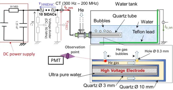
2.3 DBD Generation in bubbles in water using the DC power supply
The experimental setup for the DBD generation in bubble in water using the DC power supply is shown in Figure 10. The commercial AC power supply has been replaced by the designed DC power supply. Similarly, the DBD plasma has been generated corresponding to every switching time of SIDACs and detected by short surge of discharge current and light emitted from plasma (Figure 11). During every transition state of SIDACs, the pulse has been generated and the high voltage imposed on the discharge gap has led to a discharge, the discharge then has been terminated by its own characteristic as a dielectric discharge that reduces the current flow through SIDAC. When this current drops below the value of the holding current. These SIDACs are forced turning off and one working cycle completed. Consequently, the train of pulses and discharges have been alternatively generated with high stability.
9
Figure 10 Experimental setup of DBD generation in water using the DC power supply
a) b)
Figure 11 Experimental results of DBD generation in water using the DC power supply, overall waveform (a), and typical enlargement waveform (b)
10
3 Conclusions and future work
In this study, DBD plasma generation using SIDAC has been investigated as a sequence of a bubble formation and an electronic process within the bubbles. Experimentally, this DBD plasma has been generated efficiently in both cases in gas phase and in water. In both cases, SIDAC ON switching ignites DBD and self-termination DBD turns SIDAC OFF. These two characteristics switched alternatively make the whole system work continuously. The chemical process initiated by the discharge in water solution has been studied and estimated by the generation of reactive species and the decomposition of dye (MB) dissolved in water. The most important species with high oxidation potential as hydroxyl radical (OH) Oxygen atom (O), hydrogen peroxide (H2O2), Ozone, along with UV light have been detected by optical emission spectroscopy. The discharge has worked effectively on decomposing MB (model pollutant) in the tap water that is significantly enhance by introducing a small amount of Oxygen to main working gas. In order to extend the application of the plasma in a standalone renewable power system or in area without power grid connection, the novel DC power supply has been developed for DBD generation. The power supply has been designed with simple modular structure, has flexibly of connecting to a commercial DC power supply or independent solar power system, and applied successfully to effective DBD generation.
Since DBD in water initiate various physical and chemical processes and is strongly effected by various parameter especially high permittivity and conductivity of water. The detailed mechanism of the discharge is still not fully understood comparing to the discharge in gas phase.
Next important part of future works should be focused on temporal revolution of the DBD plasma in bubbles in water as well as its chemical processes.