INVITED PAPER
Special Section on Electronic DisplaysA New Eco-Friendly Photo Resist Stripping Technology Using
“Ethylene Carbonate”
Hiromitsu OTA†a), Hirofumi OTSUBO†, Motonori YANAGI†, Hisashi FUJII††,
and Yoshihito KAMIMOTO††, Nonmembers
SUMMARY Recently, it is demanded to form a high performance pat-tern on an enlarged circuit board in a low cost in the process to produce LCD devices. In the part of upgrading the performance, the materials are reexamined such as Al or Mo to Cu. Furthermore, in the process of reex-amining the materials, it is demanded that such materials are low in envi-ronmental load. Therefore, we examined if it is possible to reuse Ethylene Carbonate, a photo resist stripper, with low environmental load by decom-posing dissolved photo resist using ozone gas. Furthermore, we examined if it is possible to apply Ethylene Carbonate without damaging the next generation wiring materials. As a result, we were able to identify the most efficient condition for ozone gas to recycle Ethylene Carbonate used as a photo resist stripper. Ethylene Carbonate was not only suitable for Al· Mo wiring, but was also suitable for the next generation Cu wiring. There-fore by using Ethylene Carbonate for the new and old process for stripping photo resists, it is able to reduce the environmental load and also reduce the cost for stripping.
key words: eco-friendly new resist stripper 1. Outline of Technology
1.1 Past Technology
Recently, Amine system (will be abbreviated as “Amine”) strippers, such as “monoethanolamine” (will be abbreviated as “MEA”), “N-methylpyrrolidone” (will be abbreviated as “NMP”), were used as strippers to strip photo resist in the progress of manufacturing array for FPD’s [1]. Amine is very dangerous and highly toxic. Furthermore, used Amine will be disposed as waste. There is a report that disposing Amine will pollute the environment. To prevent this, it is said that Amine needs to be distilled to remove impurities before disposing [2]. Even when distilled, the impurities from the used Amine must be disposed and will be a great environmental load. Therefore, from the point of view of global warming, which is an international issue, the reex-amined material for the enlarged LCD device should be one that is not only safe but also low in environmental load. 1.2 EC Technology
This time we focused on an aprotic polar solvent, Ethylene
Manuscript received February 26, 2010. Manuscript revised June 11, 2010.
†The authors are with Nomura Micro Science Co., Ltd.,
Atsugi-shi, 243-0021 Japan.
††The authors are with Kanagawa Industrial Technology Center,
Ebina-shi, 243-0435 Japan.
a) E-mail: [email protected] DOI: 10.1587/transele.E93.C.1607
Carbonate (will be abbreviated as “EC”), an ethylene glycol with a cyclic carbonate ester which has a high polarity and has a high dissolution ability against water, organic solvents, and high-molecular substance [3]. (See Fig. 1) EC is being introduced to the array producing process of FPD for it is compatible structurally with positive photo resist and for it has a characteristic that the photo resist stripping rate is very high.
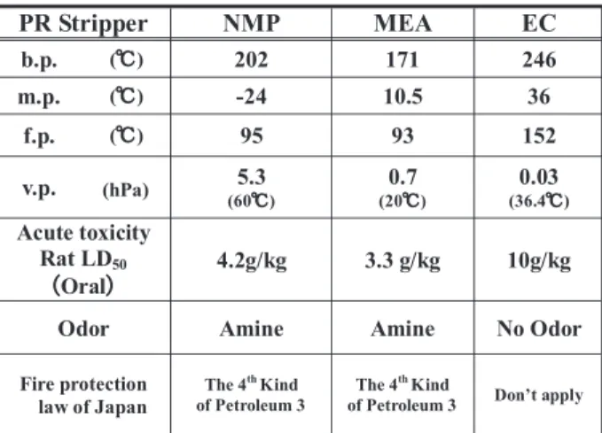
The basic physical properties of EC and Amine were compared. EC has a high boiling point, melting point and flash point, the vapor pressure is low and is non toxic. (See Table 1)
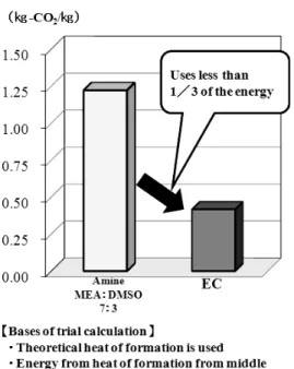
Furthermore, to see the environmental load, the out-put of CO2to produce 1 kg was calculated from the heat of
formation. Comparing EC and Amine (MEA: dimethyl sul-foxide (will be abbreviated as “DMSO”)= 7:3), the CO2
output of EC is 1/3 of that of Amine. (See Fig. 2) From this, it can be said that EC is safer and environmentally friendly compare to Amine.
Fig. 1 Structure of molecule.
Table 1 Comparison between photo resist strippers for LCD.
Fig. 2 Comparison of CO2emission between strippers.
Table 2 Photo resist stripping rate by EC temperature.
According to Muraoka, because EC is an aprotic polar solvent, dissolubility of ozone gas (will be abbreviated as O3) is low. It is reported that EC does not easily decompose
by O3[4].
Furthermore, according to Sato, the stripping rate of 1.5µm photo resist with ion inputted at 11B+ 1×10¹⁴/cm2
was 20 seconds at 80◦C and 10 seconds at 100◦C [5]. (See Table 2) It is reported that there is not much of a differ-ence between the stripping rates of O3 added photo resist
dissolved EC and a brand new EC [5]. (See Table 3) The film thickness of photo resist used for photolithography in LCD process is about 1.0∼2.5 µm. It is demanded to strip this in about 1 minute. It is possible to clear this demand by the stripping rate of EC. Furthermore, there are reports about As and P ion inputted photo resist other than B concerning photo resist stripping by EC [6], [7].
EC and Amine strips PR differently. Amine strips photo resist by chemically reacting with photo resist, de-composing the polymer chain. In this case, Amine mole-cules will come in contact with photo resist and will react
Table 3 Photo resist stripping rate of EC adding O3.
from the surface. Therefore, Amine molecules will reduce by repeating the chemical reaction, and will be in need to change the solution because the photo resist stripping power will reduce.
Different to Amine, EC strips photo resist by resolution reaction. By using EC repetitiously, the photo resist concen-tration in the solution will increase and exchange of solution will be in need likewise to Amine. However, as mentioned previously, EC is durable to O3. By adding O3, it is able to
decompose photo resist and the stripping power will reform making it possible to reuse EC.
Therefore, by utilizing the characteristic that EC is durable to O3, the main 2 points were examined for a
prac-tical use of the reusing technology [8].
1. To confirm that EC is a stripper that does not decom-pose by O3when recycled [8].
2. To confirm the most efficient photo resist decomposing condition by O3 and the by-products in that condition
[8].
Furthermore, the adaptability of EC for the next generation Cu wiring was examined.
3. To confirm that EC is applicable without damaging the new Cu metal wiring.
2. Experiments and Results
2.1 Confirmation of Decomposing Condition of Photo Re-sist and Durability of O3for EC
2.1.1 Experiments
To recycle EC, the amount of O3 needed to decompose
photo resist will be an important factor. Therefore, the fol-lowing experiment was performed to understand the decom-posing of photo resist in EC by O3. O3 (concentration:
10 g/Nm3) was added in the flow rate of 0.3 L/min to 50 g EC
containing 0.2 wt% photo resist. The photo resist decom-position was confirmed using HPLC, examining the height of peak of Novolak Resin which is the main component of photo resist. Further experiment was conducted by EC alone to confirm the durability of EC to O3.
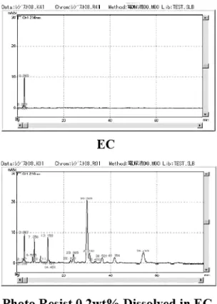
Fig. 3 HPLC analysis of EC before adding O3.
2.1.2 Results
Figure 3 shows the result of chromatogram before adding O3by HPLC. With the HPLC analysis condition, there was
no peak other than the peak at the retention time at 3 min for EC. Numerous peaks were detected for EC that contained 0.2 wt% photo resist. In these, the peaks at retention time around 30 min and 54 min were high and were specified as Novolak Resin. The decomposition condition was evaluated at these points.
From the HPLC measurement condition and Novolak Resin analysis result, it was interpreted that retention time over 20 min is the fundamental material of Novolak Resin and retention time under 20 min is photo conductor, remain-ing solvent, or photo resist decomposed by O3.
Figure 4 shows the chromatogram after decomposing EC containing 0.2 wt% photo resist by O3. “After
decom-posing” means the result of adding O3 for 30 min. It was
determined that chromatogram for EC alone did not differ from before adding O3. From this, it was verified that EC
has high durability to O3. Moreover, it was verified that EC
does not decompose easily by O3when recycled.
Next, it shows that the peak increased where retention time is less than 20 min, and it decreased where retention time is more than 20 min when EC contains photo resist 0.2 wt%. Moreover, the peak disappeared at retention time 54 min, and it decreased at retention time 30 min. From these two peaks, the quantity experiments of photo resist decomposition condition were determined.
Fig. 4 HPLC analysis of EC after adding O3.
Fig. 5 Time O3added and peak height of novlak resin using HPLC.
Based on this, HPLC analysis was conducted using the same experimental process as before, adding O3 at 5 min,
10 min, 15 min, and 30 min to EC containing photo resist 0.2 wt%.
Figure 5 shows the peak height of retention time 30 min and 54 min for each HPLC analysis result. From this, it was determine that adding time of O3and the height of the peak
are proportional. Moreover, by stating the peak height of 0 min after adding O3 as 1, it was able to find that when
height of the peak is at 0, it is the time that the photo resist has fully decomposed. From this, it was able to find the most suitable condition of O3to decompose photo resist. It
is able to decompose the photo resist in EC by adding the most sufficient amount of O3for the amount of photo resist
Fig. 6 Analysis of by-product by photo resist decomposition using 1H-NMR.
2.2 Conformation of Decomposition of Photo Resist and By-Products
2.2.1 Experiments
From the experiments mentioned previously in Sect. 2.1.2, it is possible to hypothesize the amount of O3 needed for
the decomposition. However, it is not possible to specify the by-products from the decomposition. It is possible that these by-products may have a bad influence on LCD metals wiring during photo resist stripping. To determine the by-products, experiment was conducted with the same operation as stated above and analyzed using 1H-NMR method. This time, the experiment was performed with photo resist concentration 5 wt%, and O3concentration 70 g/Nm3.
2.2.2 Results
Figure 6 shows the analysis of the hydrogen atom from the Novolak Resin, which is the main photo resist and by-products by 1H-NMR. The broadcloth peaks of Novolak Resin without adding O3 were confirmed at 2 ppm
(Ph-CH3), 4 ppm (Ph-CH2-Ph’), 7 ppm (Ph-H). However, those
peaks disappeared when O3 was added at 150 min. The
peaks were confirmed for Formic acid (-H) at 8 ppm, and Acetic acid (-CH3) at 1.9 ppm, although these were not
con-firmed at 0 min.
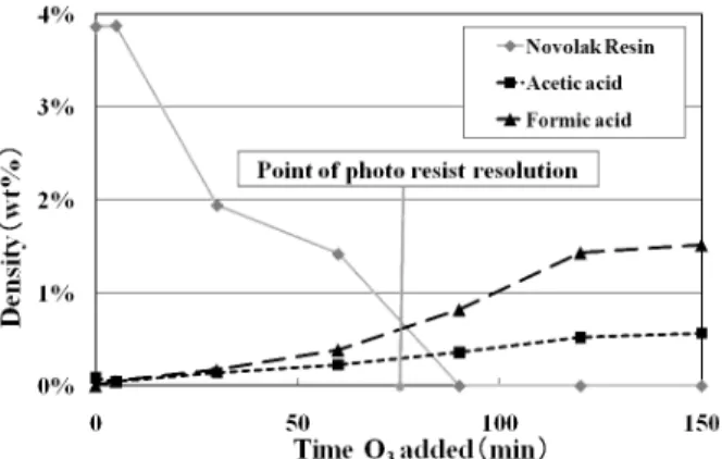
Figure 7 shows the analysis from the 1H-NMR data to see if the peaks of the Novolak Resin, Formic acid, and Acetic acid differ as the time after adding O3. It shows the
Novolak Resin, the main component of the photo resist, dis-appears and the by-products, formic acid and acetic acid, increased.
From this, we confirmed the decomposing point of the photo resist based on the analysis result by HPLC from Sect. 2.1.2. More than 80% of the photo resist was extinct and the concentration became about 0.5 wt%. Furthermore, it was recognized that the increase of the by-products were less than 1 wt%. Therefore, it was confirmed that by adding O3in the most suitable condition corresponding to the photo
resist, it is able to restrain the by-products.
Fig. 7 Relationship between O3adding time and by-product using 1H-NMR.
Fig. 8 Etching rate of metals by strippers.
2.3 Experiments of Etching Using LCD Metal Wiring 2.3.1 Experiments
Glass base test sample sputtered with Al, Mo and Cu met-als were dipped in 200 g EC at 80◦C which is stirred for 100 min. The same test was performed with Amine (MEA:DMSO= 7:3) as well and the result was compared. However, the temperature of Amine was set at 60◦C and be-cause the etching rate was fast, the dipping time for Cu was changed to 80 min. The damage for each metal by the strip-per was confirmed by calculating the etching rate using the metal quantity which eluted into the stripper which value was analyzed by ICP-MS.
2.3.2 Results
Figure 8 shows the etching rate by the strippers for 1 min of each metal. The etching rate for EC and Amine for Al was less than 0.02 Å/min, and for Mo it was less than 0.5 Å/min. Moreover, the Al and Mo etching rate of EC is slower than Amine. Especially, there were no elution for Al and was 0 Å/min. (Atomic diameter Al; 2.5 Å, Mo; 2.9 Å) Furthermore, the etching rate of Amine for Cu was very fast and was 20 Å/min, on the other hand, EC was less than
0.02 Å/min. (Atomic diameter Cu; 2.7 Å)
From these results, it can be said that EC does not dam-age as much as Amine for Al and Mo wiring and further-more, there is no damage to the Cu wiring. Therefore, it is understood that not only it is suitable for the present strip-per but is also suitable for the next generation stripstrip-per. As mentioned in Sect. 2.2.2, the by-products from photo resist decomposing are mainly carboxylic acid such as formic acid and acetic acid. There is a need to examine the effect on those metals wiring, however, it is able to control the by-products by recycling EC under the most suitable condition. Therefore, even when the recycling process using O3for EC
is adopted, it is possible to present a process without any damage to the metal wiring in the LCD producing line.
3. Conclusions
The following was understood about EC. 1. EC is durable to O3compare to photo resist.
2. It is possible to decompose photo resist efficiently un-der the most suitable condition and is able to control the amount of by-products.
3. EC is efficient to not only the Al and Mo LCD metal wiring, but is also efficient to the next generation wiring using Cu.
The output of CO2 in the process of producing EC is
very low. Moreover, it can be recycled and reused by us-ing O3 and is eco and low cost compared to Amine. Also,
it is able to control the amount of by-products in the pro-cess of decomposing photo resist in EC by using the effi-cient amount of O3 for the amount of photo resist in each
process. It can be said that using the recycling technology of EC using O3, it is able to suggest a damage free process
for not only for the present LCD metal wiring but also for the next generation LCD metal wiring. EC is a photo resist stripper which is safe and eco compared to Amine and it is low in cost for it can be recycled and be reused.
It is planned to develop this technology such as to im-prove the photo resist stripping efficiency.
References
[1] Y. Igarashi, “Current condition and movement of development for TFT-LCD manufacturing chemical,” GEKKAN Display 2006 Octo-ber, pp.40–45, Techno Times Company, Oct. 2006.
[2] M. Adachi, “Method to collect flux and flux collecting system,” Japan Patent Office, Patent applicant 2003-236328, Feb. 2002. [3] T. Iinuma and M. Hirakawa, “High purity ethylene carbonate: New
resist stripper,” Toagosei Annual Report of Research “TREND” 2004 #7, pp.42–45, Toagosei Co., Ltd., Jan. 2004.
[4] H. Muraoka, “Method to remove organic film and removal system,” Japan Patent Office, Patent 3914842, Aug. 2002.
[5] A. Sato, “Environmental and speedy photoresist removal with or-ganic solvent and ozone,” 49th Spring Meeting, 2002, The Japan Society of Applied Physics and Related Societies, Society of Ap-plied Physics, no.2, p.793, March 2002.
[6] F. Kobayashi, “Ion-implanted photo resist removal using solution,” Society of Applied Physics Hokuriku Shinshu Branch (2007), Soci-ety of Applied Physics Hokuriku Shinshu Branch Academic Lecture
Executive Committee, p.48, Nov. 2007.
[7] M. Igarashi, “Ion-implanted photoresist removal using chemicals,” Society of Applied Physics Hokuriku Shinshu Branch (2008), Soci-ety of Applied Physics Hokuriku Shinshu Branch Academic Lecture Program Editing Committee, p.20, Nov. 2008.
[8] H. Ota, “Recycling technology for resiststripper “Ethylene Carbon-ate” to decrease the environmental load,” 16th International Display Workshops Volume.1; International Display Workshops, pp.317– 320, Dec. 2009.
Hiromitsu Ota received B.E. degree in Kanagawa Institute of Technology in science and engineering in 1998. In 1998 he joined No-mura Micro Science and has been engaged in the research of photo resist stripper. He is a member of the Japan Society of Applied Physics.
Hirofumi Otsubo received B.E. degree in Saga University in engineering in 2002. In 2007 he joined Nomura Micro Science and has been engaged in the research of photo resist stripper.
Motonori Yanagi graduated Ube National College of Technology in 1983. He joined Mitsubishi Electric Corporation and has been engaged in the research of LSI. In 1995 he joined Nomura Micro Science and works as a general manager of the Technical Development Division today.
Hisashi Fujii received the M.E. degree from Yokohama National University, Japan, in 1993. He joined Kanagawa Industrial Technol-ogy Center in 1993, and has been engaged in the research of nanoparticle technology. He is a member of the Japan Society of Applied Physics and the Physical Society of Japan.
Yoshihito Kamimoto recived the B.E. de-gree in applied physics from Tokyo University, Tokyo, Japan, in 1989. In 1989, he joined the Steal Laboratory of NKK R and D Center, Kawasaki, Japan, and then joined Kanagawa In-dustrial Technology Center in 1998. He has been engaged in the research of nanoparticle technology. He is a member of the Japan So-ciety of Applied Physics.