JAXA Research and Development Report
February 2021
Japan Aerospace Exploration Agency
Cleanliness level of
the Extraterrestrial Sample Curation Center of JAXA
YOSHITAKE Miwa, NAKATO Aiko, KUMAGAI Kazuya, NISHIMURA Masahiro YADA Toru, TACHIBANA Shogo, OKADA Tatsuaki, ABE Masanao
YURIMOTO Hisayoshi, USUI Tomohiro and
Astromaterials Science Research Group
2. CLEANING METHOD FOR ITOKAWA SAMPLE HANDLING TOOLS 1
3. CLEANING METHOD FOR RYUGU SAMPLE HANDLING TOOLS 2
3.1. Analytical methods ··· 2
3.2. Sampling method and analysis results ··· 3
4. ENVIRONMENTAL MONITORTING 5
4.1. Sample collection methods ··· 5
4.2. Analytical methods ··· 6
4.3. Analysis results ··· 6
4.3.1. Wafer exposure method ··· 6
4.3.2. Atmosphere analysis ··· 15
5. SUMMARY 24
ACKNOWLEDGEMNETS 25
REFERENCES 25
Appendix 26
and Astromaterials Science Research Group
ABSTRACT
The Extraterrestrial Sample Curation Center of JAXA (ESCuC) accepts samples returned by asteroidal explorer. Such returned samples are handled by various techniques to prevent contamination from earth materials. So, we have adopted cleaning methods suitable for the material and application of tools, which will be introduced into the nitrogen-circulation-type clean chamber that handles the returned sample. The results of monitoring of cleanliness level of clean rooms and clean chamber after completions suggest that curation facility has been kept clean. Moreover, it was demonstrated that the atmosphere in the clean chamber was not affected by the clean room based on the metallic elements and organic materials.
Keywords: Itokawa, Ryugu, Curation, Cleanliness level of Clean Room, Sample return
1. INTRODUCTION
The Extraterrestrial Sample Curation Center of JAXA (ESCuC) accepts samples returned by both domestic and international asteroidal explorer, including Itokawa samples obtained by Hayabusa.
Compared to the extraterrestrial samples collected on the ground, samples obtained directly from asteroids are valuable because their origins are identifiable. Such returned samples are handled by various techniques to prevent contamination from earth materials.
We have adopted cleaning methods suitable for the material and application of tools, which will be introduced into the nitrogen-circulation-type clean chamber (CC) that handles the returned sample.
As Itokawa samples contain several fine particles (average particle size of approximately 45 µm), it is important to the contamination control even several micron particles. Hence, tools made of materials like stainless steel and aluminum alloys introduced into the CC have been subjected to “Full-Course”
cleaning (details are described separately), which is a useful method for the removal of fine particles.
The synthetic quartz tools and containers, which are resistant to the acids that directly contacted Itokawa samples, are cleaned by combining the
“Full-Course” cleaning with alkali cleaning/acid
cleaning, which is an effective method for removing metal elements
1). On the other hand, for the gold discs used in the initial description of Itokawa sample
2), acid cleaning causes the surface to become rough, causing its visibility to decrease; therefore, both “Full-Course” and alkali cleanings have been performed. We also have continued to monitor the environment of the ESCuC. Cleanliness has been continuously managed not only in the CC, but also in the clean room where the chamber was installed.
Moreover, it has been also managed in the booth where the tool is dried after cleaning. The details of the clean room and CC have been reported in the previous studies
2,3,4).
In this article, we report the details of the cleaning method for sample handling tools and monitoring results obtained in the sample-handling environment of the ESCuC. In December 2020, Hayabusa 2 plans to bring back Ryugu samples.
Therefore, we discribe a new cleaning scheme for tools for the handling of Ryugu samples.
2. CLEANING METHOD FOR ITOKAWA SAMPLE HANDLING TOOLS
All the tools (made of stainless steel and aluminum alloy) that are introduced into the clean chamber 2 (CC2), which are used to handle
*
Received November 25, 2020
*1
Department of Space Astronomy and Astrophysics, Institute of Space and Astronautical Science (ISAS)
*2
Marine Works Japan Ltd.
*3
Department of Earth and Planetary Science, The University of Tokyo
*4
Department of Natural History Sciences, Hokkaido University
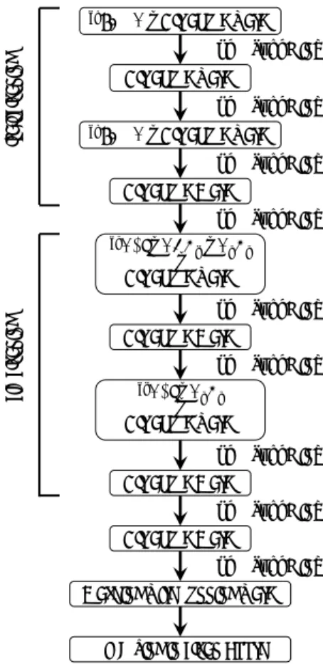
the samples, are subjected to the “Full-Course”
cleaning (Fig. 1). The “Full-course” cleaning have been an ultrasonic cleaning using 2-propanol (SC standard) and a 1:1 mixture of dichloromethane and methanol (both for dioxin analysis). The ultrasonic cleaning tubs were made of stainless steel and had a volume of 20–30 L. In addition, tools made of synthetic quartz glass which is resistant to acids and alkalis, are cleaned using an acid solution combined with a high-purity alkali cleaning solution (tetramethylammonium hydroxide: TMAH) for precise cleaning, hydrochloric acid, nitric acid, and hydrogen peroxide solution (both for ultrahigh-purity analysis) (Fig. 2).
3. CLEANING METHOD FOR RYUGU SAMPLE HANDLING TOOLS
It is expected that Ryugu sample, which is likely to retain information on asteroid formation, would contain a large amount of extraterrestrial organic matter compared to Itokawa sample. For Ryugu sample tool, the cleaning process was examined with the aim of efficiently removing fine particle contamination as in the cleaning process of Itokawa sample tool, and also removing organic contamination on the earth as much as possible.
3.1. Analytical methods
At the Renesas Semiconductor Manufacturing Naka plant, the synthetic quartz glass plates for the evaluation tests were prepared by contaminating it as uniformly as possible. It was analyzed the residual amounts of organic and metallic substances after cleaning in ESCuC. In addition, the contaminated synthetic quartz plate analysis results were used as reference.
For the evaluation of the organic substances, the organic impurities attached to the synthetic quartz plate were removed at 400 °C using a temperature-raising degassing device. It was then recaptured and measured by an adsorption tube (adsorbent: Tenax-GR) and gas chromatographic mass spectrometer equipped with purge and trap (Agilent 5973, GC-MS with P&T), respectively.
For the evaluation of the metal material, 3 mL of the sample and extract (0.35% HCl + 0.3%
H
2O
2) was enclosed in a 100-mL PFA bottle. The quartz plate was then eluted for five minutes.
The eluate was measured using a double- focusing inductively coupled plasma-mass spectrometer (ICP-MS), ELEMENT2 (Thermo Fisher Scientific).
2‐Propanol
Dichloromethane + Methanol 2‐Propanol
Ultrapure Water
Ultrapure Water
Ultrapure Water 38KHz 5min.
38KHz 5min.
38KHz 5min.
35KHz 5min. X 3 Flow rate: >120ml/sec.
98KHz 5min. X 3 Flow rate: >120ml/sec.
Air drying in clean booth 959KHz 5min. X 3 Flow rate: >120ml/sec.
Fig. 1. A schematic viewgraph of the procedure of the “Full-course” cleaning for tool that handles Itokawa sample.
*1TMAH + Ultrapure water
Ultrapure water
Ultrapure Water
*2HCl + HNO3+ H2O2 Ultrapure water+ Ultrapure Water
70℃, >10min.
70℃, >10min.
70℃, >10min.
70℃, >10min.
70℃, >10min.
Washing with running water 70℃, >10min.
*3HCl + H2O2 Ultrapure water+
Ultrapure Water Ultrapure Water
70℃, >10min.
70℃, >10min.
70℃, >10min.
*1TMAH + Ultrapure water
Air drying in clean booth
*1) TMAH(tetramethylammonium hydroxide) : Ultrapure water = 1:10, *2) HCl : HNO3: H2O2: Ultrapure water = 1:1:1:8, *3) HCl : H2O2: Ultrapure water = 1:1:9
Alkali cleaningAcid cleaning
Fig. 2. A schematic viewgraph of the procedure
of the “alkali/acid cleaning” for tool that handles
Itokawa sample.
For the evaluation of the synthetic quartz plates, the first wash evaluation was conducted from January to June 2019. The running water rinsing process, which was expected to remove the fine
cleaning and “alkali/acid cleaning,” (Fig. 3). In addition, to remove the contaminated organic matter, we tried two types of organic matter removal methods, the baking method and the UV irradiation method using ozone and confirmed which components each cleaning method was highly useful. In the evaluation conducted in 2019, six systems were subjected to cleaning processes.
To secure three samples per system, we divided them into three sets to perform the cleaning and analysis. Based on the results of 2019, we conducted a second cleaning evaluation by combining the
“alkali cleaning/acid cleaning” and UV irradiation to prevent the contamination of organic matter after cleaning in February 2020. This study in 2020 covered the cleaning processes of three systems, and because three samples were washed simultaneously, there was less variation within three samples compared to that of the results in 2019.
Before using, Pre-baking was performed three times at 450 °C for 6h and then cooled for one night.
The UV irradiation was performed using the UV cleaner by Filgen Inc. This was also performed three times pre-irradiation before using via UV irradiation for 30 min and atmospheric induction for 15 min.
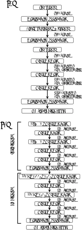
The results of the first and second cleaning evaluations of the metal elements (Fig. 4) revealed that the contaminants of the metal elements cannot be completely removed by the “Full-Course”
cleaning, “Full-Course cleaning + UV irradiation”, and “Full-Course cleaning + baking” cleaning methods alone were used. In addition, for Cr, it was shown that the baking operation increased the amount of contamination. For Al, the amount of contamination noticeably increased due to UV irradiation and the baking performed after the
“Full-Course” cleaning. This was hypothesized to be due to the quartz plate was left standing on the aluminum foil during the baking and UV irradiation.
Therefore, in the second wash evaluation, a quartz plate was fabricated to prevent the contamination of Al, and the sample was left to stand on the slatted quartz and subjected to UV irradiation.
Moreover, we found that the combination of alkali cleaning and acid cleaning with “Full-Course”
cleaning can remove the contaminations of different metallic elements. There was almost no difference in the effects of alkali and acid. Meanwhile, similar to that of the previous study
1), the combination of alkali and acid cleanings showed a slight improvement in the contamination of metal elements.
2‐Propanol
Dichloromethane + Methanol
2‐Propanol
Ultrapure Water
Ultrapure Water
Ultrapure Water 38KHz 5min.
38KHz 5min.
38KHz 5min.
35KHz 5min. X 3 Flow rate: >120ml/sec.
98KHz 5min. X 3 Flow rate: >120ml/sec.
Air drying in clean booth 959KHz 5min. X 3 Flow rate: >120ml/sec.
Washing with running water
Washing with running water
Washing with running water
*1TMAH + Ultrapure water Ultrapure water
Ultrapure Water
*2HCl + HNO3+ H2O2 + Ultrapure water Ultrapure Water
70℃, >10min.
70℃, >10min.
70℃, >10min.
70℃, >10min.
70℃, >10min.
Washing with running water 70℃, >10min.
*3HCl + H2O2 + Ultrapure water Ultrapure Water Ultrapure Water
70℃, >10min.
70℃, >10min.
70℃, >10min.
*1TMAH + Ultrapure water
Air drying in clean booth Ultrapure Water
70℃, >10min.
Washing with running water
Alkali cleaningAcid cleaning
Figure 3. A schematic viewgraph of the procedure of running water cleaning. (a) The “full‐course with running water” cleaning.
(b) The “acid‐alkali with running water” cleaning.
*1) TMAH(tetramethylammonium hydroxide) : Ultrapure water = 1:10, *2) HCl : HNO3: H2O2: Ultrapure water = 1:1:1:8, *3) HCl : H2O2: Ultrapure water = 1:1:9
(a) (b)
Fig. 3. A schematic viewgraph of the procedure of running water cleaning. (a) The “Full-course with running water” cleaning. (b) The “alkali/acid with running water” cleaning.
2‐Propanol
Dichloromethane + Methanol
2‐Propanol
Ultrapure Water
Ultrapure Water
Ultrapure Water 38KHz 5min.
38KHz 5min.
38KHz 5min.
35KHz 5min. X 3 Flow rate: >120ml/sec.
98KHz 5min. X 3 Flow rate: >120ml/sec.
Air drying in clean booth 959KHz 5min. X 3 Flow rate: >120ml/sec.
Washing with running water
Washing with running water
Washing with running water
*1TMAH + Ultrapure water Ultrapure water
Ultrapure Water
*2HCl + HNO3+ H2O2 + Ultrapure water Ultrapure Water
70℃, >10min.
70℃, >10min.
70℃, >10min.
70℃, >10min.
70℃, >10min.
Washing with running water 70℃, >10min.
*3HCl + H2O2 + Ultrapure water Ultrapure Water Ultrapure Water
70℃, >10min.
70℃, >10min.
70℃, >10min.
*1TMAH + Ultrapure water
Air drying in clean booth Ultrapure Water
70℃, >10min.
Washing with running water
Alkali cleaningAcid cleaning
Figure 3. A schematic viewgraph of the procedure of running water cleaning. (a) The “full‐course with running water” cleaning.
(b) The “acid‐alkali with running water” cleaning.
*1) TMAH(tetramethylammonium hydroxide) : Ultrapure water = 1:10, *2) HCl : HNO3: H2O2: Ultrapure water = 1:1:1:8, *3) HCl : H2O2: Ultrapure water = 1:1:9
(a) (b)
Occasionally, significantly d Figure 4. Elemental abundances on quartz glass plate determined by ICP-MS.
Fig. 4. Elemental abundances on quartz glass plate determined by ICP-MS.
as the third sample of the first wash evaluation in which Na, K, Ca, etc. were found, were probably operational contaminations.
For the organic matter, in addition to the “Full- Course cleaning”, by combining UV irradiation and baking, contamination was significantly removed (Fig. 5). On the other hand, it was also found that the alkali and acid cleanings were not effective for removing the contaminants of organic matter.
The running water rinsing process was compared to the “Full-Course + alkali cleaning”
process (Figs. 4 and 5), and no significant improvement in cleanliness was obtained.
This suggested that presently, cleanliness is more dependent on worker skill, procedures, and environment as opposed to improvement by adding the running water rinsing process. Therefore, we decided not to use the running water rinse step in the second wash evaluation.
Based on these results, after the alkali and acid cleanings (Fig. 4), no significant increase in the contamination of metal elements was observed after conducting UV radiation. Besides, we confirmed that it was effective in reducing contaminated organic matter that could not be decontaminated by the alkali cleaning/acid cleaning alone (Fig. 5).
Based on these results, the method for Ryugu sample, which was more important for organic matter than that of Itokawa sample, was to remove organic matter by UV irradiation after the “Full-
of materials that were resistant to acids and alkalis with the possibility of direct contact with Ryugu samples, we planned to subject them to UV irradiation after the “Full-Course” and alkali cleanings (Fig. 6b). We examined the effect of adding acid cleaning on the particle removal and operations efficiency, and judged that alkali cleaning alone can be expected to be sufficient for Ryugu samples because larger samples are likely to be handled. In addition, we decided not to perform a rinsing process by running water for this study.
4. ENVIRONMENTAL MONITORTING 4.1. Sample collection methods
In order to estimate the amount of contamination caused by metal elements and organic substances on the surface of the cleaned synthetic quartz glass in the chamber and clean room, the contaminants were obtained by the wafer exposure method.
The conditions of the wafer exposure method was leaving an 8-inch silicon wafer for about 15–20 h.
Moreover, to estimate the gaseous contaminants in the clean room, an impinger was used to obtain ambient air at a flow rate of 1.0 L/min for 17–19 h to evaluate the inorganic and metal ions. The organic matter was obtained at a rate of 0.5 L/
min for 1.5 h using an adsorption tube (adsorbent:
Tenax-GR).
The collection sites were Planetary Sample Handling Room 1 for Itokawa sample, Planetary Sample Handling Room 2 for Ryugu sample (completed in 2017), Manufacturing and Cleaning Room. Planetary Sample Handling Rooms 1 and 2 were Class 1000 clean rooms, while Manufacturing and Cleaning Room were class 10000 clean room. In addition, the following locations were also evaluated, clean chamber 2 Occasionally, significantly d Figure 4. Elemental abundances on quartz glass plate determined by ICP-MS.
Fig. 5. Organic compound abundance on quartz glass plates determined by TD-GC-MS.
Total amount of organic matter
Total amount of phthalate Ester Total amount of siloxane 1stset for the first time 2ndset for the first time 3rdset for the first time The second time
Fig. 5 Organic compound abundance on quartz glass plates determined by TD‐GC‐MS.
reference full course full course + UV full course + baking full course + alkali full course + acid full course + alkali‐acid full course + alkali + UV full course + alkali‐acid + UV reference full course full course + UV full course + baking full course + alkali full course + acid full course + alkali‐acid full course + alkali + UV full course + alkali‐acid + UV 101
102
1
10‐1
ng/cm2
10‐1 101
10‐3 1
10‐2 109 atoms/cm2
10‐1 1
10‐2
10‐3
ng/cm2
Fig. 6. A schematic viewgraph of the procedure of cleaning for tool that handles Ryugu sample. (a) for metal tools, (b) for glass and Teflon tools.
Figure 6. A schematic viewgraph of the procedure of cleaning for tool that handles Ryugu sample. (a) for metal tools, (b) for glass and Teflon tools.
Full‐course cleaning UV irradiation
Full‐course cleaning
UV irradiation Alkali cleaning Air drying in clean booth
(a) (b)
(CC2), 3-3 (CC3-3), 4-1 (CC4-1), 4-2 (CC4-2) and cleaning booths which made by resin and SUS for dry handling tools.
To assess the contamination during the transportation from the sampling to the analysis sites, the same tool used to collect the samples was transported simultaneously and set as the travel blank.
4.2. Analytical methods
The analysis was conducted at the Renesas Semiconductor Manufacturing Naka plant. The analysis of the metal elements that were collected using the wafer exposure method was conducted by applying the vapor-phase decomposition- ICP-MS (Agilent 7500s) after pretreatment using droplet scanning. In the analysis of the organic matter collected by the wafer exposure method, the organic impurities adhering to the wafer were desorbed by the temperature degassing device, and then recollected by the adsorption tube (absorbent: Tenax-GR). Moreover, the wafer heating degassing gas chromatograph mass spectrometry (GC-MS; Agilent 5973) with P & T was applied to the adsorption tube.
In addition, because the analysis pretreatment device of the organic matter used for the wafer exposure method was replaced in 2018, the results of the analysis of organic matter from 2018 onwards were shown. The results of the analysis of metal elements were compiled from 2013 to 2020.
The analysis of the inorganic ions obtained using the impinger was measured using ion chromatography of DX-500 and DX-120 for anions and cations, respectively. In addition, the metal elements obtained using the impinger were measured using a double-focusing ICP- mass spectrometer (Thermo Fisher Scientific, ELEMENT2 ICP-MS). The organic matter obtained using the solid-phase adsorption method was analyzed using the GC-MS with P&T (Agilent 5973).
4.3. Analysis results
4.3.1. Wafer exposure method
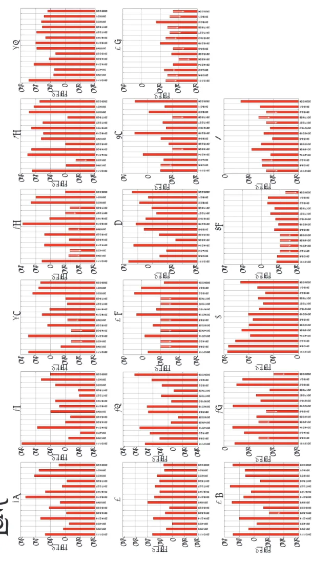
In the wafer exposure method, the amount of contamination can be monitored for particulate metals and organic substances. Figs. 7–11 show the results of the analysis of the metal elements and organic substances using the wafer exposure method. The respective measurement results of the blanks are shown in Figs. 7a and 8. The downward arrow in the figure indicates that the analysis value was less than or equal to the detection limit value.
(1) Planetary Sample Handling Room 1
The measurement results of the metallic elements in the Planetary Sample Handling Room 1 are shown in Fig. 7b. There was a variation in the metallic elements contained in the equipment such as Fe, Cu, Cr, Zn, Al, and Co, probably Mg from dust, and biological elements such as Na, K, and Ca. The metallic elements such as Fe, Ni, Cr, Al, and Mn in CC 2 (Fig. 9a), which form the chamber and tools, were likely to be higher. However, compared to that of the blanks, the other elements were stable and had low concentrations. Based on this, it can be observed that the CC2 was kept clean despite the variation in the concentration of the metal elements in Planetary Sample Handling Room 1.
The organic matters in Planetary Sample Handling Room 1 were detected to be one order of magnitude greater than those of the blanks (Fig. 8). On the other hand, the organic matters in the CC2 (Fig. 10a) were detected to be at an equal level as that of the blanks, showing that the amount of organic matter contamination in the measurement component was significantly low.
Hence, it was demonstrated that the atmosphere in the clean chamber was not affected by the clean room based on the metallic elements and organic materials.
(2) Planetary Sample Handling Room 2
The measurement results of Planetary Sample Handling Room 2 are shown in Fig. 7c. As for the metal elements, it was observed that the concentration was low when there was no equipment after the clean room was completed (September 2018), but Fe etc. have been detected after the introduction of the equipment. The 2019-2020 analysis results of the metallic elements in CC3-3, CC4-1, and CC4-2 (Fig. 9b), revealed that the metallic elements, such as Fe, Ni, Cr, Al, and Mn, which formed the chamber and tools, tended to be detected at high levels, which was the same trend as that in CC2.
On the other hand, the levels of Cu, Zn, K, Ca, and Mo were slightly higher than those in CC2.
This suggested that the environment inside the chamber was not stable because CC3-3, CC4-1, and CC4-2 were new, and rehearsal operations for the return samples was ongoing.
The organic matter in Planetary Sample
H a n d l i n g R o o m 2 a l s o s h o w e d h i g h
concentrations of contamination compared to
that in Planetary Sample Handling Room 1
(Fig. 8). This was probably due to the release
of contaminants from the building materials,
assembly of the tools, devices etc.
Fig ur e 7 . E le m en ta l a bu nd an ce s o n S i W af er d et er m in ed b y V PD -ICP -MS .T he do w nw ar d ar ro w in the fi gur e indi ca te s t ha t t he an al ysi s v al ue w as l ess t ha n o r e qu al to th e d et ec tio n l im it v al ue .( a) tr av el bl ank (r ef er enc e) , ( b) Pl ane ta ry Sa m pl e ha ndl ing ro om 1, (c ) Pl ane ta ry Sa m pl e ha ndl ing ro om 2 , ( d) M anuf ac tur ing a nd cle ani ng ro om .
(a ) Fe Cu Ni Cr Zr Na K Ca M n Al Ti M o M g Co B Sn W
104 103 102 101 1 10-1 10-2
ng/
3 m
103 102 101 1 10-1 10-2
ng/
3 m
103 102 101 1 10-1 10-2
ng/
3 m
103 102 101 1 10-1 10-2
ng/
3 m
103 102 101 1 10-1 10-2
ng/
3 m
104 103 102 101 1 10-1 10-2
ng/
3 m
102 101 1 10-1 10-2 10-3
ng/
3 m
102 101 1 10-1 10-2 10-3
ng/
3 m
102 101 1 10-1 10-2 10-3
ng/
3 m
101 1 10-1 10-2 10-3
ng/
3 m
1 10-1 10-2 10-3
ng/
3 m
103 102 101 1
ng/
3 m
1 10-1 10-2 10-3
ng/
3 m
102 101 1 10-1 10-2
ng/
3 m
101 1 10-1 10-2 10-3
ng/
3 m
10 1 10-1 10-2
ng/
3 m
10 1 10-1 10-2
ng/
3 m
Fig. 7. Elemental abundances on Si W afer determined by VPD-ICP-MS. The downward arrow in the figure indicates that the analysis value was less than or equal to the detection limit value. (a) Travel blank (reference), (b) Planetary Sample Handling Room 1, (c) Planetary Sample Handling Room 2, (d) Manufacturing and Clea ning Room.
(b ) Fe Cu Ni Cr Zr Na K Ca M n Al Ti M o M g Co B Sn W
104 103 102 101 1 10-1 10-2
ng/
3 m
103 102 101 1 10-1 10-2
ng/
3 m
103 102 101 1 10-1 10-2
ng/
3 m
103 102 101 1 10-1 10-2
ng/
3 m
103 102 101 1 10-1 10-2
ng/
3 m
104 103 102 101 1 10-1 10-2
ng/
3 m
102 101 1 10-1 10-2 10-3
ng/
3 m
102 101 1 10-1 10-2 10-3
ng/
3 m
102 101 1 10-1 10-2 10-3
ng/
3 m
101 1 10-1 10-2 10-3
ng/
3 m
1 10-1 10-2 10-3
ng/
3 m
103 102 101 1
ng/
3 m
1 10-1 10-2 10-3
ng/
3 m
102 101 1 10-1 10-2
ng/
3 m
101 1 10-1 10-2 10-3
ng/
3 m
10 1 10-1 10-2
ng/
3 m
10 1 10-1 10-2
ng/
3 m
Fig ur e 7 . E le m en ta l a bu nd an ce s o n S i W af er d et er m in ed b y V PD -ICP -MS .T he do w nw ar d ar ro w in the fi gur e indi ca te s t ha t t he an al ysi s v al ue w as l ess t ha n o r e qu al to th e d et ec tio n l im it v al ue .( a) tr av el bl ank (r ef er enc e) , ( b) Pl ane ta ry Sa m pl e ha ndl ing ro om 1, (c ) Pl ane ta ry Sa m pl e ha ndl ing ro om 2 , ( d) M anuf ac tur ing a nd cle ani ng ro om .
(c) Fe Cu Ni Cr Zr Na K Ca M n Al Ti M o M g Co B Sn W
104 103 102 101 1 10-1 10-2
ng/
3 m
103 102 101 1 10-1 10-2
ng/
3 m
103 102 101 1 10-1 10-2
ng/
3 m
103 102 101 1 10-1 10-2
ng/
3 m
103 102 101 1 10-1 10-2
ng/
3 m
104 103 102 101 1 10-1 10-2
ng/
3 m
102 101 1 10-1 10-2 10-3
ng/
3 m
102 101 1 10-1 10-2 10-3
ng/
3 m
102 101 1 10-1 10-2 10-3
ng/
3 m
101 1 10-1 10-2 10-3
ng/
3 m
1 10-1 10-2 10-3
ng/
3 m
103 102 101 1
ng/
3 m
1 10-1 10-2 10-3
ng/
3 m
102 101 1 10-1 10-2
ng/
3 m
101 1 10-1 10-2 10-3
ng/
3 m
10 1 10-1 10-2
ng/
3 m
10 1 10-1 10-2
ng/
3 m
(d ) Fe Cu Ni Cr Zr Na K Ca M n Al Ti M o M g Co B Sn W
104 103 102 101 1 10-1 10-2
ng/
3 m
103 102 101 1 10-1 10-2
ng/
3 m
103 102 101 1 10-1 10-2
ng/
3 m
103 102 101 1 10-1 10-2
ng/
3 m
103 102 101 1 10-1 10-2
ng/
3 m
104 103 102 101 1 10-1 10-2
ng/
3 m
102 101 1 10-1 10-2 10-3
ng/
3 m
102 101 1 10-1 10-2 10-3
ng/
3 m
102 101 1 10-1 10-2 10-3
ng/
3 m
101 1 10-1 10-2 10-3
ng/
3 m
1 10-1 10-2 10-3
ng/
3 m
103 102 101 1
ng/
3 m
1 10-1 10-2 10-3
ng/
3 m
102 101 1 10-1 10-2
ng/
3 m
101 1 10-1 10-2 10-3
ng/
3 m
10 1 10-1 10-2
ng/
3 m
10 1 10-1 10-2
ng/
3 m
Fig ur e 8. O rg ani c c om po und abunda nc e on Si W af er de te rm ine d by T D- GC -M S. T he d ow nw ar d ar ro w in th e fig ur e in di ca te s t ha t t he a na lysi s v al ue w as l ess t ha n o r e qu al to th e d et ec tio n l im it v al ue .
201 8/1 1/1 6
201 9/2 /1
201 9/3 /8
201 9/1 2/1 1
202 0/2 /26
202 0/7 /31
201 9/1 0/4
201 8/1 1/1 6
201 9/2 /1
202 0/2 /26
201 8/1 1/1 6
201 9/1 2/1 1
202 0/2 /26
202 0/7 /31
201 9/1 0/4
201 8/1 1/1 6
201 9/2 /1
202 0/7 /31
201 9/1 0/4
Tot al am oun t o
f r tte c ma ani org
ng/
2 cm
5 4 3 2 1 0
travel blank PSHR1 PSHR2 MCR
Tot al am oun t o
f er Est ate hal pht
ng/
2 cm
10
11 10
-210
-310
-410
-Tot al am oun t o
f e xan silo
ng/
2 cm
0. 15 0.1 0. 05 0
Travel
Fig. 8. Or ganic compound abundance on Si W afer determined by TD-GC-MS. The downward arrow in the figure indicates that the analysis value was less than or equal to the detection lim it value. PSHR1: Planetary Sample Handling Room 1, PSHR2: Planetary Sample Handling Room 2, MCR: Manufacturing and Cleaning Room.
Fi gu re 9 . E le m en ta l a bu nd an ce s o n S i W af er d et er m in ed b y V PD -IC P- M S. Th e do w nw ar d ar ro w in th e fig ur e in dic at es th at th e an aly sis v alu e w as le ss th an o r e qu al to th e de te ct io n lim it va lu e. (a ) C le an c ha m be r 2 in P la ne ta ry s am pl e h an dl in g r oo m 1 , ( b) C le an c ha m be r 3 a nd 4 in P la ne ta ry s am pl e ha ndl ing ro om 2 , ( c) C le an Bo ot h in M anuf ac tur ing and cl ea ni ng ro om .
(a ) Fe Cu Ni Cr Zr Na K Ca M n Al Ti M o M g Co B Sn W
101 1 10-1 10-2
ng/
3 m
103 102 101 1 10-1 10-2
ng/
3 m
102 101 1 10-1
ng/
3 m
102 101 1 10-1 10-2
ng/
3 m
104 103 101 1 10-1 10-2
102
ng/
3 m
103 102 101 1 10-1
ng/
3 m
103 102 101 1 10-1 10-2
ng/
3 m
103 102 101 1 10-1 10-2
ng/
3 m
101 1 10-1 10-2 10-3
ng/
3 m
102 101 1 10-1 10-2
ng/
3 m
10 1 10-1 10-2
ng/
3 m
103 102 101
ng/
3 m
1 10-1 10-2 10-3
ng/
3 m
102 101 1 10-1 10-2
ng/
3 m
101 1 10-1 10-2
ng/
3 m
102 1 10-1 10-2
101
ng/
3 m
101 1 10-1 10-2
ng/
3 m
Fig. 9. Elemental abundances on Si W afer determined by VPD-ICP-MS. The downward arrow in the figure indicates that the analysis value was less than or equal to the detection limit value. (a) Clean chamber 2 in Planetary Sample Handling Room 1, (b) Clean chamber 3 and 4 in Planetary Sample Handling Room 2, (c) Clean booth in Manufacturing and Cleaning Room.
(b ) CC 3-3 CC 4-1 CC 4-2 Fe
Cu Ni Cr Zr Na K Ca M n Al Ti M o M g Co B Sn W
101 1 10-1 10-2
ng/
3 m
103 102 101 1 10-1 10-2
ng/
3 m
102 101 1 10-1
ng/
3 m
102 101 1 10-1 10-2
ng/
3 m
104 103 101 1 10-1 10-2
102
ng/
3 m
103 102 101 1 10-1
ng/
3 m
103 102 101 1 10-1 10-2
ng/
3 m
103 102 101 1 10-1 10-2
ng/
3 m
101 1 10-1 10-2 10-3
ng/
3 m
102 101 1 10-1 10-2
ng/
3 m
10 1 10-1 10-2
ng/
3 m
103 102 101
ng/
3 m
1 10-1 10-2 10-3
ng/
3 m
102 101 1 10-1 10-2
ng/
3 m
101 1 10-1 10-2
ng/
3 m
102 1 10-1 10-2
101
ng/
3 m
101 1 10-1 10-2
ng/
3 m
(c) Re sin cle an b oo th SU S cl ea n bo ot h Fe Cu Ni Cr Zr Na K Ca M n Al Ti M o M g Co B Sn W
101 1 10-1 10-2
ng/
3 m
103 102 101 1 10-1 10-2
ng/
3 m
102 101 1 10-1
ng/
3 m
102 101 1 10-1 10-2
ng/
3 m
104 103 101 1 10-1 10-2
102
ng/
3 m
103 102 101 1 10-1
ng/
3 m
103 102 101 1 10-1 10-2
ng/
3 m
103 102 101 1 10-1 10-2
ng/
3 m
101 1 10-1 10-2 10-3
ng/
3 m
102 101 1 10-1 10-2
ng/
3 m
10 1 10-1 10-2
ng/
3 m
103 102 101
ng/
3 m
1 10-1 10-2 10-3
ng/
3 m
102 101 1 10-1 10-2
ng/
3 m
101 1 10-1 10-2
ng/
3 m
102 1 10-1 10-2
101
ng/
3 m
101 1 10-1 10-2
ng/
3 m
analyses of the organic matter in the chambers. In the Ryugu chamber, the total amount of organic matter and concentration of phthalate esters, which
were plasticizers, tended to be higher than that in the Itokawa chamber. This is thought to suggest that the materials used during manufacturing have not withered because the chamber is new (completed in 2018). In addition, it can be seen that the cleanliness is not stable and the variations large due to the putting in and taking out of newly manufactured tools.
(3) Manufacturing and Cleaning Room
The measurement results of the Manufacturing and Cleaning Room for the tool cleaning are shown in Fig. 7d. For the metal elements, it was observed that the amounts of contaminants were approximately the same as that of the clean room of class 1000 where Planetary Sample
Handling Rooms 1 and 2 are. The results of the metal elements of booths for the drying of the cleaning tools installed in the Manufacturing and Cleaning Room are shown in Fig. 9c. As a result, the cleanliness of booths used for drying the tools was well maintained compared to that of clean chambers, which handled the sample.
Although siloxanes and increasing of organic matter was occasionally detected in the Manufacturing and Cleaning Room, the cleanliness of this room was as high as that of the class 1000 clean room (Fig. 8). On the other hand, the clean booth showed lower cleanliness than that of clean chambers in terms of organic matter (Fig. 11).
Therefore, the SUS clean booth was introduced separately from the conventional resin clean booth to reduce the organic matter contamination.
However, it did not lead to a significant reduction in the amount of contamination. We will continue to monitor the amount of contamination of the metal elements and organic substances in the resin and SUS products to be able to determine and use the better product.
4.3.2. Atmosphere analysis (1) Inorganic ions
The results of the ion chromatographic analysis of the inorganic ions obtained from the impinger are shown in Fig. 12. The highly volatile acetate and formic acid ions, which were derived from building materials, and ammonium ions, which were derived from the air, workers, and various types of materials, were significantly detected.
In addition, the nitrate ions derived from the air Fig. 10. Organic compound abundance on Si Wafer
determined by TD-GC-MS. (a) Total amount of organic matter, (b) Total amount of phthalate Ester.
Fig. 11. Organic compound abundance on Si Wafer of clean booth in Manufacturing a n d C l e a n i n g R o o m determined by TD-GC-MS.
(a) Total amount of organic
matter, (b) Total amount of
phthalate Ester, (c) Total
amount of siloxane.
Fig ur e 12 . I no rg ani c c om po und abunda nc e in the a ir de te rm ine d by im pi ng er co lle ct io n .T he do w nw ar d ar ro w in the fi gur e indi ca te s th at th e an al ys is va lu e w as le ss th an o r e qu al to th e de te ct io n lim it va lu e. (a ) T ra ve l b la nk (r ef er enc e) , ( b) Pl ane ta ry Sa m pl e Ha ndl ing Ro om 1 , ( c) Pl ane ta ry Sa m pl e Ha ndl ing R oo m 2 , ( d) M anuf ac tur ing a nd cle ani ng R oo m .
(a ) Cl
-NO
2-NO
3-F
-Lact ic Aci d NH
4-Ace tic Aci d Fo rm ic Aci d
SO
42-40 30 20 10 0
ng/
3
m
10
210
11 10
-110
-2ng/
3
m
10
210
11 10
-1ng/
3
m
410
210 1
-110
ng/
3
m
10
310
110
410
21 10
-1ng/
3
m
10
310
110
410
21 10
-1ng/
3
m
10
310
110
310
110
-110
-2ng/
3
m
10
21
10
310
110
-110
-2ng/
3
m
10
21
10
410
110
-110
-2ng/
3
m
10
21
10
3Fig. 12. Inor ganic compound abundance in the air determined by impinger collection . The downward arrow in the figure indica tes that the analysis value was less than or equal to the detection limit value. (a) Travel blank, (b) Planetary Sample Handling Room 1, (c) Planetary Sample Handling Room 2, (d) Manufacturing and Cleaning Room.
(b ) Cl
-NO
2-NO
3-F
-Lact ic Aci d NH
4-Ace tic Aci d Fo rm ic Aci d SO
42-40 30 20 10 0
ng/
3
m
10
210
11 10
-110
-2ng/
3
m
10
210
11 10
-1ng/
3
m
410
210 1
-110
ng/
3
m
10
310
110
410
21 10
-1ng/
3
m
10
310
110
410
21 10
-1ng/
3
m
10
310
110
310
110
-110
-2ng/
3
m
10
21
10
310
110
-110
-2ng/
3
m
10
21
10
410
110
-110
-2ng/
3
m
10
21
10
3(c) Cl
-NO
2-NO
3-F
-Lact ic Aci d NH
4-Ace tic Aci d Fo rm ic Aci d SO
42-40 30 20 10 0
ng/
3
m
10
210
11 10
-110
-2ng/
3
m
10
210
11 10
-1ng/
3
m
410
210 1
-110
ng/
3
m
10
310
110
410
21 10
-1ng/
3
m
10
310
110
410
21 10
-1ng/
3
m
10
310
110
310
110
-110
-2ng/
3
m
10
21
10
310
110
-110
-2ng/
3
m
10
21
10
410
110
-110
-2ng/
3
m
10
21
10
3(d ) Cl
-NO
2-NO
3-SO
42-F
-Lact ic Aci d NH
4-Ace tic Aci d Fo rm ic Aci d
40 30 20 10 0
ng/
3
m
10
210
11 10
-110
-2ng/
3
m
10
210
11 10
-1ng/
3
m
410
210 1
-110
ng/
3
m
10
310
110
410
21 10
-1ng/
3
m
10
310
110
410
21 10
-1ng/
3
m
10
310
110
310
110
-110
-2ng/
3
m
10
21
10
310
110
-110
-2ng/
3
m
10
21
10
410
110
-110
-2ng/
3