九州大学学術情報リポジトリ
Kyushu University Institutional Repository
The Anteroposterior Axis of the Proximal Tibia Can Change After Tibial Resection in Total Knee Arthroplasty: Computer Simulation Using Asian Osteoarthritis Knees
牛尾, 哲郎
http://hdl.handle.net/2324/2236126
出版情報:九州大学, 2018, 博士(医学), 課程博士 バージョン:
権利関係:
Basic Science
The Anteroposterior Axis of the Proximal Tibia Can Change After Tibial Resection in Total Knee Arthroplasty: Computer Simulation Using Asian Osteoarthritis Knees
Tetsuro Ushio, MD, Hideki Mizu-uchi, MD, PhD
*, Ken Okazaki, MD, PhD, Yuan Ma, MD, Umito Kuwashima, MD, Yukihide Iwamoto, MD, PhD
Department of Orthopaedic Surgery, Graduate School of Medical Sciences, Kyushu University, Higashi-ku, Fukuoka, Japan
a r t i c l e i n f o
Article history:
Received 21 June 2016 Received in revised form 26 August 2016
Accepted 8 September 2016 Available online 28 September 2016
Keywords:
total knee arthroplasty computer simulation tibial rotational alignment anteroposterior axis osteoarthritis
a b s t r a c t
Background:We evaluated the effect of cutting surface on the anteroposterior (AP) axis of the proximal tibia using a 3-dimensional (3D) bone model to ensure proper tibial rotational alignment in total knee arthroplasty.
Methods:3D bone models were reconstructed from the preoperative computed tomography data of 93 Japanese osteoarthritis knees with varus deformity. The AP axis was defined as the perpendicular bisector of the medial and lateral condylar centers in a 3D coordinate system. Bone cutting of the proximal tibia was performed with various tibial posterior slopes (0, 3, 7) to the mechanical axis, and we compared the AP axes before and after bone cutting.
Results:The AP axis before bone cutting crossed a point at about 16% (one-sixth) of the distance from the medial edge of the patellar tendon at its tibial attachment. The AP axis after bone cutting was signifi- cantly internally rotated at all posterior slopes: 4.1at slope 0, 3.0at slope 3, and 2.1at slope 7. The percentages of cases with differences of more than 3or 5were 66.7% and 34.4% at slope 0, 53.8% and 24.7% at slope 3, and 38.3% and 11.8% at slope 7, respectively.
Conclusion:The AP axis of the proximal tibia may be rotated internally after resection of the proximal tibia in total knee arthroplasty. Hence, surgeons should recognize the effect of changes in the cutting surface on rotational alignment of the proximal tibia.
©2016 Elsevier Inc. All rights reserved.
Total knee arthroplasty (TKA) has become one of the most successful orthopedic procedures for providing pain relief and improving knee function, with reported survival rates of greater than 90% after 15 years[1,2]. Proper positioning of TKA components is important for good clinical outcomes because component mal- positioning can lead to TKA failure due to aseptic loosening [3], instability[4], polyethylene wear[5], and patellar dislocation[6].
Malrotation of the tibial component has been found to affect patient-perceived outcomes; in particular, internal rotational errors can lead to patellofemoral problems[6], anterior knee pain[7], and
knee stiffness[8]. However, several previous studies reported that accurate tibial rotational alignment is challenging and concluded that the percentage of cases with acceptable postoperative align- ment ranged from 38% to 46%[9,10].
There is less consensus concerning which preoperative plans and surgical techniques will achieve proper tibial rotational align- ment. Some reasons for this disagreement concerns methods of evaluation and measurement. First, many anatomic landmarks for rotational reference exist but none has been universally accepted.
For example, Akagi's anteroposterior (AP) axis[11], one of the most famous references, is the line connecting the middle of the poste- rior cruciate ligament to the medial border of the patellar tendon attachment; however, this axis is based on normal knees, and posterior cruciate ligament attachment is sometimes unclear intraoperatively. Other recommended AP axes also show discrep- ancy between their theoretical underpinnings in published studies and practice in actual surgery[12,13]. Second, many evaluations have reduced accuracy due to the 2-dimensional (2D) analysis of One or more of the authors of this paper have disclosed potential or pertinent
conflicts of interest, which may include receipt of payment, either direct or indirect, institutional support, or association with an entity in the biomedicalfield which may be perceived to have potential conflict of interest with this work. For full disclosure statements refer tohttp://dx.doi.org/10.1016/j.arth.2016.09.003.
*Reprint requests: Hideki Mizu-uchi, MD, PhD, Department of Orthopaedic Surgery, Kyushu University, 3-1-1 Maidashi, Higashi-ku, Fukuoka 812-8582, Japan.
Contents lists available atScienceDirect
The Journal of Arthroplasty
j o u rn a l h o m e p a g e : w w w . a r t h r o p l a s t y j o u r n a l . o r g
http://dx.doi.org/10.1016/j.arth.2016.09.003 0883-5403/©2016 Elsevier Inc. All rights reserved.
computed tomography (CT) slices. CT slices are affected by the orientation of the patient's legs during the scan, and the width of CT slices affects the determination of anatomic landmarks[14,15]. In addition, Hirschman et al[14]concluded that rotational measure- ments on 2D CT showed wide variability and were significantly less reliable than 3-dimensional (3D) CT. Due to these problems, 3D evaluation appears to be the most optimal approach for acquiring proper tibial rotational alignment.
As for surgical techniques, there are several pitfalls concern- ing accurate implantation of the tibial component. Intra- operatively, insufficient posterolateral view, impingement of the popliteus tendon, and cementfixation can affect the position of the tibial component [7,9]. Of these factors, the shape of the cutting surface of the proximal tibia can have the most signifi- cant impact on the position of the component because surgeons tend to subjectively determine the position based on the appearance of the shape. In addition, it is difficult to use the same AP axis before and after cutting the tibial bone because of changes in the surface. Thus, it is important to understand the bone morphology of the tibia to align the component via accu- rate preoperative planning. Recently, several studies used com- puter simulations to assess the relationship between the bone morphology of the proximal tibia and rotational alignment [16,17]. However, most studies enrolled subjects with normal knees[16]rather than those with osteoarthritis (OA) and did not take tibial posterior slope into account[16,17]. Surgeons would likely benefit from evaluating the effect of the cutting surface using a 3D computer simulation, which reproduces intra- operative factors encountered in actual TKA surgery, such as degenerative changes and tibial posterior slope.
We previously performed a 3D computer simulation to evaluate problems with surgical techniques[18-20]and accuracy of preop- erative planning[15]. The purpose of the present study was to evaluate the effect of the cutting surface on the AP axis of the proximal tibia using a 3D bone model. Virtual surgeries were per- formed with various tibial posterior slopes on OA knees to measure the difference between before and after bone cutting. We hypoth- esized that the AP axis of the proximal tibia would change after resection in OA knees, especially under different tibial posterior slopes.
Patients and Methods Patients
Ninety-three Japanese OA knees with varus deformity were investigated in 89 patients before primary TKA. The study group consisted of 20 men and 69 women. Individuals with rheuma- toid arthritis, a history of knee injuries or infections, or severe bone defects in the proximal tibia were excluded. Preoperative demographic data are presented inTable 1. The preoperative femorotibial angle and progression of OA (determined using the Kellgren-Lawrence [K-L] OA scale[21]) were measured on full-
length, weight-bearing AP radiographs using the digital mea- surement software 2D template (Japan Medical Materials Corp., Osaka, Japan). In this study, most knees were classified as grade 4 on the K-L OA scale (83 knees), whereas the others were grade 3. This study was approved by the Institutional Review Board of Kyushu University (ID number of the approval: 25-74). Informed consent was obtained from all patients before their participation.
Three-Dimensional Bone Model and the Coordinate System
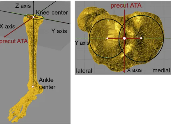
Preoperative CT scans of the unilateral lower extremity were obtained from all patients within 3 months before the scheduled surgery. CT slices were obtained with a 2-mm thickness. 3D bone models were reconstructed from preoperative CT data using MIMICS (Materialise, Leuven, Belgium). The bony geometry was imported into a computer-assisted design software program (Rhinoceros; Robert McNeel and Associates, Seattle, WA) in stereolithography format as our previous papers re- ported[19,20]. The coordinate system was adopted based on the study of Cobb et al [22]. Medial and lateral articular surface centers of the proximal tibia were determined by drawing the best-fit circle around the edge of the cortex of each plateau (Fig. 1). The knee center was defined as the origin of the co- ordinates for the midpoint of the line connecting the medial and lateral condylar centers (Figs. 1 and 2). The Z-axis of the tibia (proximal-distal) was defined as the tibial mechanical axis that connected the knee center and the ankle center. The ankle center was defined as the geometric center of talar dome (center of the trochlea of the talus)[10,23]. The plane normal to the Z-axis at the center of the knee was defined as the XY plane. The X-axis (anterior-posterior) was defined as the perpendicular bisector of the medial and lateral condylar centers projected onto the XY plane; this bisector was named the precut anatomic tibial axis (precut ATA; Fig. 2). The Y-axis (medial-lateral) was defined as the extension of the line connecting the medial and lateral condylar centers projected onto the XY plane.
Virtual Surgery: Cutting the Proximal Tibial Bone
Bone cutting was performed on the tibial bone model using the 3D coordinates. The tibial bone model had no cartilage from CT data; however, previous articles reported that a lateral cartilage Table 1
Preoperative Demographic Data.
Average±Standard Deviation (Range)
Age (y) 76.2±6.2 (55-89)
Femorotibial angle () 183.6±4.2 (176-196.7)
Height (cm) 151.6±9.7 (136-178)
Weight (kg) 62.4±12.1 (41.3-90.2)
Body mass index (kg/m2) 26.9±4.2 (18.9-36.9)
Knee extension () 6.9±5.7 (20 to 0)
Kneeflexion () 124.4±12.4 (80-150)
Fig. 1.Definition of knee center. MC, medial condylar center; LC, lateral condylar center; KC, knee center, defined as the midpoint between MC and LC.
T. Ushio et al. / The Journal of Arthroplasty 32 (2017) 1006e1012 1007
thickness is approximately 2 mm[24,25]. The resection level of the tibia was 8 mm below the deepest point of lateral articular surface to ensure 10 mm thickness of bone cutting accurately. We cut the proximal tibial bone along the precut ATA in the XY plane. Three
different tibial posterior slopes were simulated at 0, 3, and 7 relative to the tibial mechanical axis. After the bone resection, medial and lateral cutting surface centers of the proximal tibia were determined by drawing the best-fit circle around the edge of the Fig. 2.Definition of the 3-dimensional coordinate system. The origin of the coordinate system: knee center. Z axis (proximal-distal), mechanical axis defined as the line between the knee center and ankle center. X axis (anterior-posterior), the perpendicular bisector of the medial and lateral condylar centers projected onto the normal plane of the Z axis; precut ATA, precut anatomic tibial axis.
Fig. 3.Cutting the proximal tibial bone with 3 different posterior tibial slopes. The cutting direction of the tibia was along the precut ATA in the XY plane with 3 different posterior tibial slopes (0, 3, and 7relative to the tibial mechanical axis). After bone resection, the new AP axis (postcut ATA) was marked on the cutting surface. AP, anteroposterior.
cortex of each plateau using the same technique as described above.
Then, the new AP axis (postcut ATA) was defined as the perpen- dicular bisector of the medial and lateral condylar centers projected onto the XY plane (Fig. 3).
Evaluation of Precut and Postcut ATA
First, we measured the angle between the precut ATA and Akagi's AP axis [11] to evaluate the precut ATA (Fig. 4A). In addition, the point where the precut ATA crossed the patellar tendon at its attachment was investigated (Fig. 4B). The patellar tendon width (L) and the width medial to the crossing point (M) were measured, and the medial percentage width (M/L100) was calculated[11,26]. Second, we measured the rotational angle between precut and postcut ATA to evaluate the postcut ATA at each posterior slopes. The rotational angle was defined as posi- tive if the postcut ATA was externally rotated relative to the precut ATA. We also evaluated whether the femorotibial angle and K-L OA scale were associated with the rotational angle of the postcut ATA.
Statistical Analysis
To investigate the reliability and reproducibility of this coordinate system, intraobserver and interobserver reliabilities were assessed by intraclass correlation coefficients [ICC (1,1) and ICC (2,1), respec- tively][27]. All measurements were obtained by 2 orthopedic sur- geons (TU, YM) at an interval of more than 1 week. The data were blinded and included no patient information. A pairedt-test was used to compare the rotational angles between the precut and postcut ATA at each posterior slopes. Pearson's correlation coefficient was used to investigate the correlation between the rotational angle and femo- rotibial angle, and Spearman's correlation was used to evaluate the correlation between the rotational angle and K-L OA scale. Data analysis was performed using JMP Pro software version 11 (SAS Institute, Cary, NC). Statistical significance was set at aPvalue<.05.
Results
The ICC (1,1) and ICC (2,1) of this coordinate system were 0.95 and 0.94, respectively, suggesting excellent agreement for both.
Fig. 4.Evaluation of the precut ATA. (A) the angle between the precut ATA and Akagi's AP axis, (B) medial percentage width was defined as M/L100 at the patellar tendon attachment level (medial edge: 0%, lateral edge: 100%). M, width from the medial edge to the crossing point. L, width of the patellar tendon.
Fig. 5.Distribution of cases stratified by the rotational angle of postcut ATA compared with precut ATA for each of the 3 tibial posterior slopes.
T. Ushio et al. / The Journal of Arthroplasty 32 (2017) 1006e1012 1009
The average precut ATA was rotated externally compared with the Akagi's AP axis (4.9±5.1; range,11.6to 15.8). The medial percentage width (M/L100) was 16.3%±17.4% (range,40.0% to 59.0%) at the point where the precut ATA crossed. On average, the postcut ATA was significantly internally rotated relative to the precut ATA at all posterior slopes:4.1±3.2(13.7to 2.8) at slope 0,3.0±2.9(12.6to 4.6) at slope 3, and2.1±2.9 (11.7to 5.3) at slope 7(P<.001). There was a significant dif- ference among 3 tibial posterior slopes (P<.001).Figure 5shows the distribution of cases stratified by the rotational angle of postcut ATA compared with precut ATA for each of the 3 tibial posterior slopes (Fig. 5). The postcut ATA was internally rotated compared to that of the precut ATA in 94.6% (88 cases) at slope 0, 87.0% (81 cases) at slope 3, and 81.7% (76 cases) at slope 7. In addition, the percentages of cases with differences of more than 3or 5were 66.7% and 34.4% at slope 0, 53.8% and 24.7% at slope 3, and 38.3%
and 11.8% at slope 7, respectively.
Only a slight correlation was detected between the rotational angle of the postcut ATA and FTA (slope 0:r¼ 0.241,P¼.0272;
slope 3:r¼ 0.233,P¼.0344; slope 7:r¼ 0.221,P¼.0431). There was no significant correlation between the rotational angle of the postcut ATA and K-L OA scale for any of the 3 slopes (P¼.778-.93).
Discussion
The most importantfinding of the present study was that the AP axis of the proximal tibia may be significantly internally rotated after proximal tibial resection during TKA surgery. Internal
malrotation of the tibial component should be avoided to decrease the chance of patellofemoral problems, anterior knee pain, and knee stiffness[7,8]. In terms of clinical relevance, our results indi- cated that unexpected internal malrotation of the tibial component can occur relative to the planned and precut conditions if the sur- geon subjectively bases thefinal position of the tibial component on the shape of the tibial cutting surface. Forster-Horvath et al[16]
reported a similar trend in which internal rotation error was induced at a mean of 4.0 after proximal tibial resection. Their study evaluated normal knees with no tibial posterior slope and was not based on actual TKA surgery. Our study demonstrated the effect of the shape of the cutting surface on tibial component malpositioning by evaluating actual OA knees and taking tibial posterior slope into account.
In more than 80% of the cases in this study, the postcut ATA was internally rotated relative to the precut ATA at all tibial posterior slopes. Although the average rotational angle was small, the per- centages of cases with differences of more than 5 were 36% at slope 0, 22% at slope 3, and 12% at slope 7, respectively; these rates cannot be ignored considering that the definition of mala- lignment was reported as beyond 3-5from the target alignment [9,10,13,23,28]. Some previous studies concluded that the post- operative alignment of the tibial component tends to be internally rotated relative to the ideal position [9,10,29]. In addition, the accuracy of rotational tibial component angles within±3 of the ideal in conventional TKA was only 38%-46% [9,10]. Computer- assisted systems have been developed to improve the accuracy of conventional methods; however, most image-free navigation Fig. 6.Above (sagittal view): comparison of the morphology of the lateral and medial plateaus between 0and 7posterior slopes; dotted line shows the cutting line at 0of posterior slope and solid line showed the cutting line at 7of posterior slope. Below (axial view): white circles show the condylar centers at 0of posterior slope and black triangles show the condylar centers at 7of posterior slope.
systems cannot improve tibial rotational alignment relative to conventional TKA[23,30]. Even in a previous study using a CT- based navigation system, 21.4% of cases were outside the ideal range in terms of tibial rotational alignment[10]. Several pitfalls are known to exist regarding accurate implantation of the tibial component; however, our results suggest that surgeons should objectively evaluate the cutting surface and understand the precut and postcut morphological changes that occur in TKA.
References for aligning the AP axis of the proximal tibia have varied widely among studies, and there has been some controversy regarding which AP axis should be used to acquire the ideal rota- tional alignment[11,13,26,31]. One reason is the technical difficulty of using the same AP axis both before and after cutting due to the change in the shape of the articular surface. It would be ideal to identify the features of the cutting surface so surgeons could avoid changing the AP axis after cutting the bone. In this study, the precut ATA was rotated externally by an average of 5 compared with Akagi's AP axis, and it crossed a point at about 16% (one-sixth) of the distance from the medial edge of the patellar tendon at its tibial attachment. Regarding the AP axis after cutting the bone, Kawahara et al[26]recommended that in order to avoid rotational mismatch with the femoral side in OA knees, the modified AP axis should connect the geometric center of the cutting surface and the medial one-sixth of the border of the patellar tendon at the tibial attach- ment. Based on their results and our present results concerning the precut ATA, we consider that the medial one-sixth of the border of the patellar tendon at the tibial attachment may be a reliable landmark to permit the same AP axis to be used both before and after cutting of the proximal tibia.
The definition of the tibial AP axis should be as accurate as possible to avoid measuring errors. Measurement of AP axes with CT slices (2D measurement) were affected by the orientation of the patient's legs during the scan and the width of the CT slices[14,15].
Cobb's method, used in this study, was reported as the most reliable approach to determining the rotational alignment of the proximal tibia based on the centers of the unresected medial and lateral plateaus[22,32]. The ICC of the coordinate system reported by Cobb and that of our own system were 0.94-0.95, suggesting good agreement[22]. In addition, we previously performed a 3D com- puter simulation to evaluate problems with surgical techniques [18-20]and accuracy of preoperative planning[15]. Our 3D evalu- ation in this study should be more reliable than that of previous studies using 2D measurements and as such should be clinically helpful for surgeons.
Tibial posterior slope affected the postcut ATA; specifically, the difference compared to the precut ATA decreased with greater tibial slopes. In this simulation, we performed the bone cutting based on the knee center and the precut ATA. Posterior slopes caused the anterior margin of the medial plateau to move anteriorly, and the anterior margin of the lateral plateau to move posteriorly, due to the morphology of the proximal tibia (Fig. 6). The medial condylar center moved anteriorly and the lateral condylar center moved posteriorly with Cobb's method, resulting in a smaller amount of internal rotation (Fig. 6).
The present study has several limitations. First, no valgus OA knees were included in this study. The cutting level should be different in valgus knees if the cut is performed perpendicular to the mechanical axis, indicating that the shape of the cutting surface is different. Our results may have been different if valgus knees were included, but it was important to standardize the sample using individuals with similar deformities, and most knees in our hospital had varus deformities. Second, the knee center defined in this study might differ from those in actual clinical situations.
However, it would be difficult to use the same knee center in actual surgery. We believe that accurate evaluation was performed with
our coordinate system, which was validated as a reliable tool by several previous studies[22,32]. Third, no clinical knee conditions have been included in the present study. It is difficult to conclude whether the small change in the rotational angle is clinically sig- nificant, particularly with less constrained femoral-tibial articula- tions. In addition, we did not evaluate inaccuracy of cutting direction and bone thickness which can happen in actual TKA surgery. Fourth, this study did not evaluate the effect of the shape of the tibial baseplate. More research will be necessary once addi- tional computer-aided design models become available in the future. Despite these limitations, our 3D computer simulation provided valuable data in which the AP axis derived from the shape of the proximal tibia was rotated internally.
In conclusion, the AP axis of the proximal tibia can be signifi- cantly internally rotated after resection of the proximal tibia during surgery in TKA. The postcut ATA was internally rotated compared to the precut ATA in 94.6% (88 knees) of cases at slope 0, and the percentage of cases with a rotational angle of more than 5 was 66.7% at slope 0. Hence, to avoid malrotational alignment, sur- geons should recognize that the shape of the cutting surface has an effect on the AP axis.
References
1.Rodricks DJ, Patil S, Pulido P, et al. Press-fit condylar design total knee arthroplasty. Fourteen to seventeen-year follow-up. J Bone Joint Surg Am 2007;89:89.
2.Vessely MB, Whaley AL, Harmsen WS, et al. The Chitranjan Ranawat Award:
Long-term survivorship and failure modes of 1000 cemented condylar total knee arthroplasties. Clin Orthop Relat Res 2006;452:28.
3.Wasielewski RC, Galante JO, Leighty RM, et al. Wear patterns on retrieved polyethylene tibial inserts and their relationship to technical considerations during total knee arthroplasty. Clin Orthop Relat Res 1994:31.
4.Kim YH, Park JW, Kim JS, et al. The relationship between the survival of total knee arthroplasty and postoperative coronal, sagittal and rotational alignment of knee prosthesis. Int Orthop 2014;38:379.
5.Parratte S, Pagnano MW, Trousdale RT, et al. Effect of postoperative mechanical axis alignment on thefifteen-year survival of modern, cemented total knee replacements. J Bone Joint Surg Am 2010;92:2143.
6.Berger RA, Crossett LS, Jacobs JJ, et al. Malrotation causing patellofemoral complications after total knee arthroplasty. Clin Orthop Relat Res 1998:144.
7.Nicoll D, Rowley DI. Internal rotational error of the tibial component is a major cause of pain after total knee replacement. J Bone Joint Surg Br 2010;92:1238.
8.Bedard M, Vince KG, Redfern J, et al. Internal rotation of the tibial component is frequent in stiff total knee arthroplasty. Clin Orthop Relat Res 2011;469:2346.
9.Kuriyama S, Hyakuna K, Inoue S, et al. Tibial rotational alignment was signifi- cantly improved by use of a CT-navigated control device in total knee arthro- plasty. J Arthroplasty 2014;29:2352.
10.Mizu-uchi H, Matsuda S. The evaluation of post-operative alignment in total knee replacement using a CT-based navigation system. J Bone Joint Surg Br 2008;90:1025.
11. Akagi M, Oh M, Nonaka T, et al. An anteroposterior axis of the tibia for total knee arthroplasty. Clin Orthop Relat Res 2004:213.
12.Mizu-uchi H, Matsuda S, Miura H, et al. The effect of ankle rotation on cutting of the tibia in total knee arthroplasty. J Bone Joint Surg Am 2006;88:2632.
13.Uehara K, Kadoya Y, Kobayashi A, et al. Anthropometry of the proximal tibia to design a total knee prosthesis for the Japanese population. J Arthroplasty 2002;17:1028.
14.Hirschmann MT, Konala P, Amsler F, et al. The position and orientation of total knee replacement components: a comparison of conventional radio- graphs, transverse 2D-CT slices and 3D-CT reconstruction. J Bone Joint Surg Br 2011;93:62.
15.Okamoto S, Mizu-uchi H, Okazaki K, et al. Two-dimensional planning can result in internal rotation of the femoral component in total knee arthroplasty. Knee Surgery Sports Traumatol Arthrosc 2016;24:229.
16.Forster-Horvath C, Kremo V, Müller-Gerbl M, et al. Using the anatomical tibial axis for total knee arthroplasty alignment may lead to an internal rotation error.
Int Orthop 2015;39:2347.
17. Nakamura S, Morita Y, Ito H, et al. Morphology of the proximal tibia at different levels of bone resection in Japanese knees. J Arthroplasty 2015;30:2323.
18.Fukagawa S, Matsuda S, Mitsuyasu H, et al. Anterior border of the tibia as a landmark for extramedullary alignment guide in total knee arthroplasty for varus knees. J Orthop Res 2011;29:919.
19.Mizu-uchi H, Colwell CW, Matsuda S, et al. Effect of total knee arthroplasty implant position on flexion angle before implant-bone impingement.
J Arthroplasty 2011;26:721.
T. Ushio et al. / The Journal of Arthroplasty 32 (2017) 1006e1012 1011
20.Mizu-uchi H, Colwell CW, Fukagawa S, et al. The importance of bony impingement in restricting flexion after total knee arthroplasty. computer simulation model with clinical correlation. J Arthroplasty 2012;27:1710.
21. Kellgren J. Radiological assessment of osteo-arthrosis. Ann Rheum Dis 1957;16:494.
22.Cobb JP, Dixon H, Dandachli W, et al. The anatomical tibial axis: reliable rotational orientation in knee replacement. J Bone Joint Surg Br 2008;90-B:
1032.
23.Matziolis G. A prospective, randomized study of computer-assisted and con- ventional total knee arthroplasty; three-dimensional evaluation of implant alignment and rotation. J Bone Joint Surg Am 2007;89:236.
24.Matsuda S, Miura H, Nagamine R, et al. Anatomical analysis of the femoral condyle in normal and osteoarthritic knees. J Orthop Res 2004;22:104.
25.Tashiro Y, Uemura M, Matsuda S, et al. Articular cartilage of the posterior condyle can affect rotational alignment in total knee arthroplasty. Knee Surgery Sports Traumatol Arthrosc 2012;20:1463.
26.Kawahara S, Okazaki K, Matsuda S, et al. Medial sixth of the patellar tendon at the tibial attachment is useful for the anterior reference in rotational
alignment of the tibial component. Knee Surgery Sports Traumatol Arthrosc 2014;22:1070.
27.Walter SD, Eliasziw M, Donner A. Sample size and optimal designs for reliability studies. Stat Med 1998;17:101.
28.Kawahara S, Okazaki K, Matsuda S, et al. Internal rotation of femoral component affects functional activities after TKA-survey with the 2011 knee society score.
J Arthroplasty 2014;29:2319.
29.Barrack RL, Schrader T, Bertot AJ, et al. Component rotation and anterior knee pain after total knee arthroplasty. Clin Orthop Relat Res 2001:46.
30.Hasegawa M, Yoshida K, Wakabayashi H, et al. Minimally invasive total knee arthroplasty: comparison of jig-based technique versus computer navigation for clinical and alignment outcome. Knee Surgery Sports Traumatol Arthrosc 2011;19:904.
31. Insall JN, Easley ME. Surgical techniques and instrumentation in total knee arthroplasty. In: Insa JN, Scott WN, editors. Surg knee. 3rd ed. New York:
Churchill-Livingstone; 2001. p. 1553.
32.Victor J, Van Doninck D, Labey L, et al. How precise can bony landmarks be determined on a CT scan of the knee? Knee 2009;16:358.