大気圧マイクロ波放電ジェット・プラズマの流体力学的特性
Fluid Mechanical Characteristics of Microwave Discharge Jet Plasmas
at Atmospheric Gas Pressure
高村秀一†, 齋藤誠紀†, 櫛田玄一郎†, 神藤正士††, 大野哲靖††† Shuichi TAKAMURA, Seiki SAITO, Genichiro KUSHIDA, Masashi KANDO, Noriyasu OHNO Abstract Fluid mechanical properties of microwave discharge jet for argon and helium plasmas at
atmospheric gas pressure is investigated. Kelvin-Helmholtz(K-H) instability due to shear flow of working gas with surrounding air is seen to reflect on the plasma structure. Pulsation phenomenon for helium plasma jet is found not to have a counterpart in gas fluid behavior. Flickering phenomenon is shared in both jet diffusion flame and plasma jet. Ascending flow due to buoyancy effect and convection surrounding air to be followed by vortex formation originated from K-H instability would be the physical mechanism for the flickering.
1. Introduction
“Flow” in magnetized plasmas has attracted many interests in terms of its dynamic behavior, plasma confinement, structural formation and so on1). The gas flow has a general importance in fluid mechanics owing to a development of turbulence, gas mixing in diffusion
flame2), gas flow dynamics and many other
applications. The plasma jet discharge in atmospheric gas pressure may contain combined characteristics: flow of working gas and electrostatic force among plasma particles. The fluid mechanical property of gas flow may influence on the discharge phenomena3), and the electrostatic collective force of plasma may produce or modify the gas flow4). The plasma-induced gas flow is a typical example for such interactions. We may expect a new research area of electrostatic fluid dynamics of plasma/gas mixture by investigating
† Faculty of Engineering, AIT, Toyota 470-0392 †† Graduate School of Engineering,
NagoyaUniversity, Nagoya 464-8603
††† Research Institute of Electronic Engineering, Shizuoka University, Hamamatsu 432-8011
atmospheric jet discharge sustained with microwave power in terms of interactions between plasma and gas flows5).
In this research work, the following three topics have been investigated: 1) Kelvin-Helmholtz instability in quasi-steady state, 2) Pulsation phenomenon of helium jet column, and 3) Buoyancy effect including upward movement after ignition. The first and last topics concern gas fluid dynamic behavior, and the second one suggests some interaction between gas and plasma. Fluid dynamic approach for the jet discharge plasma has been found very few so far. We suppose that the present work would play a role of door to the electrostatic fluid mechanics for the medium of plasma/gas mixture.
2. Plasma Generation Device
Figure 1 shows the experimental device for generation of plasma jet at atmospheric gas pressure. The microwave circuit with a coupling launcher for plasma jet shown in Fig. 1(a) has an isolator and an E-H tuner ensuring a stable transfer of 2.45 GHz microwave power of less than 1.0 KW through WRJ-2 waveguide to the launcher, employing TE01 electromagnetic mode
structure.
The tapered waveguide makes the electric field of
TE01 mode at the narrow gap section strong, and
moreover the short plunger produces a standing wave so that the electric field may become maximum of standing wave at the launcher position on the straight waveguide with a small height between H-planes of waveguide. The distance between the short plunger and the launcher is set at an odd multiple number of a quarter λg, where λg is the wavelength in the waveguide and equal to 147.7 mm. Currently the odd number is 9 or 11.
We employed the TIAGO (Torche à Injection Axiale sur Guide d’Ondes, in French) nozzle for the launcher and gas injection developed by Moisan for the
microwave-sustained plasma torch6), as shown in
Fig.1(b).
A typical photo of torch plasma is shown in Fig.1(c), corresponding so called normal straight discharge mode with a spindle shape, one of the bifurcated discharge mode7).
3. Dynamics of Plasma Jet 3・1 Kelvin-Helmholtz instability
The normal argon plasma jet seems to have a spindle shape on a still photo as shown in Fig.1(c). However, a high-speed imaging with a frame rate around 10,000 (FASTCAM. Photron Co.) reveals various kinds of structural dynamics. Figure 2 shows some examples, where (a) shows a time evolution of upward propagation of turbulent structure, while (b) indicates the presence of threshold flow rate (~0.25 L/min) to have an instability. The propagation speed is summarized in Fig.3(a) for two kinds of nozzles and is evaluated to be between a gas flow velocity and a half of it at the nozzle exit. The growth of transverse fluctuation is plotted as a function of gas flow speed (rate) in Fig.3(b), showing clearly a threshold value of 0.25 L/min. These photos indicate that the shear flow across the jet with a surrounding atmospheric air brings Fig.1 Experimental Device. (a) Microwave circuit for
plasma jet discharge, (b)TIAGO nozzle set on the straight waveguide for microwave sustained plasma torch, and (c) a typical still photo of argon plasma jet with spindle shape.
Fig.2 Structural dynamics of Ar jet plasmas. (a) A series of plasma images taken with a high speed camera. The interval between images is 100 μs which means photos are displayed by every 4 images taken with the frame speed of 40,000 fps. (b) Dependence of gas flow rate on the dynamic structure.
Kelvin-Helmholtz instability, produces eddies around the shear layer8) and makes a 3-D spiral structure9). These are well-known as a turbulent structure in free jet.
The fluctuation frequencies observed at several heights from the nozzle head increase with the increase in Ar gas flow rate as shown in Fig.4(a). But the Strouhal number defined by
𝑆𝑡 =𝑓𝑑
𝑢 (1)
where d0 is the nozzle hole diameter, u0 is the gas flow
velocity, does not change much with the change in Ar gas flow rate as shown in Fig.4(b). These values are similar to the values expected in the fluid mechanic situation for K-H instability as shown in Fig.5(a) for the jet diffusion flames2). Fig.5(b) shows the temperature distribution, indicating that the threshold Reynolds number defined by
Re =ρu d
η (2)
where ρ is the mass density andη is the viscosity, is about 1000. In the case of argon plasma jet shown in Fig.3, Re ~800 for the threshold value estimated at room temperature.
Fig.3 Growth of unstable structure with increase in gas flow velocity for Ar plasma jet. Dependence of gas flow velocity on (a) the propagation speed and (b) horizontal fluctuation amplitude.
Fig.4 Fluid dynamic properties for plasma jet. (a) Fluctuation frequency and (b) Strouhal number as a function of Ar gas flow rate, taking the height as a parameter.
Fig.5 Fluid mechanical properties for jet diffusion flames2). (a) Distribution of Strouhal number as a function of streaming distance. (b) Temperature distributions for three different Reynolds numbers, 500, 1000 ad 2000 from top to bottom.
G. Kushida tried to investigate 3-D structure for coaxial jet intending the study on gas mixing processes9), which shows a kind of spiral structure as shown in Fig.6 where the top view represents contour of constant pressure, and the bottom does time averaged velocity vector distribution in the plane normal to jet axis.
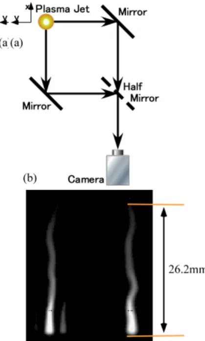
Motivated by the above work, we have tried to catch 3-D structure of plasma jet, by employing a simple optical system shown in Fig.7(a) which makes possible a simultaneous high speed imaging of jet plasma with orthogonal observation line of sight. Figure 7(b) is a typical example of photos in which very clear two images are successfully obtained although a spurious small shadow is contaminated due to a finite thickness of half mirror. Figure 8 shows a series of reconstructed 3-D strings of Ar jet plasmas. Very similar to the jet diffusion flame shown in Fig.6, a kind of spiral motion was successfully identified, indicating a clock-wise motion along the flow direction. Upward propagation of fluctuation is also clear as was shown in Fig.2.
In the case of helium plasma jet, the high-speed imaging reveals a movement of very bright core column attached on the nozzle head, which will be shown in Fig.12. The brightness is too large to catch weak emissions in the area above them. However, a careful observation brings us a turbulent structure visible as shown in Fig.9 where γ correction was carried out to enhance the structure above the bright column so that the critical He flow velocity for Kelvin-Helmholtz instability was determined as 30 m/s.
In a numerical simulation, Kushida confirmed that this kind of turbulent structure occurs also for normal neutral gas flow, as shown in Fig.10.
These critical flow velocities to have K-H instability for helium as well as argon plasma jets are summarized by using the gas Reynolds number where the viscosity is evaluated at room temperature as given by Fig.1110). Table 1 gives Reynolds numbers above which we have K-H instabilities not only for plasma jets but also for diffusion flame. These values are not so different within the factor of 2. Therefore, we conclude that the turbulence observed through the visible emission from the jet plasma comes from the K-H instability induced by the gas flow shear. It suggests that a suppression of gas flow turbulence could produce a longer jet column than the present plasma flame3). Fig.6 3-D structures of jet diffusion flame9). a)
Contour of constant pressure and (b) time averaged velocity distribution in the plasma normal to jet axis.
Fig.7 Optical system for obtaining 3-D structure of plasma jet string. (a) Optical system for high speed imaging and (b) a typical example of thus obtained images.
Critical Reynolds Number @300K
Ar (5 m/s) He (30 m/s) Diffusion Flame Plasma Jet 800 480 1000 Gas
Table 1 Critical Reynolds number for plasma jet and diffusion flame at the gas temperature of 300K.
Gas: Ar Flow Velocity: 17 m/s Power: 380W 0 0.2 0.4 0.6 0.8 time [ms] Top view 3D view (a) (b) (c) 1.0 1.0 1.0 1.0 1.0 1.0 1.0 1.0 1.0 1.0 1.0 10.0 1.0 1.0 10.0 1.0 1.0 10.0 1.0 1.0 10.0 1.0 1.0 10.0 1.0 Twin image
Fig.8 Reconstructed 3-D strings of Ar jet plasmas. (a) Twin image obtained with the optical system shown in Fig.7, (b) Top view, and (c) 3D representation. Scale is in mm.
Fig.9 Time evolution of turbulent fluctuations in helium plasma jet. In order to make clear the image contrast above the bright core column, γcorrection is carried out (γ= 0.6).
Fig.10 2D simulation for typical turbulent structure of free helium gas jet with the nozzle similar to the TIAGO. A mixing of helium with surrounding air due to Kelvin-Helmholtz instability is shown by color. 0.5 0.4 0.3 0.2 0.1 0 0 5 10 15 20 Ar-He Mixtures p =100 kPa x Ar + (1- x) He TEMPERATURE, T [103 K] Pure He Pure Ar x = 1.0 0.8 0.6 0.4 0.2 0.0
Fig.11 Temperature dependence of viscosity for Ar-He gas mixture10).
3・2 Pulsation in He plasma jet
Observation of bright vertical column of helium plasma jet shown in Fig.12 indicates a typical periodic motion with a period of 2.8 ms, as shown in Fig.12(a), to which we gave a name of “pulsation”. Such a structural dynamic behavior has never been detected in argon plasma jet. The bright column itself increases in length when the gas flow rate increases as shown in Fig.12(b).
Time traces of visible light emission from the head of bright vertical column have been registered with a photo diode and an amplifier as shown in Fig.13. The microwave power signals have been incorporated with the above optical information as represented in Fig.14. There is a strong correlation between the sharp increase in light intensity and spikes of incident and reflected microwave power signals coming from thyrister noise for power regulation. We note that the period 2.8 ms corresponds to 360 Hz = 60×6 Hz. It seems that a very small fluctuation of incident microwave power may bring such a pulsive behavior, but the reason why is open to solve at the moment. We also should note that some relaxation process with a decay time of a few milliseconds can be identified in time series data of reflected microwave power coming from the directional coupler. We suppose some coupling between gas flow and plasma properties through microwave discharge. 3-D observation with orthogonal line of sight reveals that the movement of helium bright column is not spiral but plane-like.
3・3 Buoyancy effect on plasma jet
Unsteady behavior of jet diffusion flame due to buoyancy driven flow has been investigated numerically11),12) and experimentally13). The flickering frequency has been found to be order of 10 Hz. The flickering mechanism is explained in terms of vortex growth induced by Kelvin-Helmholtz instability and their downward convection of surrounding air. Especially, a constriction of flame is considered to come from an excess of oxygen mixing rate due to the surrounding vortex13).
In the case of argon and helium plasma jet, very similar unsteady flickering has been observed under the condition of small gas flow rate as shown in Fig.15. However, the sustainment of plasma jet is not by combustion but by ionization of neutral particles with microwave power so that it is very interesting to know the physical mechanism for flickering in terms of microwave power absorption to the gas fluid. We understand that the ascending flow due to buoyancy effect and convection of surrounding air following vortex formation originated Kelvin-Helmholtz instability would be the physical mechanism.
Fig.12 Bright core column of helium jet plasma. (a) A series of photo showing pulsation behavior with the period of 2.8ms. (b) Growth of bright column length with the increase in gas flow rate.
Fig.13 Optical system for obtaining time-series data on light emissivity of helium jet plasma with a photo diode following an amplifier.
Fig.14 Dynamic behavior of light emission from pulsation area of helium jet and interrelation with incident and reflected microwave powers.
Figure 15 shows an observed example of nearly coaxial unsteady structural dynamics of helium jet plasma with the period of 64 ms (16 Hz) under the condition of 0.6 L/min in gas flow rate. Argon jet plasma gives almost the same period of 64 ms with the gas flow rate of 0.1 L/min. Time traces of visible light emission intensity at 6 cm in height from the nozzle head is shown in Fig.16 together with the signals microwave power, giving the period of 78.2 ms (13 Hz) for the gas flow rate of 0.5 L/min.
Figure 17 draws the time evolution of temperature field of jet diffusion flame driven by buoyancy effect obtained by the numerical simulation12). The overall behavior is similar to those in Fig.15.
We focus on the upward moving velocity due to buoyancy effect by observing the rising time of plasma light emission at the discharge ignition. The discharge ignition is triggered with the use of automobile spark
plug which is powered electronically with a FET transistor circuit. Typical time traces of total light intensity and microwave power are shown in Fig.18 which indicates that even a single triggering discharge pulse is sufficient to produce a prompt ignition and a sudden decrease of reflected power. Delay times depending on the height are well defined by the trace of photo divide signal. We note that the above measurement is based on the assumption that the microwave power absorption is done near the nozzle head and the absorption area is fixed. Generally such an assumption is not good since the microwave power propagation along the plasma column depends on the electrical conductivity of plasma/gas mixture and gas flow. However, the above assumption is employed now for the first approximation. It means that the microwave power transported upward is not significant even if it could happen.
Fig.16 Time traces of flickering light signal obtained with photo diode. The frequency is 13 Hz with the He gas flow rate of 0.5 L/min. The incident and reflected microwave power monitor signals are also shown.
Fig.17 Numerically obtained unsteady behavior of jet diffusion flame with the gas injection velocity of 10 m/s and injective diameter of 1.0 cm12).
Fig.15 Unsteady behavior of helium jet plasma with relatively small gas flow rate of 0.6 L/min. Flickering frequency is 16 Hz.
The upward velocity due to buoyancy effect is obtained by the plot of delay time as a function of height from the nozzle head as shown in Fig.19, giving straight lines which means a uniform velocity over the range of height. The velocity is much lower than the gas flow speed corresponding to its gas flow rate, and is about 1 m/s, not depending on the gas species, Ar or He, of plasma jet so much.
The upward expanding velocity was estimated by using Bernoulli’s principle associated by the energy and mass conservation, which gives
𝑣 = 2𝑔𝐿𝛽∆𝑇 (3)
where L is the length of heated column, 𝑔 = 9.8 m/s is the acceleration of gravity, 𝛽 = 1/300 K-1 is the rate of gas expansion, ∆𝑇 is the temperature increase. If we assume that 𝐿 = 0.01 m and ∆𝑇 = 1500 K, then we have 𝑣 = 1.0 m/s. The temperature increase seems to be rather small from the idea that a thermodynamic equilibrium would be obtained around the temperature of 10,000 K. However, it is not strange that a gas flow would bring a nonequilibrium among plasma particles, electrons, ions and gas molecules.
4. Summary
Fluid mechanical characteristics of microwave discharge jet plasmas at atmospheric gas pressure has been investigated in comparison with jet diffusion flame. The following three topics are summarized as follows:
(1) Kelvin-Helmholtz instability in quasi-steady state: K-H instability due to flow shear layer between the plasma plume and a surrounding gas develops to form a helical-like light emitting structures for plasma jet, similar to the jet diffusion flame. Threshold gas flow velocities for this instability are quite different for argon and helium, but the Reynolds number are almost the same and also similar to the jet diffusion flame. Strouhal numbers obtained in the jet plasma experiment depend on the height of observation from the nozzle head, and have values from 0.04 to 0.2 which is close to the value obtained in effusing jet of normal gas fluid.
(2) Pulsation behaviors: Helium discharge shows an intermittent relaxation phenomenon with the period of 2.8 ms triggered by fine microwave power spikes. Argon discharge does not show such a behavior at all. Numerical simulation on normal gas fluid for the effusion of helium gas does not reproduce such an instability.
(3) Buoyancy effect: Flickering is observed in Ar as well as He plasma jet with the frequency of 10 ~15 Hz, and ascending velocity of plasma plume is estimated by simple Bernoulli equation for compressible fluid. A constriction of diffusion flame producing flickering has been discussed in terms of Fig.19 Relation of delay time defined in Fig.18 and
the observation height for light detection. The slope gives us an upward velocity of plasma plume, roughly order of 1 m/s, not depending on the gas species of plasma jet.
Fig.18 Time evolution of plasma light intensity,triggering pulse and microwave powers at the discharge ignition.
chemical reaction, that is, an excess of oxygen mixed with fuel. Similar flickering behavior poses a question on physical mechanism of such a constriction in the case of plasma jet. It is suggested that the similar buoyancy effect and associated convection would be the common reason for flickering of not only diffusion flame but also plasma jet.
4. Acknowledgement
We would like to thank the assistance from M. Miyano, T. Watanabe, H. Murakawa, and M. Harada of Aichi Institute of Technology.
References
1) M. Tanaka, M. Kohno and N. Yoshimura, “Plasma Hole - A Plasma Vortex with a Common and an Anomalous Natures” Butsuri, Vol.61, pp.489-505, 2006 (in Japanese).
2) H. Yamashita, G. Kushida and T. Takeno, “An Experimental Study on Transition and Mixing Processes in a Coaxial Jet”, Proc. 9th Symp. on Turbulent Shear Flows, Kyoto, Japan, August 16-18, pp.212-1-4, 1993.
3) W. Pan, W. Zhang, W. Zhang and C. Wu, “Generation of Long, Laminar Plasma Jets at Atmospheric Pressure and Effects of Flow Turbulence”, Plasma Chem. Plasma Processing, Vol.21, pp.23-35, 2001.
4) M. Tanaka and E. Noda, “Flow Control Technology using Non-thermal Plasmas”, IEEJ Trans. on Fundamentals and Materials, Vol.128-A, pp.699-702, 2008.
5) S. Takamura, S. Saito, G. Kushida, M. Kando and N. Ohno, “Electrostatic Fluid Dynamics of Plasma/Gas Mixture in Atmospheric Jet Discharge sustained with Microwave Power”, Proc. of PSS-2009/SPP-26, Nagoya, 2009, pp.478-479. 6) M. Moisan, Z. Zakrzewski and J.C. Rostang,
“Waveguide-based single and multiple nozzle plasma torches: the TIAGO concept”, Plasma Sources Sci. Technol. Vol.10, pp.387-394, 2001. 7) S. Takamura, M. Kitoh, T. Soga, H. Takashina, Y.
Nishio et al., “Structural Bifurcation of Microwave Helium Jet Discharge at Atmospheric Pressure”, Plasma Fusion Res. Vol.3, pp.012 (2 pages), 2008.
8) H. Yamashita, G. Kushida and T. Takeno, “A numerical study of the transition of jet diffusion flames”, Proc. R. Soc. A, Vol. 431, pp.301-314, 1990.
9) G. Kushida, H. Yamashita and T. Takeno, “A numerical study on transition and large-scale mixing processes in a coaxial jet” Proc. 9th Symp. on Turbulent Shear Flows, Kyoto, Japan, August 16-18, pp.9-1-1~6, 1993.
10) M.I. Boulos, P. Fauchais and E. Pfender, “Thermal Plasmas-Fundamentals and
Appliccations-Vol.1”, Plenum. Press, New York, 1994, p.305.
11) G. Kushida, “Numerical Analysis on Unseady Behavior of Flame due to Buoyancy Driven Flow”, Proc. of 3rd Int. Conf. on Computational Heat and Mass Transfer, May 26-30, Banff, Canada, Paper No.55 (10 pages) , 2003.
12) G. Kushida and K. Ito, “Scale Effects in Unsteady Behavior of Jet Diffusion Flame with Buoyancy Driven Flow”, Proc. 4th Int. Symp. on Scale Modeling, pp.55-64, 2003.
13) H. Kato, S. Kunieda, H. Enomoto, K. Okai, T. Kaneko, J. Sato, M. Tsue and M. Kono, “Flickering Behavior of Gas Jet Diffusion Flames in Quiescent Air”, Journal of the Japan Society of Mechanical Engineers, Vol. 64, pp.254-259, 1998 (in Japanese).