THE HARRIS SCIENCE REVIEWOF DOSHISHA UNIVERSITY, VOL. 58, NO.1April2017
*Department of Biomedical Engineering, Doshisha University, 1-3 Miyakodani, Tatara, Kyotanabe, Kyoto, 610-0394 Telephone: 0774-65-6467, Fax: 0774-65-6019, E-mail: [email protected]
Development and Evaluation of Double-Frequency Vibration Energy Harvester Using Multi-Morph Piezoelectric Cantilever
Eiji NAKAMACHI*, Yuji GOTO* and Yusuke MORITA*
(Received December 12, 2016)
In this study, we developed a vibration energy harvester that generates electric power from human walking for the electric power supply system of an implant medical device. We developed a double-frequency vibration system that has a pair of magnets to increase the power of the energy harvester. In addition, we developed a multi-morph piezoelectric cantilever that has several piezoelectric elements. First, we optimized the design condition with finite element analysis based on the vibration and piezoelectric properties. On the basis of the results of analysis, we fabricated the vibration energy harvester and conducted an evaluation experiment of its electric power generation performance by forced vibration. We confirmed that the output electric power of the double-frequency vibration system increased 9.5 times compared to that of the conventional device. In addition, we fabricated a multi-morph piezoelectric cantilever by laminating piezoelectric elements on the upper and lower sides of the shim plate. In the evaluation experiment, an electric power of 6.68 μW, which is 4.4 times larger than that from the monomorph piezoelectric cantilever, was obtained. These result demonstrated the feasibility of the energy harvester for the electric power supply system of an implant medical device.
.H\ZRUGV:implant device, energy harvesting, piezoelectric material, human walking
,QWURGXFWLRQ
Recently, implant medical devices such as pacemaker and Implantable cardioverter defibrillator (ICD) have been developed that enable treatment and diagnosis of disease of patient 1-6). However currently, because these devices use a primary battery, invasive surgery is required for battery replacement. The surgery significantly reduces the quality of life of the patient. It is strongly required to develop a compact electric power supply system for implantable medical device. Therefore, we focused on energy harvesting, which converts the surrounding energy such as heat and vibration to electricity. With this, we can supply electric power to an
implant medical device through power generation using in vivo energy. There are many available forms of in vivo energy. Therefore, we propose a vibration energy harvester that generates electric power using in vivo vibration as the power supply system for an implant medical device. Vibrations caused by breathing or the heartbeat are available for in vivo electric power generation 7-12). Among these in vivo vibrations, we focused on the vertical vibration caused by the walking motion. Walking vibration is relatively stable, and it has high energy among the vibration sources generated by the human body. Therefore, we expect that efficient power generation can be realized by using human walking.
We confirmed that the mono-morph piezoelectric cantilever was available for the energy harvest in the previous study 11). By vibrating the piezoelectric cantilever composed of a metal shim plate and a piezoelectric element, a voltage is generated. However, there are two problems that complicate high output power generation in this method.
The first problem is the dependence of the output power of the piezoelectric cantilever on its frequency characteristic. The output power of the piezoelectric cantilever depends on the deflection. Therefore, by vibrating the piezoelectric cantilever at the eigen frequency, high electric power is gained. However, the vibration frequency of human walking is significantly smaller than the eigen frequency of the piezoelectric cantilever. Therefore, if we apply a walking vibration to the piezoelectric cantilever directly, it does not resonate.
For this reason, high output power generation is difficult.
Another problem is the size limit of the piezoelectric cantilever. The output power of the piezoelectric element depends on the area; for high output power generation, upsizing of the piezoelectric cantilever is necessary. However, because this device is supposed to be used in vivo, it is difficult for the upsizing device to achieve high output power generation.
Thus, we propose the double-frequency vibration energy harvester, which induces an eigen vibration in the piezoelectric cantilever from human walking. By application of a magnetic force to the piezoelectric cantilever, it is possible to induce eigen vibration without abrading the cantilever. Furthermore, we propose a multi- morph piezoelectric cantilever that has multiple piezoelectric elements on the shim plate. By connecting each piezoelectric element in parallel, high output power generation is possible 13-15). Further, the strain of the piezoelectric element increases as the distance from the neutral axis of the cantilever is increased by lamination.
The output power of the piezoelectric element depends on its strain, and therefore high output power generation is possible by laminating the piezoelectric elements 16-18).
For these reasons, we aimed to develop a high-power vibration energy harvester using the double-frequency vibration system and the multi-morph piezoelectric cantilever.
'HVLJQRI(QHUJ\+DUYHVWHU 2.1 Double-frequency Vibration System
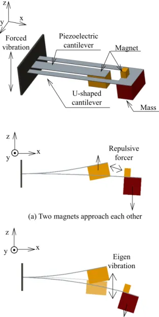
Walking vibration is unsuitable for vibration energy harvesting because of its low frequency (approximately 2.0 Hz). Therefore, we propose a noncontact double-frequency vibration system that uses magnetic force. A double-frequency vibration system is shown in Fig. 1. This system is composed of a piezoelectric cantilever and a U-shaped cantilever that is located around the piezoelectric cantilever. One magnet is attached at the edge of the piezoelectric cantilever, and the other magnet is set at the U-shaped cantilever. The U- shaped cantilever has a small eigen frequency because it has a small width and is heavy at the tip section. Thus, it vibrates at the eigen frequency. When the magnet on the U-shaped cantilever passes in front of the piezoelectric cantilever, it is bent by the magnetic force, as shown in Fig. 1(a). When the distance between the two magnets is large, the piezoelectric cantilever is free from the influence of the magnetic force. At this time, the piezoelectric cantilever vibrates at the eigen frequency as shown in Fig. 1(b). By repeating these actions, it is possible to continue to induce an eigen vibration in the piezoelectric cantilever. The piezoelectric cantilever receives a repulsive force in the opposite direction of the U-shaped cantilever as shown in the following equation:
where μ0 is the space permeability, m1 and m2 are the magnetic poles, F is the repulsive force, and r is the distance between the magnets. The piezoelectric cantilever is expected to be bent by this magnetic force.
22 1
0 r
m m πμ F 1
4 (1)
Double-Frequency Vibration Energy Harvester
We confirmed that the mono-morph piezoelectric cantilever was available for the energy harvest in the previous study 11). By vibrating the piezoelectric cantilever composed of a metal shim plate and a piezoelectric element, a voltage is generated. However, there are two problems that complicate high output power generation in this method.
The first problem is the dependence of the output power of the piezoelectric cantilever on its frequency characteristic. The output power of the piezoelectric cantilever depends on the deflection. Therefore, by vibrating the piezoelectric cantilever at the eigen frequency, high electric power is gained. However, the vibration frequency of human walking is significantly smaller than the eigen frequency of the piezoelectric cantilever. Therefore, if we apply a walking vibration to the piezoelectric cantilever directly, it does not resonate.
For this reason, high output power generation is difficult.
Another problem is the size limit of the piezoelectric cantilever. The output power of the piezoelectric element depends on the area; for high output power generation, upsizing of the piezoelectric cantilever is necessary. However, because this device is supposed to be used in vivo, it is difficult for the upsizing device to achieve high output power generation.
Thus, we propose the double-frequency vibration energy harvester, which induces an eigen vibration in the piezoelectric cantilever from human walking. By application of a magnetic force to the piezoelectric cantilever, it is possible to induce eigen vibration without abrading the cantilever. Furthermore, we propose a multi- morph piezoelectric cantilever that has multiple piezoelectric elements on the shim plate. By connecting each piezoelectric element in parallel, high output power generation is possible 13-15). Further, the strain of the piezoelectric element increases as the distance from the neutral axis of the cantilever is increased by lamination.
The output power of the piezoelectric element depends on its strain, and therefore high output power generation is possible by laminating the piezoelectric elements 16-18).
For these reasons, we aimed to develop a high-power vibration energy harvester using the double-frequency vibration system and the multi-morph piezoelectric cantilever.
'HVLJQRI(QHUJ\+DUYHVWHU 2.1 Double-frequency Vibration System
Walking vibration is unsuitable for vibration energy harvesting because of its low frequency (approximately 2.0 Hz). Therefore, we propose a noncontact double-frequency vibration system that uses magnetic force. A double-frequency vibration system is shown in Fig. 1. This system is composed of a piezoelectric cantilever and a U-shaped cantilever that is located around the piezoelectric cantilever. One magnet is attached at the edge of the piezoelectric cantilever, and the other magnet is set at the U-shaped cantilever. The U- shaped cantilever has a small eigen frequency because it has a small width and is heavy at the tip section. Thus, it vibrates at the eigen frequency. When the magnet on the U-shaped cantilever passes in front of the piezoelectric cantilever, it is bent by the magnetic force, as shown in Fig. 1(a). When the distance between the two magnets is large, the piezoelectric cantilever is free from the influence of the magnetic force. At this time, the piezoelectric cantilever vibrates at the eigen frequency as shown in Fig. 1(b). By repeating these actions, it is possible to continue to induce an eigen vibration in the piezoelectric cantilever. The piezoelectric cantilever receives a repulsive force in the opposite direction of the U-shaped cantilever as shown in the following equation:
where μ0 is the space permeability, m1 and m2 are the magnetic poles, F is the repulsive force, and r is the distance between the magnets. The piezoelectric cantilever is expected to be bent by this magnetic force.
22 1
0 r
m m πμ F 1
4 (1)
(a) Two magnets approach each other㻌
(b) Two magnets move away from each other
㻌
Fig. 1. Noncontact double-frequency vibration system that uses magnetic force.
2.2 Multi-Morph Piezoelectric Cantilever
The output power of the piezoelectric element depends on its capacitance. Moreover, the capacitance of the piezoelectric element depends on its area. Therefore, the larger the area of the piezoelectric element, the higher the output power that is generated. However, owing to the size limit of the energy harvester, it is difficult to achieve high output power generation. In this study, we propose a multi-morph piezoelectric cantilever that has multiple
piezoelectric elements on the upper and lower sides of the shim plate to enhance the energy harvester’s output power.
The schematic of the multi-morph piezoelectric cantilever is shown in Fig. 2. Previous studies have established that the output power of the piezoelectric power generator is improved by laminating the multiple piezoelectric elements. In the electric circuit, the piezoelectric element functions as a capacitor. Therefore, by connecting all the laminated piezoelectric elements in parallel, the overall capacitance of the device is defined by the following equation:
where Cp is the capacitance of the device, C1 to Cn are the capacitances of the laminated piezoelectric elements, and n is the number of laminated piezoelectric elements. Eq.
(2) shows that it is possible to increase the capacitance of the device by laminating the piezoelectric elements. With this, the multi-morph piezoelectric cantilever can generate high electric power. Besides, the output voltage of the piezoelectric element depends on the strain. The strain at a point on the cantilever is defined by the following equation:
where is the strain, y is the distance from the neutral axis of a point, and R is the radius of curvature. From Eq. (3), laminating results in eccentricity of the piezoelectric element relative to the neutral axis of the cantilever. For this reason, a high voltage is generated on the piezoelectric element, which is far away from the neutral axis of the cantilever. Hence, it is possible to improve the output power under the size constraint by laminating the piezoelectric elements.
In this study, the piezoelectric cantilever is fabricated by laminating the upper and lower sides of the SUS304 shim plate with polyvinylidene difluoride (PVDF), which is a piezoelectric polymer. We adopted the polyimide film as the insulator between each laminated PVDF in order to prevent energization. The
n 2
1
p C C C
C (2)
R
ε y (3)
U-shaped
cantilever Mass
Piezoelectric
cantilever Magnet Forced
vibration z y x
y x z
Repulsive forcer
y x z
Eigen vibration
3
thicknesses of each material are as follows: 40 m for PVDF and 7.5 m for polyimide.
Fig. 2. The schematic of the multi-morph piezoelectric cantilever.
2.3 Searching for Optimum Condition by Finite Element Analysis
In this study, we defined the permissible size of the energy harvester within 35.0 × 10.0 × 40.0 mm, which is based on the size of the general pacemaker 19). From this size limit, we determined the size of the U-shaped cantilever as 35.0 × 10.0 mm. Moreover, we employed SUS304 of 100 mm thickness as the U-shaped cantilever.
To ensure sufficient durability, we determined the widths of the U-shaped cantilever and the piezoelectric cantilever as 2.0 mm and 5.0 mm. In addition, we attached two neodymium magnets of 8.0 × 4.0 × 4.0 mm and 1.7 × 2.5 × 2.0 mm size to the piezoelectric cantilever and U-shaped cantilever. To induce eigen vibration of the U-shaped cantilever, it has a space of 5.0 mm at the tip section for attaching a mass. The mass attached to the tip of the U-shaped cantilever is made of brass, which has a large specific gravity. Now, the weight of the mass is related to the eigen frequency and the amplitude of the U- shaped cantilever. Therefore, the weight of the mass is a parameter that is related to the vibration characteristic of the U-shaped cantilever. Further, if the distance between the magnets of the piezoelectric cantilever and the U-
shaped cantilever is small, a large repulsive force is generated. In this case, the induced vibration of the piezoelectric cantilever is suppressed by the magnetic force. On the other hand, if the distance between the magnets is large, a small repulsive force is generated. In this case, the vibration of the piezoelectric cantilever is unlikely to be induced because of the small effect of the magnetic force. For these reasons, these values are important parameters in the device.
In this study, we searched for the optimum condition of the device by using ANSYS finite element analysis software. We set the design variables as the weight of the mass m, the piezoelectric cantilever length L, and the shim plate thickness of the piezoelectric cantilever t (100, 150, and 200 m). We searched for the optimum value of the weight of the mass and the cantilever length in two factors and three levels for each thickness of the shim plate. The physical property values of each material for vibration analysis are shown in Table 1. Analysis models of the U-shaped cantilever and the piezoelectric cantilever are shown in Fig. 3. First, we evaluated the vibration response of only the U-shaped cantilever model. We applied the walking vibration and the load that simulates the magnetic force to the analysis model of the U-shaped cantilever, and derived the time- varying displacement. From the vibration response of the U-shaped cantilever model, we calculated the time- varying magnetic force applied to the piezoelectric cantilever. After this, we applied the calculated magnetic force to the monomorph piezoelectric cantilever model and conducted a vibration analysis. From the results of the vibration analysis, we compared the average electric powers of the piezoelectric cantilever for 1.0 s at each condition. From the piezoelectric property, the output voltage of the piezoelectric cantilever is derived from the following piezoelectric equation:
where D is the electric flux density, d is the piezoelectric strain constant, T is the stress on the piezoelectric element,
T k mk ij mij
m d T ε E
D i, j, k, m=1, 2, 3 (4)
Piezoelectric cantilever
Unit:μm Poling direction
Poling direction
t 7.5 40
Piezoelectric element Insulator
SIM plate
Double-Frequency Vibration Energy Harvester
thicknesses of each material are as follows: 40 m for PVDF and 7.5 m for polyimide.
Fig. 2. The schematic of the multi-morph piezoelectric cantilever.
2.3 Searching for Optimum Condition by Finite Element Analysis
In this study, we defined the permissible size of the energy harvester within 35.0 × 10.0 × 40.0 mm, which is based on the size of the general pacemaker 19). From this size limit, we determined the size of the U-shaped cantilever as 35.0 × 10.0 mm. Moreover, we employed SUS304 of 100 mm thickness as the U-shaped cantilever.
To ensure sufficient durability, we determined the widths of the U-shaped cantilever and the piezoelectric cantilever as 2.0 mm and 5.0 mm. In addition, we attached two neodymium magnets of 8.0 × 4.0 × 4.0 mm and 1.7 × 2.5 × 2.0 mm size to the piezoelectric cantilever and U-shaped cantilever. To induce eigen vibration of the U-shaped cantilever, it has a space of 5.0 mm at the tip section for attaching a mass. The mass attached to the tip of the U-shaped cantilever is made of brass, which has a large specific gravity. Now, the weight of the mass is related to the eigen frequency and the amplitude of the U- shaped cantilever. Therefore, the weight of the mass is a parameter that is related to the vibration characteristic of the U-shaped cantilever. Further, if the distance between the magnets of the piezoelectric cantilever and the U-
shaped cantilever is small, a large repulsive force is generated. In this case, the induced vibration of the piezoelectric cantilever is suppressed by the magnetic force. On the other hand, if the distance between the magnets is large, a small repulsive force is generated. In this case, the vibration of the piezoelectric cantilever is unlikely to be induced because of the small effect of the magnetic force. For these reasons, these values are important parameters in the device.
In this study, we searched for the optimum condition of the device by using ANSYS finite element analysis software. We set the design variables as the weight of the mass m, the piezoelectric cantilever length L, and the shim plate thickness of the piezoelectric cantilever t (100, 150, and 200 m). We searched for the optimum value of the weight of the mass and the cantilever length in two factors and three levels for each thickness of the shim plate. The physical property values of each material for vibration analysis are shown in Table 1. Analysis models of the U-shaped cantilever and the piezoelectric cantilever are shown in Fig. 3. First, we evaluated the vibration response of only the U-shaped cantilever model. We applied the walking vibration and the load that simulates the magnetic force to the analysis model of the U-shaped cantilever, and derived the time- varying displacement. From the vibration response of the U-shaped cantilever model, we calculated the time- varying magnetic force applied to the piezoelectric cantilever. After this, we applied the calculated magnetic force to the monomorph piezoelectric cantilever model and conducted a vibration analysis. From the results of the vibration analysis, we compared the average electric powers of the piezoelectric cantilever for 1.0 s at each condition. From the piezoelectric property, the output voltage of the piezoelectric cantilever is derived from the following piezoelectric equation:
where D is the electric flux density, d is the piezoelectric strain constant, T is the stress on the piezoelectric element,
T k mk ij mij
m d T ε E
D i, j, k, m=1, 2, 3 (4)
Piezoelectric cantilever
Unit:μm Poling direction
Poling direction
t 7.5 40
Piezoelectric element Insulator
SIM plate
T is the permittivity of piezoelectric element, and E is the electric field on the piezoelectric elements. From the output voltage, the output power of the piezoelectric element is evaluated by the following equation:
where W is the output power of the piezoelectric element,
is the angular frequency of the piezoelectric cantilever, and V is the output voltage of the piezoelectric element.
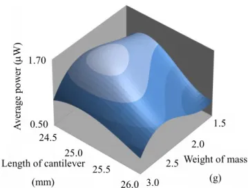
From the data constellation of the output power, we searched the optimum value of the weight of the mass and cantilever length at each thickness of the shim plate by employing the response surface methodology. In this study, we conducted a vibration analysis for each of the four conditions of m = 1.5, 2.0, 2.5, and 3.0 g, and L = 24.5, 25.0, 25.5, and 26.0 mm. The response surface at a thickness of 100 m for the shim plate is shown in Fig. 4.
At thicknesses of 100 and 150 m, electric power is maximum under the condition m = 2.4 g and L = 24.9 mm.
At a thickness of 200 m, electric power is maximum under the condition m = 2.3 g and L = 24.9 mm. At 100, 150, 200 m thicknesses, the optimum output power are 1.52, 0.42, and 0.17 W. The analysis shows that high electric power was found for a small thickness of the shim plate. This is caused by the large effect due to the difference of the strain on the piezoelectric cantilever. On the cantilever with a small thickness, high voltage was generated because a large strain was generated.
Accordingly, we fabricate a vibration energy harvester with a monomorph piezoelectric cantilever under the condition t = 100 m, m = 2.4 g, and L = 24.9 mm.
Moreover, the stiffnesses of PVDF and polyimide are significantly smaller than that of the SUS304 shim plate.
Because of this, there is a minuscule effect on the stiffness of piezoelectric cantilever due to the laminated PVDF.
For this reason, we fabricate a multi-morph piezoelectric cantilever using the shim plate of 100 m thickness, which gained maximum electric power with the monomorph type of cantilever.
Table 1. The physical property values of each material for vibration analysis.
(a) U-shaped cantilever
(b) Piezoelectric cantilever
Fig. 3. Analysis models of the U-shaped cantilever and the piezoelectric cantilever.
Fig. 4. Response surface at a thickness of 100 m for the shim plate.
pV2
C ω
W (5)
Material Young’s modulus (GPa)
Poisson’s
ratio Density (g/cm3)
SUS304 190.0 0.30 7.9
PVDF 2.0 0.30 1.8
Neodymium 17.0 0.28 7.5
Brass 110.0 0.34 8.5
Piezoelectric cantilever
Magnet U-shaped cantilever
Magnet
Mass
Weight of mass (g) Length of cantilever
(mm)
Average power (W)
0.50 1.70
24.5
26.0
1.5
3.0 2.5 25.0 2.0
25.5
5
3RZHU(YDOXDWLRQRI(QHUJ\+DUYHVWHU 3.1 Evaluation Experiment of Double-Frequency Energy Harvester
We fabricated a monomorph piezoelectric cantilever, applied vibration to the device with a vibrator, and evaluated the power generation performance of the device. A photo of the vibration energy harvester is shown in Fig. 5. The frequency conditions are 50.0 mm full amplitude and 2.0 Hz frequency, which are similar to the condition of walking vibration 20). We evaluated the power generation performance of the device by electric power measurement.
First, we derived the optimum load resistance value that obtains the maximum electric power from the piezoelectric cantilever. The device is represented by an equivalent circuit that has a current source and capacitor as shown in Fig. 6. From the circuit, the output power of the piezoelectric cantilever is maximum when the load resistance satisfies the following equation:
where RL is the optimum load resistance value. From Eq.
(6), the optimum load resistance of the monomorph piezoelectric cantilever is derived as 7.3 M. From the theoretical optimum load resistance value, we searched for the actual optimum load resistance value. We measured the output power at the load resistor with various load resistance values, and compared each power.
The output powers for the load resistances are shown in Fig. 7. As a result, the maximum power was obtained at a load resistance of 7.5 M. Therefore, we conducted a vibration experiment using a load resistor of 7.5 M at the monomorph piezoelectric cantilever. We compared the output powers of the double-frequency vibration system and the conventional system which is not attached the U-shaped cantilever. The output powers of each device are shown in Fig. 8. The double-frequency vibration system and the conventional system yielded 1.52 W and 0.16 W effective powers, respectively.
This result shows a 9.5 times improvement in the output power due to the double-frequency vibration system.
In addition, we measured the displacement of the piezoelectric cantilever with a laser displacement sensor.
From the measured displacement, we evaluated the vibration characteristic with fast Fourier transform (FFT) analysis. The eigen frequency of the piezoelectric cantilever is derived with the following equation 21, 22):
where kB is the flexural rigidity of the cantilever, m0 is the weight of the mass, mb is the empty weight of the cantilever, LC is the length of the cantilever, and f is the eigen frequency of the cantilever. From Eq. (7), the eigen frequencies of the piezoelectric cantilever and the U- shaped cantilever are derived as 25.9 and 8.7 Hz. The sampling frequency of the FFT analysis is 1000 Hz, and the results of the analysis are shown in Fig. 9. A peak is observed at a frequency of 25.4 Hz, which is close to the theoretical eigen frequency of the piezoelectric cantilever.
From this result, we confirmed that the device can induce the eigen frequency of the piezoelectric cantilever from the walking vibration. In addition, another peak is observed at a frequency of 8.8 Hz, which is close to the theoretical eigen frequency of the U-shaped cantilever.
This result shows that eigen vibration is induced in the U- shaped cantilever, and a load of 8.8 Hz frequency is applied to the piezoelectric cantilever by the magnetic force. Hence, we confirmed that the double-frequency vibration system functions effectively, and improves the output power of the device.
p
L ωC
R 1 (6)
3C 14033 b
0 B
L m m
k 3 π
2 f 1
)
(
(7)
Double-Frequency Vibration Energy Harvester
3RZHU(YDOXDWLRQRI(QHUJ\+DUYHVWHU 3.1 Evaluation Experiment of Double-Frequency Energy Harvester
We fabricated a monomorph piezoelectric cantilever, applied vibration to the device with a vibrator, and evaluated the power generation performance of the device. A photo of the vibration energy harvester is shown in Fig. 5. The frequency conditions are 50.0 mm full amplitude and 2.0 Hz frequency, which are similar to the condition of walking vibration 20). We evaluated the power generation performance of the device by electric power measurement.
First, we derived the optimum load resistance value that obtains the maximum electric power from the piezoelectric cantilever. The device is represented by an equivalent circuit that has a current source and capacitor as shown in Fig. 6. From the circuit, the output power of the piezoelectric cantilever is maximum when the load resistance satisfies the following equation:
where RL is the optimum load resistance value. From Eq.
(6), the optimum load resistance of the monomorph piezoelectric cantilever is derived as 7.3 M. From the theoretical optimum load resistance value, we searched for the actual optimum load resistance value. We measured the output power at the load resistor with various load resistance values, and compared each power.
The output powers for the load resistances are shown in Fig. 7. As a result, the maximum power was obtained at a load resistance of 7.5 M. Therefore, we conducted a vibration experiment using a load resistor of 7.5 M at the monomorph piezoelectric cantilever. We compared the output powers of the double-frequency vibration system and the conventional system which is not attached the U-shaped cantilever. The output powers of each device are shown in Fig. 8. The double-frequency vibration system and the conventional system yielded 1.52 W and 0.16 W effective powers, respectively.
This result shows a 9.5 times improvement in the output power due to the double-frequency vibration system.
In addition, we measured the displacement of the piezoelectric cantilever with a laser displacement sensor.
From the measured displacement, we evaluated the vibration characteristic with fast Fourier transform (FFT) analysis. The eigen frequency of the piezoelectric cantilever is derived with the following equation 21, 22):
where kB is the flexural rigidity of the cantilever, m0 is the weight of the mass, mb is the empty weight of the cantilever, LC is the length of the cantilever, and f is the eigen frequency of the cantilever. From Eq. (7), the eigen frequencies of the piezoelectric cantilever and the U- shaped cantilever are derived as 25.9 and 8.7 Hz. The sampling frequency of the FFT analysis is 1000 Hz, and the results of the analysis are shown in Fig. 9. A peak is observed at a frequency of 25.4 Hz, which is close to the theoretical eigen frequency of the piezoelectric cantilever.
From this result, we confirmed that the device can induce the eigen frequency of the piezoelectric cantilever from the walking vibration. In addition, another peak is observed at a frequency of 8.8 Hz, which is close to the theoretical eigen frequency of the U-shaped cantilever.
This result shows that eigen vibration is induced in the U- shaped cantilever, and a load of 8.8 Hz frequency is applied to the piezoelectric cantilever by the magnetic force. Hence, we confirmed that the double-frequency vibration system functions effectively, and improves the output power of the device.
p
L ωC
R 1 (6)
3C 14033 b
0 B
L m m
k 3 π
2 f 1
)
(
(7)
(a) Top view
(b) Side view
(c) Two magnets approach each other
(d) Two magnets move away from each other Fig. 5. Photo of the vibration energy harvester.
Fig. 6. An equivalent circuit that has a current source and capacitor.
Fig. 7. The output powers for the load resistances.
Fig. 8. The output powers of each device.
Fig. 9. The sampling frequency of the FFT analysis is 1000 Hz, and the results of the analysis.
U-shaped cantilever
Magnet
35
105
Piezoelectric cantilever
U-shaped cantilever
Piezoelectric cantilever
Magnet
Mass 5.0 mm
Eigen vibration
RL
Piezoelectri C
0.0 1.6 1.2 0.8 0.4
6.7 6.9 7.1 7.3 7.5 7.7 7.9 Load resistance (M)
Power (W)Power (W)
0.0 0.2 0.4 0.6 0.8 1.0 Time (s)
0.00 8.00 6.00 4.00 2.00
Double-frequency energy harvester Conventional device
0.0 10.0 20.0 30.0 50.0
Frequency (Hz) 0.0
0.8 0.6 0.4 0.2
Spectrum 8.8 Hz 25.4 Hz
40.0
7
3.2 Evaluation Experiment of Double-Frequency Energy Harvester
We fabricated a multi-morph piezoelectric cantilever with the shim plate having a thickness of 100
m, and evaluated the output power. In this study, we fabricated a bimorph piezoelectric cantilever that is laminated with one piezoelectric element on the upper and lower sides of the shim plate and a three-layered multi-morph piezoelectric cantilever that is laminated with three piezoelectric elements. To these cantilevers, we derived the optimum load resistance value from Eq.
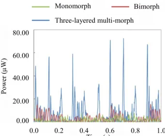
(6). Thus, the theoretical optimum load resistances of the bimorph and three-layered multi-morph type are derived as 3.6 and 1.9 M. As in the preceding section, we searched for the actual optimum load resistance for each type of piezoelectric cantilever. The bimorph and the three-layered multi-morph piezoelectric cantilever generated the maximum electric power at the load resistances of 3.6 and 2.1 M. The output powers of each type of piezoelectric cantilever are shown in Fig. 10.
Effective powers of 3.09 W and 6.68 W are gained from the bimorph and the three-layered multi-morph piezoelectric cantilever, respectively. This result shows a 4.4 times improvement in the output power by laminating with the piezoelectric elements. Moreover, we attached the device on a human’s chest, and conducted a vibration experiment with human walking. Electric power measurement of the three-layered multi-morph piezoelectric cantilever showed that as a result of the walking motion, 6.33 W of effective power was obtained. Now, the pacemaker’s power consumption is 1.0 W. The pacemaker operating for 24 hours will consume 86.4 mJ of electric energy in a day. The average daily walking time for a human is approximately two hours. Considering that the energy harvester generates during power only during walking, it generates 45.6 mJ electric energy with 6.33 W of output power. Thus, this device can supply 52.3% of the pacemaker’s power consumption. Hence, it is suggested that the vibration
energy harvester using a three-layered multi-morph piezoelectric cantilever can power the supply system for implant medical devices.
Fig. 10. The output powers of each type of piezoelectric cantilever.
(YDOXDWLRQRI3RZHU6WRUDJH&LUFXLW We designed a power storage circuit that stores the output voltage generated by the energy harvester.
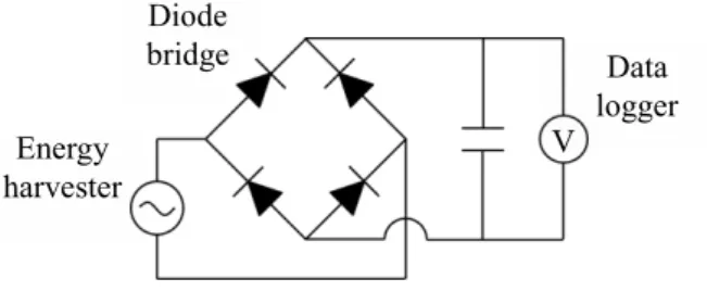
Because the piezoelectric element generates AC voltage, it is difficult to store the output voltage directly. Therefore, we propose a power storage circuit that rectifies the output voltage with a diode bridge. The power storage circuit is shown in Fig. 11. In this study, we adopted an electric double-layer capacitor that is suitable for sharp fluctuations of output voltage. We aimed to store 43.2 mJ electric energy from human walking for two hours. This target is half the pacemaker’s power consumption. First, we applied vibration to a three-layered multi-morph piezoelectric cantilever by human walking for one minute and evaluated the power storage performance by voltage measurement using a data logger. The result of the voltage measurement is shown in Fig. 12. Fig. 12 confirmed the increase in voltage over time. This result demonstrated rectification of the piezoelectric element’s AC voltage to DC, and power storage to the capacitor. In addition, we confirmed that the circuit can store 86.4 mV of output voltage in 1 min. From the voltage, we derived
0.0 0.2 0.4 0.6 0.8 1.0
Time (s) 0.00
80.00 60.00 40.00 20.00
Power (W)
Monomorph
Three-layered multi-morph
Bimorph
Double-Frequency Vibration Energy Harvester
3.2 Evaluation Experiment of Double-Frequency Energy Harvester
We fabricated a multi-morph piezoelectric cantilever with the shim plate having a thickness of 100
m, and evaluated the output power. In this study, we fabricated a bimorph piezoelectric cantilever that is laminated with one piezoelectric element on the upper and lower sides of the shim plate and a three-layered multi-morph piezoelectric cantilever that is laminated with three piezoelectric elements. To these cantilevers, we derived the optimum load resistance value from Eq.
(6). Thus, the theoretical optimum load resistances of the bimorph and three-layered multi-morph type are derived as 3.6 and 1.9 M. As in the preceding section, we searched for the actual optimum load resistance for each type of piezoelectric cantilever. The bimorph and the three-layered multi-morph piezoelectric cantilever generated the maximum electric power at the load resistances of 3.6 and 2.1 M. The output powers of each type of piezoelectric cantilever are shown in Fig. 10.
Effective powers of 3.09 W and 6.68 W are gained from the bimorph and the three-layered multi-morph piezoelectric cantilever, respectively. This result shows a 4.4 times improvement in the output power by laminating with the piezoelectric elements. Moreover, we attached the device on a human’s chest, and conducted a vibration experiment with human walking. Electric power measurement of the three-layered multi-morph piezoelectric cantilever showed that as a result of the walking motion, 6.33 W of effective power was obtained. Now, the pacemaker’s power consumption is 1.0 W. The pacemaker operating for 24 hours will consume 86.4 mJ of electric energy in a day. The average daily walking time for a human is approximately two hours. Considering that the energy harvester generates during power only during walking, it generates 45.6 mJ electric energy with 6.33 W of output power. Thus, this device can supply 52.3% of the pacemaker’s power consumption. Hence, it is suggested that the vibration
energy harvester using a three-layered multi-morph piezoelectric cantilever can power the supply system for implant medical devices.
Fig. 10. The output powers of each type of piezoelectric cantilever.
(YDOXDWLRQRI3RZHU6WRUDJH&LUFXLW We designed a power storage circuit that stores the output voltage generated by the energy harvester.
Because the piezoelectric element generates AC voltage, it is difficult to store the output voltage directly. Therefore, we propose a power storage circuit that rectifies the output voltage with a diode bridge. The power storage circuit is shown in Fig. 11. In this study, we adopted an electric double-layer capacitor that is suitable for sharp fluctuations of output voltage. We aimed to store 43.2 mJ electric energy from human walking for two hours. This target is half the pacemaker’s power consumption. First, we applied vibration to a three-layered multi-morph piezoelectric cantilever by human walking for one minute and evaluated the power storage performance by voltage measurement using a data logger. The result of the voltage measurement is shown in Fig. 12. Fig. 12 confirmed the increase in voltage over time. This result demonstrated rectification of the piezoelectric element’s AC voltage to DC, and power storage to the capacitor. In addition, we confirmed that the circuit can store 86.4 mV of output voltage in 1 min. From the voltage, we derived
0.0 0.2 0.4 0.6 0.8 1.0
Time (s) 0.00
80.00 60.00 40.00 20.00
Power (W)
Monomorph
Three-layered multi-morph
Bimorph
the output electric energy, and obtained a value of 0.4 mJ.
The circuit can thus store 0.4 mJ of electric energy by human walking for 1 min. Moreover, we derived the output electric energy in the case of walking for 2 h by the energy obtained for 1 min, and obtained 44.8 mJ. This value for the electric energy is higher than the target value.
Thus, we confirmed that the power storage circuit can store the device’s output effectively.
Fig. 11. The power storage circuit.
Fig. 12. Result of the voltage measurement.
&RQFOXVLRQV
In this study, we developed an energy harvester that generates electric power from human walking. This harvester combines a multi-morph piezoelectric cantilever and a double-frequency vibration system. We learned the following from this study:
・The eigen frequency of the piezoelectric cantilever was induced by low-frequency human walking.
・The double-frequency vibration system can increase the output power of the piezoelectric cantilever approximately 9.5 times compared to that of the
conventional system.
・The energy harvester with a three-layered multi- morph piezoelectric cantilever generated 6.33 μW of effective power from human walking, and therefore it can be used as the power supply system of implant devices.
We developed a power storage circuit that stores the electric power of the energy harvester effectively.
5HIHUHQFHV
1) C. Otto, A. Milenkovic, C. Sanders and E. Jovanov,
“System Architecture of a Wireless Body Area Sensor Network for Ubiquitus Health Monitoring”, Journal of Mobile Multimedia, 1, 307-326 (2006).
2) S. Choi, S.J. Song, H. Kim, J. Kim, J. Yoo and H.J. Yoo,
“A Low-power Star-topology Body Area Network Controller for Periodic Data Monitoring Around and Inside the Human Body”, Proc. of IEEE Conference on Wearable Computers, 139-140 (2006).
3) E. Jovanov, A. Milenkovic, C. Otto and P.C. Groen, “A Wireless Body Area Network of Intelligent Motion Sensors for Computer Assisted Physical Rehabilitation”, Journal of NeuroEngineering and Rehabilitation, 2[1], (2005).
4) A.D. Jurik and A.C. Weaver, “Remote Medical Monitoring”, Computer 41[4], 96-99 (2008).
5) B. Zhen, H.B. Li and R. Kohno, “Networking Issues in Medical Implant Communications”, International Journal of Multimedia and Ubiquitous Engineering, 4[1], 23-38 (2009).
6) M.R. Yuce, S.W.P. Ng, N.L. Myo, J.Y. Khan and W. Liu,
“Wireless Body Sensor Network Using Medical Implant Band”, Journal of Medical Systems, 31[6], 467-474 (2007).
7) M.A. Karami and D.J. Inman, “Powering Pacemakers from Heartbeat Vibrations Using Linear and Nonlinear Energy Harvesters”, Applied Physics Letters, 100[4], (2012).
8) A. Zurbuchen, A. Pfenniger, A. Stahel, C.T. Stoeck, S.
Vandenberghe, V.M. Koch and R. Vogel, “Energy Harvesting from the Beating Heart by a Mass Imbalance”, Annals of Biomedical Engineering, 41[1], 131-141 (2013).
9) J. Potkay and K. Brooks, “An Arterial Cuff Energy Scavenger for Implanted Microsystems”, Proc. of 2nd International Conference on Bioinformatics and Energy V
harvester Diode
bridge Data
logger
Time (s) 0.0
90.0
60.0
30.0
Voltage (mV)
0.0 10.0 20.0 30.0 40.0 50.0 60.0
9
Biomedical Engineering, ICBBE 2008, 1580-1583 (2008).
10) Y. Qi, N.T. Jafferis, K. Lyons Jr, C.M. Lee, H. Ahmad and M.C. McAlpine, “Piezoelectric Ribbons Printed onto Rubber for Flexible Energy Conversion”, American Chemical Society, 10[2], 524-528 (2010).
11) Y. Minami and E. Nakamachi, “Development of Enhanced Piezoelectric Energy Harvester Induced by Human Motion”, Proc. of IEEE International Conference on Engineering in Medicine and Biology Society, 1627- 1630 (2012).
12) H. Zhang, X.S. Zhang, X. Cheng, Y. Liu, M. Han, X. Xue, S. Wang, F. Yang, A.S. Smitha and H. Zhang, “A Flexible and Implantable Piezoelectric Generator Harvesting Energy from the Pulsation of Ascending Aorta: in Vitro and in Vivo Studies”, Nano Energy, 12, 296-304 (2015).
13) M. Liu, J. Tong, L. Wang and T. Cui, “Theoretical Analysis of the Sensing and Actuating Effects of Piezoelectric Multimorph Cantilevers”, Microsystem Technologies, 12[4], 335-342 (2006).
14) R. Andosca, T.G. McDonald, V. Genova, S. Rosenberg, J.
Keating, C. Benedixen and J. Wu, “Experimental and Theoretical Studies on MEMS Piezoelectric Vibrational Energy Harvesters with Mass Loading”, Sensors and Actuators A: Physical, 178, 76-87 (2012).
15) S.R. Anton, A. Erturk, N. Kong, D.S. Ha and D.J. Inman,
“Self-charging Structures Using Piezoceramics and Thin- film Batteries”, ASME 2009 Conference on Smart Materials, Adaptive Structures and Intelligent Systems, 85-96 (2009).
16) H. Mutsuda, K. Kawakami, M. Hirata, Y. Doi, and Y.
Tanaka, “Study on Wave Power Generator Using Flexible Piezoelectric Device”, ASME 2011 30th International Conference on Ocean, Offshore and Arctic Engineering.
American Society of Mechanical Engineers, 5, 267-273 (2011).
17) H.J. Xiang and Z.F. Shi, “Static Analysis for Multi- layered Piezoelectric Cantilevers”, International Journal of Solid and Structures, 45[1], 113-128 (2008).
18) S.L. Kok, N.M. White and N.R. Harris, “Free-standing Thick-film Piezoelectric Multimorph Cantilevers for Energy Harvesting”, Ultrasonics Symposium, 1977-1980 (2009).
19) T. Houzen, M. Takahashi, K. Saito and K. Ito, “Implanted Planar Inverted f-antenna for Cardiac Pacemaker System”, International Workshop on Antenna Technology: Small Antennas and Novel Metamaterials, 346-349 (2008).
20) V.T. Inman, H.J. Ralston and F. Todd, Human Walking, (Edwin Mellen Pr, New York, 1989).
21) D. Shen, J.H. Park, J. Ajitsaria, S.Y. Choe, H.C. Wickle III and D.J. Kim, “The Design, Fabrication and Evaluation of a MEMS PZT Cantilever with an Integrated SI Proof Mass for Vibration Energy Harvesting”, Journal of Micromechanics and Microengineering, 18[5], 1-7 (2008).
22) A. Erturk and D.J. Inman, Piezoelectric Energy Harvesting, (Wiley, New Jersey, 2011).