STUDY OF A ROCKFALL PROTECTIVE FENCE BASED ON BOTH EXPERIMENTAL AND NUMERICAL APPROACHES
著者 トラン バン プク
著者別表示 Tran Van Phuc journal or
publication title
博士論文要旨Abstract 学位授与番号 13301甲第3963号
学位名 博士(工学)
学位授与年月日 2013‑09‑26
URL http://hdl.handle.net/2297/37362
Creative Commons : 表示 ‑ 非営利 ‑ 改変禁止 http://creativecommons.org/licenses/by‑nc‑nd/3.0/deed.ja
1
Abstract
This study introduces a new type of rockfall protection fence made of posts, wire ropes, wire-netting and energy absorbers. The performance of this rock fence was verified in both experiments and dynamic finite element analysis. In collision tests, a reinforced-concrete block rolled down a natural slope and struck the rock fence at the end of the slope.Particularly, the performance of two types of energy absorber was investigated to determine the best energy absorber. In numerical simulation, a commercial finite element code having explicit dynamic capabili- ties was employed to create models of the two full-scale tests. To facilitate simulation, certain simplifying assumptions were adopted. Good agreement between numerical simulation and experimental data validated the numerical simulation. The results of numerical simulation provide a deeper understanding of the structural behavior of individual components of the fence during rockfall impact.
Additionally, a developed prototype of the fence is introduced. The cost-reducing modifications are increased post spacing and fewer wire netting layers. The numerical procedure again provides the nonlinear response of the prototype under various impact conditions. Furthermore, a simple but effective method of increasing fence resistance is developed from analysis. Finally, the practical application of two units of the prototype to protect a wide area is numerically investigated.
2
Chapter 1 Introduction
1.1 General Background
1.1.1 Rockfall Phenomenon
Rockfall is a rapid and rather spontaneous natural hazard that often occurs on steep slope, in which rock groups, or single rock blocks detached from the slope face fall down and maybe strike underlying infrastruc- tures.
In general, rockfall hazard is recognized as a complex function of rock blocks of mass, velocity, rotation and jump height, strongly depend on slope characterization and rockfall mechanics (Broili 1973).
1.1.2 Flexible Fences
Flexible fences are commonly employed to control or arrest falling rock blocks with the aim of protecting infrastructure. A flexible rockfall fence often consists of interceptive net, which directly intercepts falling rocks, and support structures of posts anchored to foundations or to competent bedrock, tieback and lateral ropes, energy absorbing devices, and anchors. The net panel must have been able to provide huge deformation to dissipate the kinetic energy of falling rocks with significant support of accompanied energy absorbers.
Compared with rigid barriers, flexible fences are often more cost-effective, and simpler in design. For these reasons, this kind of fence has been impressively developed for wide range of impact energy from 10 to 8000 kJ throughout the world.
1.2 Objectives and Scope of the Study
The main objective of this study is focus on rockfall protection with particular attention paid to developing of flexible fences. In this study, a new type of rock fence is shown to have a remarkable capacity to capture rocks and thereby prevent damage to transportations as well as fatalities. Basically, this fence was designed with an adequate stiffness without lateral guy cables and anchors. This basis makes the fence distinguishable from European styles.
This type of rock fence was scrutinized in both full-scale experiments and numerical simulation. In field tests, it has been the first time a reinforced-concrete (RC) block was actuated to roll down a natural slope and strike the fence erected at slope base without a navigation system.
Numerical simulation using the finite element code LS-DYNA reproduced the fence response against impact of the block, enabling to reach a deeper understanding of the structural non-linear behavior of the fence under severe dynamic condition.
Based on gained understanding of this kind of fence, a new prototype is developed. Above validated numeri- cal procedure was employed to clarify the response of the prototype to these structural alterations. Last but not least, this study also explored the performance of a fence comprising two units of the developed prototype, which is the most practical application suited to wide protection areas.
3
Chapter 2 Experiments on a Wire-Rope Rockfall Protective Fence
2.1 Introduction
In this study, a new type of rock fence made of posts, wire ropes, wire netting, and energy absorbers is intro- duced. To absorb a large amount of energy, the wire rope of the rock fence is semi-fastened to a post using an energy-absorbing device. Two types of energy absorber will be introduced and examined. This type of rock fence was examined in full-scale experiments carried out using a reinforced-concrete (RC) block that rolled down a natural slope without a navigation system.
2.2 Configuration of the Rock Fence
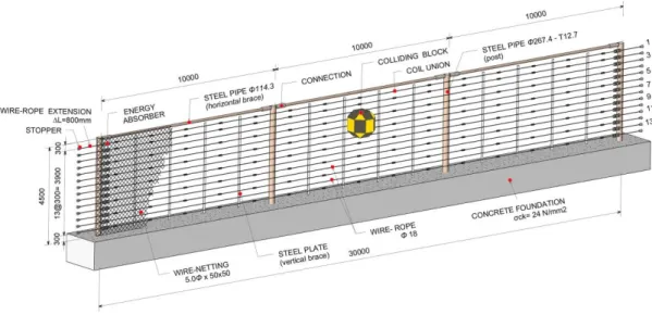
Figure 2.1 Configuration and dimensions of the rock fence (unit: mm)
Figure 2.1 shows the configuration and dimensions of the rock fence. Four posts made of concrete-filled steel tubes were vertically erected with a rigid joint on a concrete foundation, forming three spans with unequal length of 5, 8, and 5 m. Fourteen wire ropes were horizontally installed by connecting to both end posts via energy absorbers. Additionally, seven vertical braces of steel plates were installed at mid-span of the fence to help maintain the spacing between wire ropes. With the aim of supporting the wire ropes to catch rockfall, two layers of wire netting comprising 5-mm steel wire having grid spacing of 50 mm were used.
4
2.3 Outline of the Experiments
Two tests were carried out. The sole difference between the tests is that Type-A and Type-B energy absorbers were applied in Tests No. 1 and No. 2, respectively. The mass of the weight of 5.2 tons and its falling height were identical in the two tests. After Test No. 1, all components other than the posts were replaced with new ones. In the tests, the block began rolling from the peak of a slope at a height of approximately 37 m and then stuck the fence, which was located at the bottom of the slope.
2.4 Results of Rock Fence Tests
Figures 2.8 and 2.9 show the impact process; i.e., the motion of the RC block and the behavior of the rock fence just before and during the collision in Test No. 1 and Test No. 2, respectively, and the peak elongation of the wire netting. These images generally indicate that the fence could decelerate and captured the RC block in both tests.
Figure 2.2 Behavior of the rock fence (Test No. 1)
Figure 2.3 Behavior of the rock fence (Test No. 2)
However, in Test No. 1, rope breaking was observed (wire ropes No. 1 through No. 7 broke, as shown in Fig.
2.7) but there was no rope breaking in Test No.2.
Table 2.1 gives the magnitudes of the translational and rotational velocities and the corresponding impact en- ergies.
Table 2.1 Velocity and impact energy
Test No. Translation Velocity V
(m/s)
Rotation Velocity
(rad/s)
Translation Energy Ev
(kJ)
Rotation Energy Er
(kJ)
Total Energy E
(kJ)
1 16.0 14.3 666 140 806
2 16.8 16.8 734 193 927
5
2.5 Conclusion
This chapter presented experimental results for a newly developed rock fence able to vertically stand by itself without lateral guy cables and anchors. The fence was subjected to impact by an RC block rolling down a natural steep slope. The impact energy approximately estimated in two full-scale tests (having different shock absorbers) was about 900 kJ. The Type-B energy-absorbing device was found to be effective in preventing wire-rope breakage and in dissipating the impact energy of rockfall.
Chapter 3 Dynamic Finite Element Analysis on a Wire-Rope Rockfall Protective Fence
3.1 Introduction
This chapter presents a numerical procedure employed to reproduce two field tests on wire-rope rock fence as introduced in chapter 2 using the finite element code LS-DYNA. The numerical simulation was then useful for parametric analysis.
3.2 Numerical Simulation
The model used in the numerical simulation of the rock fence in Test No. 1 is referred to as Model No. 1 hereafter. Figure 3.1 illustrates the geometry of the wire-rope rock fence built in LS-DYNA, including the colliding block. The block is placed immediately next to the fence plane and assigned initial conditions of angular velocity, translational velocity in the Y direction (normal to the fence plane), and translational veloci- ty in the Z direction; these values were obtained from the results for Test No. 1.
Model No. 2 simulating Test No. 2 is similar to Model No. 1 on the whole with different initial conditions of the RC block obtained from the results in Test No. 2.
Figure 3.1 Technical sketch of the wire-rope rock fence built in LS-DYNA
3.3 Analysis, Validation and Discussion
3.3.1 Model No.1
Generally, the numerical Model No. 1 can almost simulate Test No. 1 in terms of the overall behavior, the wire-rope breakage, and the deformation of posts, horizontal braces, and vertical braces. There is however a
6
considerable difference between the test and the numerical model in terms of the number of broken wire ropes; i.e., 7 vs. 2.
3.3.2 Model No.2
Owing to the flexibility of the fence and the effectiveness of the Type-B energy absorbers, the amount of dis- sipated impact energy increased considerably, resulted in no breakage of the wire ropes, only little damage to the wire netting, and great effectiveness in catching the RC block. According to above points, it is obvious that the numerical simulation behavior of Model No. 2 agrees well with responses of the fence in Test No. 2.
3.4 Further Numerical Analysis
Numerical Model No. 2 was used in further numerical analysis with the aim of gaining a deeper understand- ing of the structural behavior of the rock fence. A parametric study was then executed.
3.4.1 Further Examination of the Wire Netting and Posts
Since the damage to the wire netting was mild in both Test No. 2 and Model No. 2, the second layer of wire netting seems to be somewhat redundant. To verify this point, two different versions of Model No. 2 were created with one layer of wire netting having a 50 × 50-cell or 150 × 150-cell grid. Numerical results indicat- ed that the rock fence could capture the RC-block in both cases, though the damage to wire netting was more severe in the latter case than in the former case.
Next, numerical results also shows that the post was entirely able to withstand the direct hit of the RC-block, which rolled up but did not bounce over the fence.
3.4.2 Energy Absorption Capacity of the Rock Fence
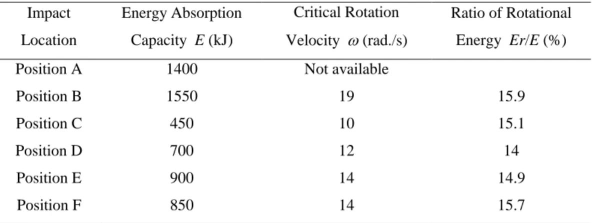
To survey the effect of the impact location on the energy absorption capacity of the rock fence, several mod- els were created by varying the impact location. These impact locations are indicated by the letters "A" to "F"
in Fig. 3.2. Table 3.3 shows that the resistance of the fence, not being uniform, strongly depends on the im- pact location.
Table 3.3 Energy absorption capacity of the rock fence according to six different points of impact Impact
Location
Energy Absorption Capacity E (kJ)
Critical Rotation Velocity (rad./s)
Ratio of Rotational Energy Er/E (%)
Position A 1400 Not available
Position B 1550 19 15.9
Position C 450 10 15.1
Position D 700 12 14
Position E 900 14 14.9
Position F 850 14 15.7
7
Figure 3.2 Map of impact locations (unit: mm)
3.5 Conclusion
In this chapter, numerical simulation using the finite element code LS-DYNA to model the rockfall collision in both Tests No. 1 and No. 2 was stated. Generally, the numerical results agree fairly well with the experi- mental results. Furthermore, they provide further insight into the responses of individual components and the fence as a whole. A thorough examination of how the position of the collision point affects the performance of the rock fence showed that the resistance of the fence greatly depends on the impact location.
Chapter 4 Prototype of a Wire-Rope Rockfall Protective Fence Developed with Three-Dimensional Numerical Modeling
4.1 Introduction
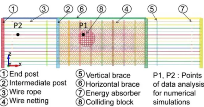
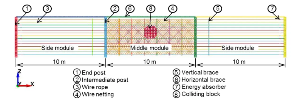
This chapter introduced a developed prototype of wire rope rock fence (abbreviated as WRF) with post spac- ing up to 10 m, assigned to all three modules as shown in Fig. 4.1. Additionally, only one layer of wire netting was used in the newly proposed prototype to reduce cost.
Figure 4.1 Schematic drawing of the developed prototype (unit: mm)
8
The numerical procedure was employed to examine the new prototype of the WRF. A simple but effective method was then introduced to improve the fence capacity. In addition, this study also explored the perfor- mance of a fence comprising two units of the developed prototype.
4.2 Description of the Developed Prototype
The configuration of the developed prototype as depicted in Fig. 4.1 is the same as that of the previous ver- sion of the prototype, except for the post spacing of 10 m and the number of wire netting layers (only one layer). And Type B energy absorber was employed in this prototype.
4.3 Numerical Analysis of the Developed Prototype
The numerical procedure proposed in the author’s previous work (Chapter 3) was used again to examine the developed prototype. Particular attention was paid to the effect of the location of impact on the fence’s re- sistance along with its causes. In particular, to the author’s knowledge, this study is the first to thoroughly examine the fence performance during an impact on the side module of the fence.
Figure 4.2 Technical sketch of the developed prototype built in LS-DYNA
Figure 4.2 built in LS-DYNA presents all constituent components of the developed prototype, whose numeri- cal parameters are given in Table 3.1.
Figure 4.3 Map of impacts on the middle module (unit: mm)
9
4.3.1 Numerical Analysis of the Functional Middle Module
This section presents numerical results of subsequent simulations of the functional middle module and dis- cusses the fence response under various impact conditions relating to the impact locations as shown in Fig.
4.3 and the size of the colliding block.
Table 4.1 presents that for all dimensions of the block, the fence resistance gradually increased along the line of impact points from A through D. This trend was unaffected by the block size. The table also shows that the fence resistance strongly depended on the size of the block, in that it gradually weakened as the block size decreased.
Table 4.1 Numerical results for fence capacity at different impact locations and various block sizes. Le: max- imum size D of block; Critical E: highest kinetic energy of a block that can be stopped by the fence.
Points Le = 1000 mm Le = 1200 mm Le = 1400 mm Critical E
(kJ)
vy
(m/s)
Critical E (kJ)
vy
(m/s)
Critical E (kJ)
vy
(m/s)
Point A 700 25.9 720 19.9 800 16.5
Point B 720 26.3 750 20.3 820 16.7
Point C 750 26.8 850 21.6 950 18.0
Point D 950 30.9 970 23.1 1100 18.9
Point E 400 19.7 400 14.9 400 11.6
Point F 800 27.8 900 22.4 1000 18.6
4.3.2 Numerical Analysis of the Functional Side Module
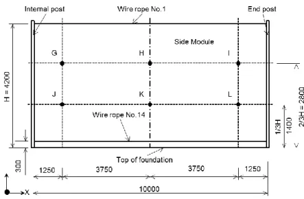
Figure 4.4 Map of impacts on the side module (unit: mm)
This section explores the performance of the fence with impacts on the side module. Similar to the analysis of the middle module, the fence response to impacts at various locations as indicated in Fig. 4.4 was investigated.
10
Table 4.2 reveals that the fence resistance remained unchanged at 700 kJ for impacts at points H, I, K, and L and the resistance to impacts on the side module was less than that to impacts on the middle module. This is attributable to the immense deformation of the end post, especially in the X direction.
Table 4.2 Numerical results of the fence resistance for different impact locations of the side module and block size
Point H I K L G J
Critical E (kJ) 700 700 700 700 850 1200 vy (m/s) 15.4 15.4 15.4 15.4 17.0 20.3
4.4 Enhancements of the Developed Prototype
By increasing AFF parameter (average friction force between wire rope and absorber) from 45 up to 60 kN helps reducing the fence elongation, therefore improving the fence capacity in catching the block. Indeed, with an AFF of 60 kN, the fence resistance for an impact at point A of the middle module increased to 950 kJ from an original value of 800 kJ corresponding to an AFF of 45 kN, which is a 19% increase.
More interestingly, the numerical result shows that the energy absorption capacity of the fence for an impact at point E of the middle module surprisingly increased from 400 for an AFF of 45 kN to 750 kN for an AFF of 60 kN, which is an increase of 87%. The improvement is considerable and suggests that the fence re- sistance is especially sensitive to the elongation of the wire ropes in this case.
4.5 Practical Application of the Developed Prototype
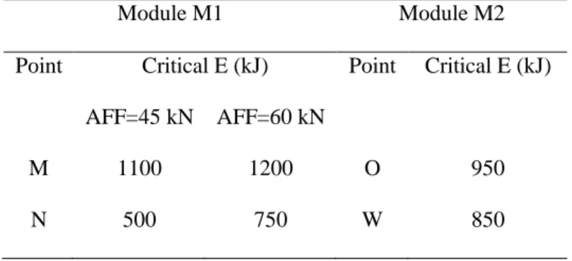
Table 4.3 Energy absorption capacity of a fence composed of two units of the developed prototype.
Module M1 Module M2
Point Critical E (kJ) Point Critical E (kJ) AFF=45 kN AFF=60 kN
M 1100 1200 O 950
N 500 750 W 850
Figure 4.5 Technical sketch of the model of two fence units erected side by side
In practice, the length of a site that needs to be protected commonly exceeds the prototype length (30 m). In this case, at least two units of the developed prototype must be erected side by side as shown in Fig. 4.5, and
11
the performance of the fence as a whole would change considerably; it is thus important to investigate this case. To carry out such analysis, iterative numerical models were calculated, and results for the energy ab- sorption capacity of modules M1 and M2 are presented in Table 4.3.
The numerical data summarized in Table 4.3 show a great increase in the fence resistance when two units of the prototype are placed side by side. Next, the enhancement approach of altering the AFF (from 45 to 60 kN) was applied to the joined fence units. The fence capacity increases considerably, as expected. The energy ab- sorption capacity of the fence increased to 1200 and 750 kJ for impacts at points M and N, respectively.
4.6 Conclusion
This chapter introduced a newly developed prototype of the WRF was introduced for mainly cost reasons, and the prototype was investigated employing a numerical procedure. The results provide insight into how the fence reacts to impacts under different conditions of impact location and block size.
A simple enhancement approach of altering the AFF parameter of energy absorbers was numerically demon- strated to be effective. Furthermore, the study considered the common situation in which a fence comprising two units of the prototype is required to protect a wide area, and the two-unit fence was found to be strength- ened using the proposed enhancement approach.
.
Chapter 5 Conclusion
This study focused on development of a newly flexible fence as one of the most effective protection approach against rockfall events. Distinguished from other flexible fences having been recently developed in Europe, the fence is able to vertically stand by itself without lateral guy cables and anchors. This characteristic makes the fence more suited to narrow protection sites, which are commonly seen in Japan.
In the way to deeply reach the nonlinear responses of the fence against rockfall, both approaches of full-scale tests and numerical simulation were conducted successfully. In particular, full-scale tests brought the most real behavior of the fence during rockfall impact, allowing access the actual way of how the fence would re- sponse against real rockfalls. As a powerful supplement to full-scale tests, numerical simulation using the commercial available program, finite element code LS-DYNA, was executed to reproduce the rockfall colli- sion in both Tests No. 1 and No. 2. In general, the numerical results meet fairly well with the experimental results. In addition, they provide further insights into the non-linear responses of individual components and the fence as a whole under dynamic conditions.
Next, a newly developed prototype of the wire-rope rock fence was introduced for mainly cost reasons, and the prototype was investigated employing above numerical procedure. The numerical results disclose in more details how the fence reacts to impacts under various conditions of impact location and block size. A simple but effective approach of fence performance improvement was also suggested. In addition, the common situa- tion in which a fence comprising two units of the prototype was numerically considered.
As a final remark, the emphasis here is that to accurately investigate and verify a rock fence subjected to rock- fall, the integration of full-scale tests and numerical simulation is the most relevant approach so far. Last but not least, numerical simulation is suited to any parametric study and is therefore useful for design or redesign work of similar type of rock fence.