630
IEICE TRANS. ELECTRON., VOL.E98–C, NO.7 JULY 2015
INVITED PAPER
Special Section on Microwave and Millimeter-Wave TechnologyDevelopment of Wireless Systems for Disaster Recovery Operations
Takashi HIROSE†a), Fusao NUNO††,Members,andMasashi NAKATSUGAWA††,Senior Member
SUMMARY This paper presents wireless systems for use in disaster recovery operations. The Great East Japan Earthquake of March 11, 2011 reinforced the importance of communications in, to, and between disas- ter areas as lifelines. It also revealed that conventional wireless systems used for disaster recovery need to be renovated to cope with technological changes and to provide their services with easier operations. To address this need we have developed new systems, which include a relay wireless system, subscriber wireless systems, business radio systems, and satellite communication systems. They will be chosen and used depending on the situations in disaster areas as well as on the required services.
key words: disaster recovery operation, business radio, subscriber wire- less system, satellite communications, the Great East Japan Earthquake
1. Introduction
The serious damage to communication infrastructures caused by the Great East Japan Earthquake and tsunami of March 11, 2011 knocked out public communication ser- vices. As a result, the services could not be provided until they were restored. The number of fixed-line services af- fected reached 1.5 million, and 4,620 base stations within the NTT Group went offthe air[1].
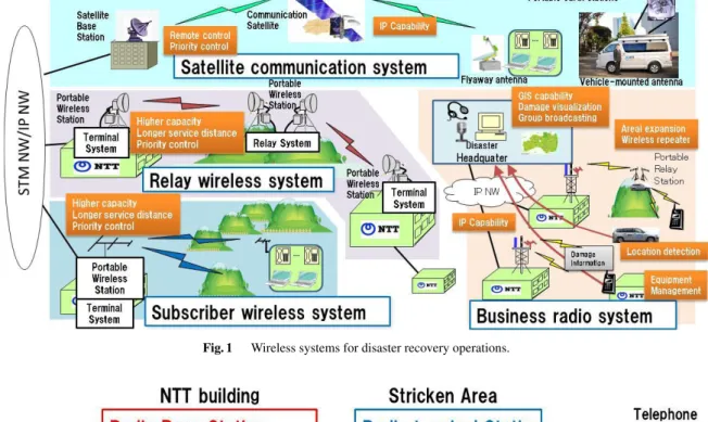
Wireless systems are useful for disaster recovery oper- ations because of their quick readiness in providing the ser- vices, which is attributable to the nature of “wireless.” Fig- ure 1 illustrates wireless systems for disaster recovery oper- ations. They are used to resume telecommunication services by temporarily substituting for damaged systems and/or by bridging the point to point(s) communications bypassing the cutoffrelay transmission lines.
Business radio systems are also used to provide com- munications for people doing restoration work through com- munication methods independent from damaged mobile and telecommunication lines.
Satellite communication systems are especially useful in disaster areas because of their wide coverage and the ease with which links can be established. The NTT Group’s protocols for restoring communications infrastructure in the event of a disaster such as the Great East Japan Earthquake and tsunami call for the use of satellite communication sys- tems to provide evacuation and disaster response centers with temporary lines of communication while optical fiber
Manuscript received April 3, 2015.
†The author is with NTT Network Technology Laboratories, NTT Corporation, Musashino-shi, 185–8585 Japan.
††The authors are with NTT Access Network Service Systems Laboratories, NTT Corporation, Yokosuka-shi, 239–0847 Japan.
a) E-mail: [email protected] DOI: 10.1587/transele.E98.C.630
and other transmission lines are being restored[2],[3].
For these reasons, NTT Group companies have intro- duced various wireless systems for disaster recovery oper- ations. However, even the newest system’s specifications were formulated back in 1995[4]. When using such obso- lete systems after the 2011 earthquake, we faced a number of problems regarding their capabilities and/or operations.
In order to address these problems, we started renovating the systems by incorporating present technologies into them so that they could provide better services[5]. The new wire- less systems for disaster recovery operations are presented in this paper.
2. Terrestrial Wireless Systems
Terrestrial wireless communications systems used for disas- ter recovery operations include relay wireless systems, sub- scriber wireless systems[6], and business radio systems[7].
After the 2011 earthquake it was found that certain features and functionalities needed to be added to their then-current capabilities. These included IP-based communications, in- creased capacity, aerial and communicable distance expan- sions, and priority and QoS controls. It was also found that information regarding the location of portable stations and equipment needed to be amassed, especially for business ra- dio so that locations and damage could be visualized. We have developed new systems to meet these requirements.
The new business radio and subscriber wireless sys- tems are introduced in detail in the following sections. They are expected to provide added capabilities for use in disaster recovery operations.
2.1 Subscriber Wireless System
Our new subscriber wireless system for disaster recovery operations is a major improvement over its predecessor, which only enabled networks to be switched to provide spe- cial public telephone service in disaster areas. The 2011 earthquake reminded us of the need to provide Internet capa- bility in addition to telephone service. The modulation tech- nology also needed to be changed from analog to digital[6].
The new system’s use of nonlinear distortion compensation technology narrowed the necessary bandwidth for a single channel from 640 kHz to 300kHz and increased the number of channels that could be used from 3 to 7. The increased number of available channels eases frequency reuse and en- ables the system to expand its service area through cyclical Copyright c2015 The Institute of Electronics, Information and Communication Engineers
Fig. 1 Wireless systems for disaster recovery operations.
Fig. 2 Composition example of Subscriber Wireless System.
Table 1 Typical system parameters.
use of the channels. The system adopts IP-based transmis- sion and QoS control technologies, which enable efficient sharing of the links between voice and web traffic. Table 1 summarizes typical system parameters. Figure 2 shows an example system configuration.
2.2 Business Radio System
Our previous business radio system was formulated in 1991 and used an analog modulation scheme. It could provide only voice communications between the control station and portable stations and among portable stations.
One of the most serious problems encountered during the Great East Japan Earthquake was the difficulty in con- tacting field workers who went to the stricken areas. It was also difficult to find information about the location of the tank lorries that were delivering fuel for emergency elec- tric power generators. At that time the commercial electric power source had been knocked out, so it was necessary to carry the fuel to the appropriate location. The unavailability
632
IEICE TRANS. ELECTRON., VOL.E98–C, NO.7 JULY 2015
Fig. 3 System Configuration example of Business Radio System.
Table 2 Typical system parameters.
Fig. 4 Photo of devices of Business Radio.
of the commercial power source had knocked out communi- cation facilities with resultant expanded damage[1].
The newly developed system has been digitalized to efficiently utilize frequency resources and has adopted IP technology[7]. Various new functions have also been added to it, such as gathering the location information of portable stations and displaying the locations on a map, broadcast- ing text messages to portable stations, and establishing com- munication either for a specific portable station or grouped portable stations. Table 2 summarizes typical system param- eters.
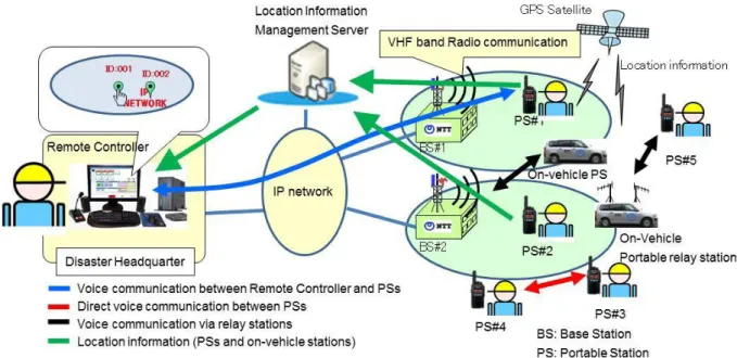
Figure 3 shows an example business radio system con-
figuration. The system comprises IP networks, base stations, portable stations, on-vehicle portable stations and portable relay stations, a remote controller and a location information management server. The locations of portable stations are detected through the use of GPS satellites. Figure 4 shows the devices that were developed for the system.
The system can provide three types of voice commu- nications. The first is voice communication between a re- mote controller and a specific portable station or grouped portable stations via IP networks and radio communications.
The second is direct voice communication between portable stations via radio communications. The third is voice com- munication by relay stations via radio communications.
A location information management server gathers lo- cation information of portable stations via IP networks and VHF band radio links. Then the location information of portable stations in the location information management server is shown in a remote controller in a disaster headquar- ter. So it is possible to send field workers to the appropriate location.
3. Satellite Communication System
Satellite communication systems are especially useful in disaster areas because of their wide coverage and the ease with which links can be established. Figure 5 shows an ex- ample configuration of a satellite communication system.
3.1 Motivation
The issues with our older satellite communication systems can be stated as follows.
-More than 15 years have passed since the systems were developed; this makes it difficult to effectively main- tain them.
Fig. 5 Satellite communication system in disaster recovery operations.
-The Portable Earth Station System antenna reflectors are large and thus difficult to carry to the disaster area. Fur- ther, they cannot easily be broken down into components and reassembling the components would take upwards of half an hour.
-The systems require hand operation for tracking the desired satellite; this makes tracking difficult and time con- suming (upwards of 15 minutes).
-Japanese radio regulations stipulate that radio opera- tors must be present during uplink access tests (which take upwards of 15 minutes).
-Azimuth, elevation, and polarization angle depend on the installation location; this has created a strong demand for automatic tracking of the desired satellite.
To address these issues, we have developed a new type of small earth station system and describe it in the following sections. We have developed three devices and one program as follows.
To offer terminal configurations suited to different kinds of disaster situations, we developed two different types of earth stations, a flyaway type and a vehicle- mounted type. The flyaway type is easy to carry to a dis- aster area because it can be dismantled and packed into four separate carrying cases, while the vehicle-mounted type can be installed in a normal-sized car capable of reaching the stricken area quickly to help restore communications.
Both stations can be up and running in about 15 minutes owing to the satellite auto-capture function (older systems needed about 60 minutes). These stations support transmis- sion speeds of up to 384 k bits/s for the return link, which can carry ten VoIP channels simultaneously.
The technologies that we developed are summarized in the following sections.
3.2 Flyaway Antenna
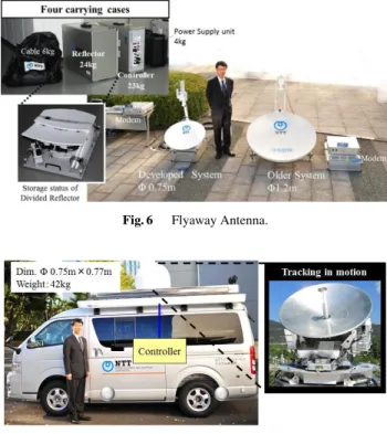
Our flyaway antenna is shown in Fig. 6. This antenna can easily be carried by hand into disaster areas that are inac- cessible by car or other means of transportation. We chose to use a 0.75 m reflector dish that can be dismantled and
Fig. 6 Flyaway Antenna.
Fig. 7 Vehicle Mounted Antenna.
packed inside a carrying case. Older reflector dishes were made of steel and very heavy. The new reflector dish is built of aluminum honeycomb and very light. The other parts can also be carried in cases, which greatly increases their porta- bility compared with existing devices. Moreover, no tools are needed for disassembly, packing, and reassembly and the automatic satellite capture function eliminates the need for operators to have special skills to set it up: setup can be finished within approximately 15 minutes.
A GPS receiver, an azimuth meter, and an attitude sen- sor are necessary for the automatic satellite capture function.
First, the antenna uses the GPS receiver to detect accurate location information, such as latitude, longitude and height.
It also uses a direction meter to detect direction. Then it cal- culates the azimuth direction, elevation, and polarization an- gle of the desired satellite. Detecting and calculating these values enables it to capture the desired satellite automati- cally.
3.3 Vehicle-Mounted Antenna
The vehicle-mounted earth station antenna that we devel- oped is shown in Fig. 7. This antenna is mounted on the roof of a vehicle and is suitable for use in disaster areas that are still accessible by vehicles. The dish diameter was re- duced to approximately 0.6 m to enable mounting even on ordinary cars. In addition to an automatic satellite capture function, it also has a function for automatically tracking satellites while the vehicle is moving. Antennas of this type are widely used in ships, but ours is considerably simplified, making it lighter in weight, lower in height, and less costly.
634
IEICE TRANS. ELECTRON., VOL.E98–C, NO.7 JULY 2015
Fig. 8 Procesure for remote uplink access test.
3.4 Simple Modem
If a disaster affects a wide area, a large number of earth sta- tions will need to be installed. However, there is a limit to the frequency range that can be used for satellite com- munications. Thus, to enable simultaneous use in as many places as possible, we have developed a modem with limited communication speed and frequency band for each earth sta- tion. This device uses the same transmission system as older satellite communication systems, and can thus be put to use with only minimal changes to the configuration and settings of existing base stations. By removing unnecessary func- tions and reducing the capacity to the minimum necessary, we were able to reduce the weight to one quarter and the size to one half of the older modem.
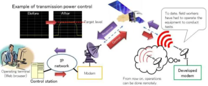
3.5 Remote Uplink Access Test Program
In older systems, an uplink access test is carried out after the earth stations have been installed but before they begin operations. This test is conducted through phone conversa- tions between technicians of the satellite operator and field workers to check that the antenna direction and power trans- mission levels are correct. Thus, in order to conduct these tests, the field workers need to be proficient in radio com- munication systems. However, in a large-scale disaster like the Great East Japan Earthquake of 2011, it can be difficult to assemble enough field workers with sufficient knowledge.
To make it easy for field workers without specialist knowl- edge to set up earth stations in the field, NTT Labs has de- veloped an uplink access test program that can be operated remotely from a control station. The procedure for conduct- ing this test remotely using this program is shown in Fig. 8.
3.6 Effectiveness of Developed Systems
Featuring improved portability, the flyaway antenna is easy to carry to a disaster area and can be set up without the need for any tools. The setup time is thus reduced from 30 min- utes to five minutes. After it is set up it can capture the desired satellite automatically. The time for capturing the desired satellite is reduced from 15 minutes to three min- utes. The antenna can be installed and ready for operation in less than 15 minutes including warm-up time, thus re- ducing installation time by nearly 25% compared with the
existing antenna. In addition, the use of a remote uplink test makes it unnecessary to send a radio operator to the instal- lation location.
The vehicle-mounted antenna is also easy to set up. Be- cause the antenna can track the desired satellite while the vehicle is in motion, communication can commence imme- diately when the vehicle arrives at a shelter in a disaster area.
4. Future Work
The experience of the Great East Japan Earthquake and tsunami reminded us of how critical electric power is in times of disaster. Although the current stations consume much less power than the older ones, power is still supplied by a generator with batteries used as a backup source. Ac- cordingly, it is necessary to develop more powerful batteries (such as fuel cells) and find further ways to reduce electric power consumption in systems for use in disaster recovery operations.
5. Conclusion
This paper described the NTT Group’s new wireless systems for disaster recovery operations, which have been designed to possess new and required capabilities. These capabilities will enable them to contribute in providing aid for disaster victims and system operators working to restore systems af- ter disasters. Cogently combining these systems in times of disaster will further enhance their effectiveness in recovery operations.
Acknowledgments
The authors wish to thank Mr. Hiroaki Kubozono and Mr.
Hirofumi Amano, former Head and current Head of NTT Access Network System Laboratories, for the enthusiastic encouragement they gave us as we pursued the development of the new systems.
References
[1] NTT NEWS RELEASE March 30, 2011.
http://www.ntt.co.jp/news2011/1103e/110330a.html
[2] T. Hirose, K. Ohta, Y. Imaizumi, and H. Yoshida, “Satellite Com- munication Systems Used in Disaster Recovery Operations,” IEICE Technical Report, SAT2011-57, pp.109–113, 2011.
[3] T. Hirose, T. Nakamura, Y. Shindo, and H. Yoshia, “ Wireless access systems used in disaster recovery operations after the Great East Japan Earthquake and tsunami,” ICC 12, 2012.
[4] K. Harada, T. Tashiro, Y. Yamashita, and T. Otsu, “Portable User Earth station for DYANET II,” B-226, The 1995 IEICE General Conference, 1995. (in Japanese)
[5] M. Nakatsugawa, F. Nuno, and T. Hirose, “Wireless Systems for Dis- aster Recovery Operations that Contribute for Quick Recovery from Large-Scale Disasters,” TK-4-3, The 2015 IEICE General Confer- ence, 2015. (in Japanese)
[6] K. Itokawa, F. Nuno, N. Tachikawa, F. Nagase, J. Iwatani, A.
Shinagawa, H. Yoshioka, T. Tsuchiya, and T. Shintaku, “Development and Field Trial Result of VHF Wireless System for Network Business Operation,” IEICE Technical Report, MW2014-142, pp.101–106,
2014. (in Japanese)
[7] F. Nuno, J. Iwatani, F. Nagase, and K. Itokawa, “Wireless System for Network Business Operation and Communicaiton quality,” BI-5- 4, The 2015 IEICE General Conference, 2015. (in Japanese)
Takashi Hirose received the B.E. and M.E.
degrees in Mechanical Engineering from Keio University in 1988 and 1991. He joined NTT Telecommunication Networks Laboratories in 1991. Since then, he has been engaged in re- search of personal communication systems and development of a routing system for the asym- metrical satellite internet communication sys- tem. He is currently a senior research engineer, supervisor in NTT Network Technology Labo- ratories, working on the next generation access network systems.
Fusao Nuno received his B.E. degree from Ehime University in 1991, his M.E. degree from Kumamoto University in 1993, and his Ph.D.
degree from Kyoto University in 2014. In 1993, he joined NTT and engaged in research and de- velopment of portable terminals and base sta- tions for broadband wireless access systems. He is currently a senior research engineer in NTT Access Network Service Systems Laboratories and engaged in the development of a wireless system for network business operations.
Masashi Nakatsugawa received the B.E.
and M.E. degrees from Waseda University in 1987 and 1989, and the M.S. degree from the California Institute of Technology, USA, in 1999. He joined NTT Radio Communication Systems Laboratories in 1989. His research ex- periences include MMIC circuit design, pack- aging technology, software defined radio, and wide-area wireless access systems. From 2010 to 2012, he was a senior manager at Radio Divi- sion, Technical Planning Department, NTT. He is currently engaged in R&D of wireless access and wireless backhaul sys- tems. He received the 1996 Young Engineer Award from the IEICE and the YRP Award from the YRP R&D Promotion Committee in 2002. He is a member of the IEEE and the Japan Society of Applied Physics.