Japan Advanced Institute of Science and Technology
JAIST Repository
https://dspace.jaist.ac.jp/
Title 液体電極プラズマ発光分光分析法を用いた長期間測定
のための方法
Author(s) Ruengpirasiri, Prasongporn Citation
Issue Date 2019‑09
Type Thesis or Dissertation Text version ETD
URL http://hdl.handle.net/10119/16191 Rights
Description Supervisor:高村 禅, 先端科学技術研究科, 博士
Methods for Long Time Monitoring Using
Liquid Electrode Plasma Optical Emission Spectrometry
Abstract
Doctor of Science (Materials Science) Takamura Laboratory 1620442 Prasongporn RUENGPIRASIRI
Part 1: Research Content
Background: Liquid electrode plasma (LEP) driven by alternating current (AC) is used as an excitation source for elemental analysis. LEP forms in a vapor bubble generated inside a narrow-center microchannel by using high-voltage power. This technique can detect metals with high sensitivity and high selectivity. More recently, we found the better conditions to generate LEP by alternating current with higher stability and significantly low damages on microchannel, called the new method as AC- LEP. In this plasma, an air bubble remained in the LEP channel during plasma generation by AC power source. The bubble is expected to affect plasma generation strongly. In order to investigate in detail the effect of the bubbles, we fabricated a microfluidic system to introduce different kinds of gas bubbles intentionally into the LEP channel. In AC-LEP, significantly less channel damage (1/3000) was reported compared to direct current LEP (DC-LEP) [1]. The plasma was continuously generated in a poly(dimethylsiloxane) (PDMS) chip for about 10 min without severe channel damage or expansion.
These observations indicated that AC-LEP showed great potential for reducing channel damage, although the mechanism of this improvement was not clear. In order to increase detection efficiency, electrochemistry is one of an attractive method for preconcentration of heavy metal. Depending on the nature of analytes and sample matrix, electrochemical detection (ECD) is very sensitive and can be detected in the femtomole L-1 (10-15 M) range. A more chemical-specific detection condition can be acquired by selecting the suitable applied voltage for the oxidation and reduction potential and working electrode materials. Target compounds (analytes) are separated using a specific voltage in reduction reaction process. After separation, the compounds present at working electrode will be directly desorption and detection by using LEP.
Aim: In this study, various types of gases were introduced intentionally from outside into the AC- and DC- LEP and their effects on plasma generation and channel damage were investigated. For that purpose, a new chip design for the introducing gas into the channel was developed. Channel damage was compared in both DC-LEP and AC-LEP with and without gas introduction. Moreover, the combination of two techniques for heavy metal detection was studied. With the aid of deciding on the excellent utilized voltage for the oxidation/reduction potential and properties of the working electrode, an extra selectivity of detecting condition can be acquired.
Experimental:
1. Development of the liquid electrode plasma (LEP) chip with gas introduction
The PDMS layer is attached onto a glass slide that is a substrate for the chip. The channel is carved on the PDMS sheet by a photolithographic technique. There are two inlets, liquid inlet and gas inlet, and one outlet on the chip. The width and depth of the channel on PDMS sheet is determined by the height of photoresist patterned on silicon wafer. Two 2-mm diameter holes were punched at each end of the LEP channel. Finally, the PDMS layer and the substrate are bound together by oxygen plasma. Both liquid and gas were pushed by syringe pumps with same flow rate and then observed with microscope.
Types of selected gases in this work are Ar gas, nitrogen gas, oxygen gas and air.
2. Study on effect of introduced gas bubbles for the low channel damage in direct and alternating current liquid electrode plasma atomic emission spectrometry
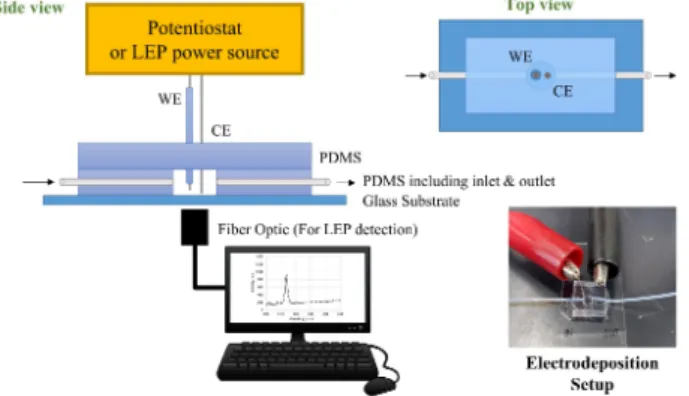
For LEP determination, chip was fixed in the experimental setup shown in Fig. 1. Both platinum electrodes were connected to either a DC or AC power source. Syringe pumps were used to introduce sample solutions and gas. AC-LEP was generated using a specially designed power-controllable AC power source. A DC power supply was used for DC-LEP. The plasma was observed with an optical microscope and a UV-VIS spectrophotometer. The chip dimension was observed using a digital microscope. For fair comparison of channel damage, both AC-LEP and DC-LEP conditions were optimized to give the same signal intensity (limit of detection, LOD) for Pb in 0.1 M nitric acid. To obtain same LOD in all cases, the optimized conditions were used, and channel damage was evaluated as a function of plasma duration. Microscopy images were obtained from after first applied voltage for 10 measurements (interval time of 10 s) and then the channel width was measured and compared.
Figure 1 Experimental setup
3. Design of microchip for metal detection by electrodeposition coupled with LEP-OES The reaction chamber was fabricated by PDMS and glass substrate. After PDMS sheet fabrication, 3-mm diameter hole was punched on 1 cm2 PDMS sheet. Glass substrate was cleaned prior bonding with PDMS.
Then, oxygen plasma treatment was used for bonding PDMS onto substrate and covered with other PDMS layer. Working electrode and counter electrode are platinum wire with 0.3 mm diameter. For working electrode, PDMS was coated except for the area that will use for analyte deposition. For efficiency comparison, Au wire was selected to be working electrode with same fabrication and usage. The reaction chamber is shown in Fig. 2. Below the chamber, fiber optic was applied to obtain the detection signal after electrodeposition. In the LEP detection step, DC-LEP with 200-1500 V of applied voltage with 0.5 msec on- time and 2 msec off-time was applied for 20 cycles. Analyte model in this study is 50 ppm Pb in nitric acid and HMImBr. For the characterization of electrodeposition of target heavy mental, Energy Dispersive Spectrometer (EDS) attachment for scanning electron microscope for chemical analysis was performed.
Electrodeposition was achieved by using Potentiostat.
Figure 2 Reaction chamber and experimental setup for heavy metal detection by electrodeposition coupled with LEP-OES
Part 2: Research Purpose Results and Discussion:
1. Development of the liquid electrode plasma (LEP) chip with gas introduction
The bubble was formed after passing through the intersection, which was matched with previous studied.
For smaller gas channel size, the gas was hard to divide into small bubbles. On the other hand, when gas channel size was bigger, it became quite hard to push out the gas especially with small liquid channel size.
Because of the pressure of gas and liquid inside of channel was different, the flow rate of gas and liquid must be optimized to achieve the suitable pressure condition for reproducible bubble generation. To compare the effect of type of introduced gas, Ar gas, nitrogen gas, oxygen gas, and air were selected. At the same analyte concentration, Air introduction system shown the relatively high peak area with low standard deviation.
While, without gas introduction shown lower peak area with relatively satisfy standard deviation. This is one of benefits of AC–LEP usually provide stable and reproducible signal intensity.
2. Study on effect of introduced gas bubbles for the low channel damage in direct and alternating current liquid electrode plasma atomic emission spectrometry
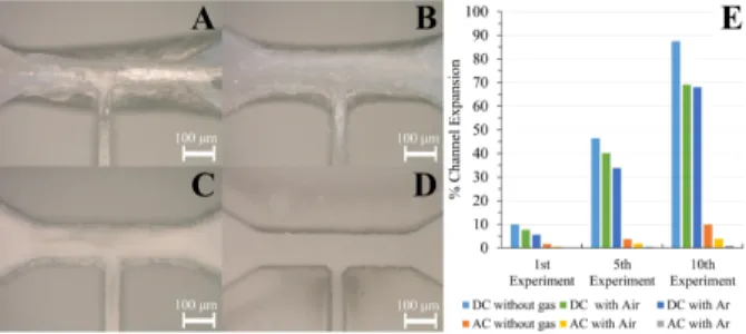
Figure 3 compares channel damage when different gases were introduced during DC-LEP and AC-LEP. The DC-LEP samples (Fig. 3A and B) showed less channel damage when gas was introduced. As before, the AC-LEP (Fig. 3C and D) samples showed much less channel damage than the DC-LEP ones, where the least damage was observed when argon gas was introduced. Figure 3E summarizes the volume percentage of channel expansion with and without gas introduction. There was an obvious difference between the huge channel expansion of the DC-LEP sample and small channel expansion of the AC-LEP sample, with Ar gas introduced. In the case of DC-LEP, the plasma generated after Joule heating creates vapor bubbles and some time is required to remove remaining products from previous plasma generation; the pulses of the applied DC power may not correspond with the times when the introduced bubbles are present. Synchronization of applied voltage and bubble generation will allow lower power (lower applied voltage) to generate plasma than in case of bubble generation from Joule heating. Therefore, the channel damage did not reduce significantly in the case of DC-LEP with gas introduction. In contrast, the AC power source can be applied continuously for a longer period compared to the DC source; hence, the generated bubbles are expected to remain inside the narrow channel for a longer period, stabilizing the plasma. Hence, introduction of bubbles could greatly facilitate plasma generation.
Figure 3 Optical microscopy images of chips used under different condition. (A) DC-LEP with air, (B) DC-LEP with Ar, (C) AC-LEP with air, and (D) AC-LEP with Ar. (E) Comparison of channel expansion in DC-LEP and AC-LEP during the different experiments.
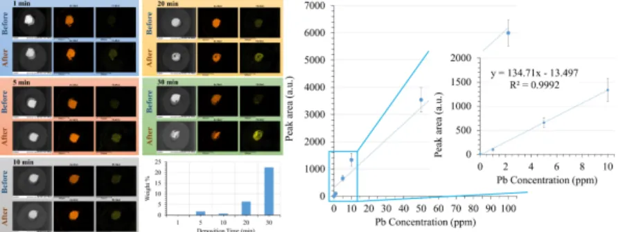
3. Design of microchip for metal detection by electrodeposition coupled with LEP-OES Longer deposition time will provide higher time of reduction of analyte on the working electrode. From Fig.
4, the amount of deposited Pb was increase when deposition time is increase. At 30 minutes of deposition time showed the highest amount of deposited Pb. After that, LEP was performed to observe the dissolution of Pb from electrode. The result showed the consistent tendency with the found Pb on electrode. The highest peak area came from the electrode that found highest Pb. We can conclude that the optimum condition for
these couple technique are Au wire as working electrode and solution was prepared from 0.1 M HMImBr.
The linear dynamic range from this calibration curve is 0 – 10 ppm of lead concentration. Within linear range, peak area is directly proportional to the lead concentration and illustrates satisfied linear regression (R2 = 0.9992). The detection limit (LOD) of this system is 0.0279 ppm of lead.
Figure 4 (Left) EDS images of Au-WE before and after Pb deposition and elemental mapping of Au (as WE) and Pb. Graph shown percentage of deposited Pb on electrode surface. (Right) Analytical
performance of electrodeposition coupled with LEP-OES of 0 – 100 ppm of lead in 0.1 M HMImBr.
Conclusion: In this study, an elemental analyzer based on LEP-OES for long time environmental monitoring has been successfully investigated. The effects of external gas introduction into AC-LEP and DC-LEP were studied. In both case of AC-LEP and DC-LEP, the external gas bubbles facilitated stable and high sensitive plasma generation with lower power, which result in reducing channel damage and increasing the lifetime of the analysis chip. These effects are significant in Ar introduction and AC-LEP case. The power for homogeneous nucleation of bubble in conventional DC-LEP is higher than that required for plasma generation, resulting in high channel damage. To overcome of drawbacks of both methods, an elemental analysis based on electrodeposition integration with LEP-OES has been realized. We investigated suitable deposition potential, solution system and WE materials could maintain high stable plasma and improve intensity of deposited heavy metal ions. This system is allowed to monitoring heavy metal for a long time and continuously.
References: [1] K. Do Van, M. Hidekazu, Y. Tamotsu, T. Phan Trong, O. Akitoshi, T. Yuzuru,
Development of AC-driven liquid electrode plasma for sensitive detection of metals, Jap J Appl Phys, 55 (2016) 02BC23.
Keywords: Liquid electrode plasma, Electrodeposition, Elemental analysis Part 3: Research Accomplishment
Publication: P. Ruengpirasiri, P. T. Tue, H. Miyahara, A. Okino, Y. Takamura, Study on effect of introduced gas bubbles for the low channel damage in Direct and Alternating Current Liquid Electrode Plasma Atomic Emission Spectrometry. 2019. Jpn. J. Appl. Phys. 58, 097001.
Conferences:
1. P. Ruengpirasiri, P. T. Tue, A. Okino, H. Miyahara, Y. Takamura, Improvement of channel damage and its mechanism in alternating current liquid electrode plasma atomic emission spectrometry, The Twenty Second International Conference on Miniaturized Systems for Chemistry and Life Sciences (µTAS 2018), Kaohsiung, Taiwan, November 11-15, 2018. (Including peer review)
2. P. Ruengpirasiri, P. T. Tue, H. Miyahara, A. Okino, Y. Takamura, Investigation of the mechanism of low channel damage in AC-LEP by gas introduction, The 79th JSAP Autumn Meeting, Nagoya, September 18-21, 2018. (Including peer review)
3. P. Ruengpirasiri, P. T. Tue, Y. Takamura, Study of the mechanism of low channel damage in AC- LEP by gas introduction, 37th CHEMINAS, Ibaraki, May 21-22, 2018. (Including peer review) 4. P. Ruengpirasiri, P. T. Tue, A. Okino, H. Miyahara, S. Tatsumi, T. Yamamoto, Y. Takamura, Effect
of introduced bubbles to the generation of liquid electrode plasma by alternating current power source, The 78th JSAP Autumn Meeting, Fukuoka, September 5-8, 2017. (Including peer review)