Study on Crack Patterns of a Reinforced
Building
著者
PERALTA Raquel. Maria, TOKUHIRO Ikuo
journal or
publication title
鹿児島大学工学部研究報告
volume
34
page range
73-95
別言語のタイトル
鉄筋コンクリート造建物のひび割れ性状に関する研
究
URL
http://hdl.handle.net/10232/11545
Study on Crack Patterns of a Reinforced
Building
著者
PERALTA Raquel. Maria, TOKUHIRO Ikuo
journal or
publication title
鹿児島大学工学部研究報告
volume
34
page range
73-95
別言語のタイトル
鉄筋コンクリート造建物のひび割れ性状に関する研
究
URL
http://hdl.handle.net/10232/00012689
PERALTA. Raquel. Maria and TOKUHIRO Ikuo
(Received May 31, 1992)
Abstract
The present work results from the observation of some crack patterns, which occurred in several
construction elements of a reinforced concrete building located in the Sakurajima area. The following two studies were made:
(I )-The crack patterns produced in the largest slab of second floor.
The causes of the cracks in the slab were analyzed on the basis of four specific considerations of
Japanese method of calculation (AIJ:Architectural Institute of Japan) and of German method of
calculation (DIN), for reinforced concrete buildings:
(a)-The thickness of the slab.
(b)-A determination of the required area of steel, which was calculated from the bending moment of
the slab.
(C)-A comparison between the calculated fiber tensile stress of the concrete and the allowable tensile
stress of concrete.
(d)-Bond stress and shear stress.
(II) -The crack patterns were caused by a differential subsidence of some foundation components.
RESUMEN
El presente trabajo ha sido realizado a partir de la observacion de la fisuracion producida en diferentes elementos constructivos de un edificio construido en hormigon armado ubicado en el area del Sakurashima.
Los siguientes dos estudios fueron realizados:
(I) La fisuracion producida en la mayor losa perteneciente al segundo piso.
Las causas de la fisuracion de la losa fueron analizadas en base a cuatro especificas consideraciones del metodo de calculo japones (AIJ, Instituto de Arquitectura del Japon) y de acuerdo al metodo de calculo aleman (DIN), para edificios de hormigon armado:
(a) El espesor de la losa.
(b) Determinacion de la cuantia de acero necesaria, la que fue calculada a partir de los
momentos flectores de la losa.
real y la resistencia admisible a la traccion del hormigon.
(d) Tension de adherencia entre el hormigon y el acero; tension de corte del hormigon.
(II) La fisuracion originada a partir del descenso diferencial entre algunos componentes de la
fundacion del edificio.
L
E 9r
L
E 9r
+
4— -H-" + +-FIRST FLOORFig. 1 First floor and basement
s | u_ * | " | o 2 fTTT
*
•>f
6 o .35. 205* 1 I-f^"
Fig. 2 Second floor plan
SECOND FLOOR
H-•>
f"
200 .35. TT "TJ
E 91
L
E 9r
L
E 9r :i
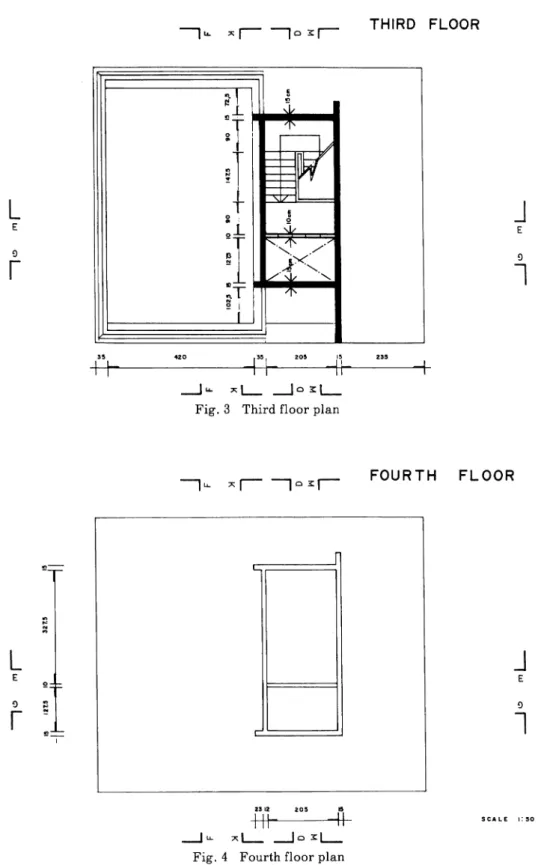
Fig. 3 Third floor plan
~~I" *l l°2l— 1—.. r 23 12 205 IS
T+l
W-| u. x| lo^lFig. 4 Fourth floor plan
THIRD FLOOR
j
E 91
FOURTH FLOORJ
E 91
SCALE i : s oSECTION GG
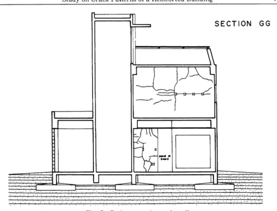
Fig. 5 Crak pattern in north wall
SECTION FF
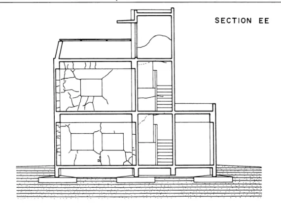
SECTION EE
I
11
i n
n
iXVk
S . C
3 pII
U
_U
Fig. 7 Crak pattern in south wall
SECTION KK
7 )
/^S
rY4_
~\
SEC1
_l
••• • \fc 1
'
r^-K^-Fig. 9 Crak pattern in interior wall
SECTION MM
I -(a) THICKNESS OF THE SLAB
According to AIJ, the minimum value of slab thickness is shown in the next table:
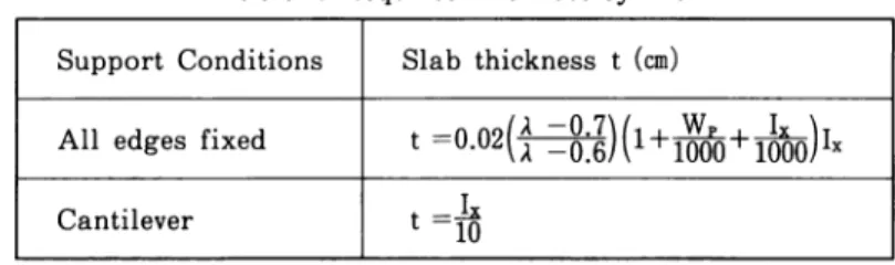
Table 1. Required thickness by AIJ Support Conditions Slab thickness t (cm)
All edges fixed
t -o.o2(A -o.ejr+iooo+iooo)1*
Cantilevert - i
t "10being in this case:
A =jgY/jgx = 1.59
£x = effective span length in the short direction=420 cm £Y = effective span length in the long direction=670 cm
WP = sum of live load and weight of finishing (kg/nf) =372.7 kg/nf (see Table 3)
For the study of Slab 1 of second floor, corresponds to apply the first case of Table 1, it is:
1=°-02(Tf^i)(1+iSbz+S)x420=13-5a»
The real thickness of slab is 15 cm, which means that for AIJ, it is appropriate for the assumed load.
The thickness of slabs, according to DIN is defined by a simplificated verification of the slender ness to flexion.
The limit of slenderness j^i/h of elements submitted to flexion, can not be larger than the value 35,
jg,/h<or=35
P = short span length of slab.
a = itj it coefficient that depends on the kind of supports system (To see Table 2) h = t , thickness of slab
35 = number fixed by the standard
When the slab support the walls loads directly, the slenderness must be: 4/h<or = 150/4
150=number fixed by the standard
£t = a X £ , for bent elements whose deflections are mainly originated by the acting load on
the span. For the case in study, it is:
£ =4.20m 4/11=4.2/0.15 = 28
a = 1 (see point c)
4/h<or=35
4.20/0.15<35, then 4.20/35<0.15
28^35 0.12^0.15
A"
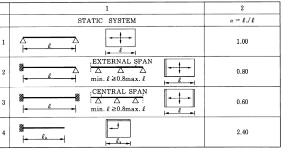
Table 2. Values a for different support systems.
1 STATIC SYSTEM "A 7\ h H : EXTERNAL SPAN
hs—s—^
min. jg ^0.8max. £ : CENTRAL SPAN•i
h£—£—El
H
min. jg ^0.8max. £
^JI" ^
-I
a = £j£ 1.00 0.80 0.60 2.40I -(b) DETERMINATION OF REQUIRED AREAS OF STEEL AND MAXIMUM MOMENTS
OF THE SLAB According to AIJ: » 3cm MORTER 60 Kg/ m cm SLAB
ACCESSORIES 8Kg/m2
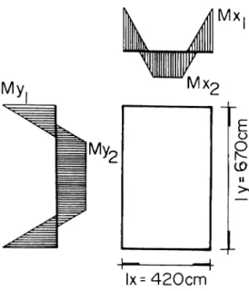
• 0.9cm ACUSTIC ABSORBENT BOARD 4.7Kg/ m2 Fig. 11 Detail of slab and finishing^ f
lx= 420cm
Fig. 12 Moment diagrams of Slab 1 In the slab SI of second floor, the values of moments are:
W = Total uniform load per unit area = 732.2 kg
Wx =fi^xw- 6'7
>X732.2=634.36 kg n + £i 1 M = M =-18 _l_ 24 6.7+4.2 X634.36X4.2=-932.5 kgm/mMXl = ^XWx« =
-X634.36X4.2=+621.6 kgm/mXWx^ = —^X732.2 X4.2=-538.1 kgm/m
M= -^-xWx^x =-^-X732.2 X4.2 =+358.1 kgm/m
E oR
IDConsequently in the direction xx, the bars of steel are designed in function of -932.5 kgm/m, and in the direction yy according to -538.1 kgm/m.
M M atXftXj "ft Xj
at = sectional area of tensile stress of reinforcing bars,
f = allowable unit tensile stress of reinforcing bars =2000 kg/cnf (in case of long term loads)
j =7/8d
*p
93250
In the direction xx, at =
2000X10.93 =4.26 cnf/m
at=aDio+aD13 X5=0J1±L27X5=4 95 cnf
In the direction yy, at =f Xi =2000xl0 93=^'^ CI^/m
at =4X0.71 cnf=2.85 cnf=4bars DIO/mFig. 13 Effective depth of slab
T
i
i
/ ri n r u L v DI3 l * DIG = v DO DIC — DO i DIODIO n 20 cm 20 cm ^ 20cm .30,30.30, |- -t- I '<—
Fig. 14 Arrengement of reinforcing bars of Slab 1
The AIJ standard defines two possible values of yield moment, which for the direction xx are: a) My.
My.
=a,.xxX <ryXj =at.yyX <ryXj
being: at = sectional area of tensile reinforcing bars. a y = 3000 kg/cm2
j = 7/8 d=7/8Xl2.5 cm = 10.93 cm
My.,,=4.95X 3000X10.93 = 162310.5 kgem/m =1623 kgm/m
1623 kgm/m > 932.5 kgm/m For the direction yy the value are:
My.yy=at.yyX ayXj = 2.85X3000X10.93=93451.5 kgem/m=934.5 kgm/m. 934.5 kgm/m > -538.1 kgm/m
b) — My.,x=at.yyX<ryXj and M y.yy = at .yy X a yXj
In this case only the value of j changes, it is, dXO.9 = 12.5X0.9 = 11.25 cm M y.,x=4.95 cmX3000Xll.25 = 167062.5 kgcm = 1670.6kgm
1670.6 kgm > 932.5 kgm
M y.yy =2.85 cmX3000xll. 25=96187.5 kgcm =961.87 kgm 961 kgm/m > 538.1 kgm/m
When the end moment is equal to the yield moment My.»x, then
My.xx =1623.1 kgm/m =Wl^^ and therefore:
12Fig. 15 Bending moment diagram when end moments reach yield moment
Fig. 16 Bending moment diagram when the moment of central part
reaches the resistent moment
When the end moments reaches the value of yield moment, the section of end gyrates freely. When the condition of central part become in yield hinges:
My-Mc = MR = 1623.1 kgm -811.5 kgm =811.5 kgm a/t W2Xl2 Q11 -C1
MR = q—=811.56 kgm
W,= 81LfifX8=368.0kg
Wi + W2=RTL= Resistant total load.
When the slab reaches this value : 1104.14 kg+368.05 kg = 1472.19 kg, neither the end props nor the central part can support the slab. Consequently, the slab would fall down if its load is equal or larger than 1472.19 kg.
But if the arch action of the slab is considered, it is possible to obtain a bigger value than the above result, for the fall down of the slab.
MAXIMUM MOMENTS AND DETERMINATION OF REQUIRED AREAS OF STEEL BARS,
ACCORDING TO METHOD DIN
L
»v "^S2J
\
V* AL
\
/'
J
B1.
SI S3 BJ
. ^ _
C\
C1
V
J
D\
S N DL
Nv
.J
E \ " \ E 420 ,205 20° j 4 1 1 1 r ^ -1TFig. 17 Continuity and discontinuity conditions of Slab 1
In accordance with the method used in Uruguay (method taught in the Faculty of Architecture) for the determination of moments, the Slab 1 would have three different reinforcements according the direction xx. The different reinforcements depend on the conditions of continuity with or without the neighboring slabs, which determine the values of the moments of Slab 1.
From the above, here is studied only the sections which determine the bigger moments of the slab. Those are the sections AA and CC, in which the end moments and span moments are equal.
Calculation of Moments of Sections AA and CC:
The moments of the slab are calculated according which is established in the Table 3, and
according to the Table made by Marcus for two way solid flat slabs and two-way waffle flat slabs.
The Table of Marcus determines the values of /cx, kv, ux and i>y.
Table 3 Determination of bending moment values for different support systems
span moments
support moments
1422
*
1 1 * * * 1^ 3
8 c I * * * T 1 M =qxl° 24
c
j * * * * L. — 4 M = 12 I i + + T~V X A J, 4, J. M=M- Rb/4 six
ff M=M- R-b 4K ^ f
SLAB1 q=732.2kg J0y/j0,=1.59 *x=0.939 *y=0.061 qx= /cxXq = 732.7X0.939=688 kg qy= /cyXq=732.2x0.061=45 kg SLAB 2As the rate J0y/j0x=2.82 the whole load of S2 is carried to the longer sides only, which means that
the Slab 2 does not affect to the Slab 1.
i I I I I 698 Kg/m
i
A
/ 1391Kgmmf 1^
T.
T.
Fig. 18 Bending moment diagram with respect to sections AA and CC
(see Fig.17)
705 Kgm
SLAB 3
-0y/£x=3.35 and
The Slab 1 has A =1.59
qy =632.7 kg
v* =0.825
. qX I2 688X4.22 QC-Q Ai
The span moment= ^ 99 ~—14 99—=z°*DcJ-4 kg
Mx=M0X r,x=854X0.825=704.5 kgm/m
i7 j * qXl2 RXb 688kgX4.22 1445X0.35
End moment = ^L-£
7—=
g
7
= 1391 kgm/m
Calculation of Moments of Sections BB and DD
For these sections, the slab 1 does not have continuity,
therefore:
SlrJWWk i i •i i I i i 1 i i 634 Kg/m
Mxo__ci^__634kgX4.22
Mx0 = 1397.9 kgm/m Mx=0.715Xl397.9=999.5 kgm/m Mx = y.XMxo vx =0.715 MuThen, Fe (necessary area of steel) —
Mx= IOOO Kgm
Fig. 19 Bending moment diagram according
to sections BB and DD
ZX <xeu
Being : Mu = Mx multiplied by a coefficient of security=MxX 1.5
Z =Internal lever arm, that varies between 0.83Xh and 0.92Xh, conforms to:
1) — the degree of requirement of concrete in the compression zone,
2) — deformation of the steel ee=5 %o
3) _
7i <o 3 being- v = Fe X ^s ^Yield Strength)
'
s
bXH
/?„ (Characteristic strength of concrete)
7According to the practice of decades Z=-^-Xd is used.
In this case the value of 3000 kg/cnf is used for the building, but using the formula correspondent to
DIN.
F
1391X1.5
_208650kgcm/m _r „- _?/
*e 10.93 cm X3000 kg/cnf
32790 kgcm/cnf ~b-c5b cnf/ m
The areas of reinforcements are determined from the above, whenever compression reinforce
ments do not exist.
The area of steel obtained by the method DIN is bigger than that obtained by AIJ. That is due to
the larger value of the bending moment correspondent to the direction xx, and in despite of the bigger
yield strength value used in this formula [3000kg/cnf (DIN) > 2000kg/cnf (AIJ)]. The determined area of steel in the direction xx is 6.36cnf, therefore one possible arrangement for the steel bars is:
_aDio+_a_Di3 w7._0.713H-1.27X 7=6.94 (cnf)
qy =732.2X0.061 =45 kg/m In the direction yy *y=0.061
w_qyXi; 45X6.72 „„, ,
M=i±JL-g—z=
£
= 253 kgm/m
Mc.yy=M0X vy=253X0.715 = 181 kgm/m
Fe= 10.93x3000=0-82 cnf
I -(c)-REAL FIBER TENSILE STRESS AND ITS COMPARISON WITH THE cf t (ALLOWABLE TENSILE STRESS of CONCRETE)
According to AIJ STANDARD: <7t (Real Fiber Tensile Stress) =M/z M : Bending moment of de Section
z (Section Modulus) =^^=^=122gi^=3750(cnf)
Mxi=-l/12XWxX « =-932.5 kgm/m Mx2= 1/18XWXX # = +621.6 kgm/m Myi=-1/24XW X # = -538.1 kgm/m My2= 1/36XW X# = +358 kgm/m
(For the determination of w and wx, to see Consideration B- on the slab)
a xi= -93250/3750=24.8 (kg/cnf) a x2= +62167/3750 = 16.5 (kg/cnf)
a yi =- 53816/3750= 14.3 (kg/cnf)
a y2= +35800/3750= 9.5 (kg/cnf)
cft=Fc/10=^jj=21 (kg/cnf) ; Fc/20=^=10.5(kg/cnf)
According to the AIJ standard, the allowable tensile stress of concrete is defined in function of design standard strength of concrete (Fc), defining two values:
1) Fc/10, being Fc=210 kg/cnf ; 210 kg/cnf/10=21 kg/cnf, if the value of the fiber tensile stress is lesser than Fc/10, the cracking of the concrete might not occur.
2)
Fc/20= 210 kg/cnf/20= 10.5 kg/cnf, from which if the value of real tensile stress of top fiber is
equal or bigger than it, the cracking of the concrete occurs inexorably.
From the above, it is possible to say that cracks appear in the top surface of slab in both direc tions (xx and yy) close and along the supports, since: 24.8 kg/cnf > 210 kg/cnf/20, this is 24.8 kg/cnf > 10.5 kg/cnf and 14.3 kg/cnf > 210 kg/cnf/20, this is 14.3 kg/cnf > 10.5 kg/cnf.
And it is assumed that in the bottom side of the slab occurs a crack pattern parallel to the long sides and located in the central part of slab, even if it was not possible to prove, owing to the presence of the ceiling and its frame.
I -(c) COMPARISON BETWEEN CALCULATED FIBER TENSILE STRESS AND THE THE ALLOWABLE TENSILE STRESSES OF CONCRETE ACCORDING TO THE DIN STANDARD
The principal difference between the standard DIN and the standard AIJ with respect to this aspect, lain in how is defined the numerical value of tensile strength of concrete.
The tensile strength of concrete depends on many factors, above all, on the adherence between the aggregates and the mortar.
The values of assays are very dispersed, whereas the stress due to temperature and due to the shrink age, for example, can not be avoided.
According to the method of assay, the DIN distinguishes:
1) - Axial Tensile Strength
2) - Splitting Tensile Strength
3) - Bending Tensile Strength, Modules of Rupture (/?BZ)
In this study, the third must be applied, since the slab is submitted to bending tensile strength:
/?bz =Mu/w
Being: Mu = Moment of the section multiplied by a coefficient of security. w = Section Modules (defined by z, according to AIJ)
With respect to the numerical value of Bending Tensile Strength = PBZ
*».» [kp'OT2]
> < 800 700 CO M 600 1-< 500 X 1- 400 Ul 300 </> 200 «ffl 100 O 0,3 0/ 0,5 0,6 0,7 0,8 0,9 1.0RELATION WATER CEMENT
Fig. 20 Influence of factor W/C on the strength to the compression of concrete /?wai,
for cements of several patternized strength
Av = Compressive cube strength of concrete at 28 days, value that depends on the type of used cement (z), and on the factor w/c (relation: water/cement).
For example if the concrete of 250kg/cnf of smallest resistance to compression at 28 days, is taken:
Pm =2.5 V£w
2.5 V250 kg/cnf =39.5 kg/cnf
Thus, from the initial value 39.5 kg/cnf is defined a range of allow ability of +25%: 39.5(kg/cnf) X 0.75=29.6(kg/cnf)
39.5 (kg/cnf) X 1.25=49.4 (kg/cnf)
29.6 (kg/cnf) < allowable tensile stress values < 49.4 (kg/cnf)
In order to apply this formula to the present study of the slab, the value 210 kg/cnf is used (value of
cylindrical strength to compression of this building).
This value comes from a cylindrical sample, while /?Bz=2.5yr/?7 uses a cubic sample of concrete,
accordingly, it is necessary to do the correspondent settlements:For the calculation of compressive cylindrical resistance /?c, DIN 1045 standard establishes the following relation:
/?w = 1.25 Pc for concrete's strength ^150 kg/cnf /?w = 1.18£c for concrete's strength ^250 kg/cnf and 210 kg/cnf corresponds to a cylindrical sample, whereby:
as 210 kg/cnf - 250 kg/cnf of a cubic sample: A«=2.5 V1.18X210kg/cnf =39.3 kg/cnf form which is defined an interval of allowability:
(39.3-39.3x0.25)kg/cnf < interval of allowability < (39.3+39.3X0.25)kg/cnf
The value of the biggest moment of the Slab 1, determined by the method used in Uruguay (see
consideration B-related with the slab) is 1391 kgm/m, for which:
The biggest fiber tensile stress is: 208650 kg.cm/3750 cnf=55.64 kg/cnf
The above value means that the biggest real fiber tensile stress is not within the range of allow ability, according to this standard DIN.
If the second numerical value of bending tensile strength is applied:
A»= tyPJ= V0L18X210)2 =38.02 kg/cnf
(38.0-38.0X0.25)kg/cnf < range of allowability < (38+38X0.25)kg/cnf
28.5 kg/cnf < < 47.52 kg/cnf
Neither for this interval, the defined calculated fiber tensile stress is within the range of allowability. And if furthermore the established by DIN 1045 is considered, which defines a "measure of prevention"
by the nominal compression stress /?Wn =50 kg/cnf
/?w : compression cube strength of concrete
/?wn : nominal compression cube strength of concrete If this value is introduced into the formule of PBz, it becomes:
/?wn =50 kg/cnf= 13.2 kg/cnf
And the defined range is between 0.75X ^50(kg/cnf) and 1.25X ^50(kg/cnf) :
9.91 (kg/cnf) < pB < 16.5 (kg/cnf)
If /?bz= AvNX2.5= 50 (kg/cnf) X2.5 = 17.67(kg/cnf) is taken:
17.67(kg/cnf) X0.75 < range of allowability < 17.67(kg/cnf) XI.25 13.25 (kg/cnf) < * * < 22.09 (kg/cnf) This interval seems more close to that defined by the AIJ:
10.5(kg/cnf) < range of allowability < 21(kg/cnf)
The value of fiber tensile stresses correspondent to the end moments is: 55.6 (kg/cnf) > 21 (kg/cnf) (in the direction xx, mentioned already) The values of fiber tensile stresses correspondent to central moments are:
28.2 kg/cnf > 21 kg/cnf (along the direction yy) 7.24 kg/cnf < 21 kg/cnf (along the direction xx)
The comparison with the obtained values for the fiber tensile strength and those values defined by all the intervals of allowability of standard DIN reveals the possibility of occurring cracks only in two parts: 1)- The top side of slab along the direction yy and 2)- The bottom side along the central part of the slab according the direction xx.
The top side cracks near to the supports along the direction xx are not revealed, owing to: 1)- The assumed conditions for the supports along the direction xx, which do not produce moments. 2)- The small value of the loads driven to short sides of slab. But, even if fixed conditions are
considered for those supports, neither the results obtained would reveal the presence of actual cracks that presents the slab near and along the supports in the direction xx.
I -(d) BOND STRESS AND SHEAR STRESS According to AIJ STANDARD
w = Total uniform load per unit length = 732.2 kg/m2
Therefore accordingly to direction xx, the value of shear force becomes: Q max.xx=732.2X4.2 = 1537.6 kg -1538 kg
computed by:
being: ^ : sum of perimeters of tensile reinforcing bars ,/. _ Idiq+ Idb wr_3cm+4cmwr .„ r
y —
2 —x5—
n
X5= 17.5 cm
j = distance from the center of gravity of compression block to centroide of tensile bars in flexural members, which may be assumed as (7/8) d.
ra"'=17 5X10 93=8-Q4 (Wcnf) < fa
fa : allowable unit bond stress of reinforcing bars, which is Fc/15 for deformed bars. In this case Fc = 210 (kg/cnf), therefore:
ra <fa~8.04 (kg/cnf) <^ (kg/cnf)=14(kg/cnf)
The bond stress obtained by the AIJ standard is within the range of allowability.
With respect to shear stress ( r8), it must accomplishes the following:
rs< min (Fc/30, 5+ Fc/100) =min(7.0, 7.1) =7(kg/cnf) =-9_=
of concrete is defined by: rs=iTt7- —infix10 Q3
Then: 1.4 (kg/cnf) < 7 (kg/cnf)
1538
= 1.4 (kg/cnf)
The obtained value of shear stress of concrete is also within the allowable values required by the
standard AIJ.
I -(d) BOND STRESS AND SHEAR STRESS ACCORDING TO DIN The maximum value of shear force of the slab is equal to:
qxXl_688kg/mX4.2m 1/Mt-, , ., . ,v . . ,.
^2—~
—2
=1445 kg (see consideration b)- on the slab)
The DIN defines one average value for the bond stress:
"•
=| 1
E^ 1
==-•}-j
~pfee
TTTTTTTT TTTTTTTTtlm u X i being: P = Shear force
u = Perimeter of the bar
£„ = Length of sector of adherence between the concrete and the steel.
The value of bond stress depends on many factors, they are: a- The size and the shape of the sample,
b- The position of the adherence sector, c- The quality of concrete,
d- The kind of used bars.
e- The position of the bars during the placing of concrete.
The DIN 1045 defines allowable bond stress n for static loads mainly according to the different kind of used concretes.
The allowable bond stresses are shown in the Table 5. (BN- Resistance of patternized cements to compression at 28 days).
Table 4 Allowable valves of bond stresses ( r ) for static loads fundamentally (DIN)
SITUATION DURING THE PLACING OF CONCLETE n ALLOWABLE [kp/cm] Bn 150 Bn 250 Bn 350 Bn 450 Bn 550 SIMPLE BARS A 3 3.5 4 4.5 5 B 6 7 8 9 10 DEFORMED BARS A 7 9 11 13 15 B 14 18 22 26 30
Situation A- For all the bars which are not included in the situation B (conditions of unfavorable adherence).
Situation B- For all those bars that have an inclination between 45 and 90 in relation with respect to the horizontal during the placing of concrete; for inclinations lower and for horizontal bars-only if the bars are in the half inferior of the piece when the concrete is placed; or, at least 30 cm under the superior surface of section, or if it is one joint placing of concrete, (good conditions of adherence).
The conditions established in the situation B were considered by AIJ from DIN standard. For loads fundamentally dynamic, the allowable values are 85 % of those given already.
If it is considered the resistence for the concrete of 210kg/cnf (according to AIJ), value that corresponds to cylindric sample one, it is almost equal to that of 250kg/cnf correspondent to cubic sample one, then:
P 1445
"uXt 100X10.93 =1.32 kg/cnf < 9 kg/cnf
u = Idio+ fm X7=3+4X7 =24>5 cm
^=100 cmAlso according to DIN the obtained bond stress is within of the allowable range.
standards DIN and AIJ.
With respect to the shear stress r , the DIN standard defines two values, one according to the State of the concrete (State in which the concrete is not fissured in the tautened zone; and absolves the forces of traction).
OXS
r = j' ,
Q : Shear force
J : Inercy moment of the section
S : Static Moment of the section b=wide of beam
The shear stress r in a rectangular section have parabolic distribution along the height of the section, therefore the maximum value occurs in the central part of section height.
6XQXd2_ 3XQ _1 7Q. , .
Tmax- =4XbXd3-23^d-L73 k^
And for the State II (In the State II, the concrete is fissured enough in the tautened zone; the forces of traction must be absorbed totally by the steel), the shear stress is defined by:
r°=bfe=100xX.95=1-32 **/<*
wherein z=7/8 d, which corresponds to J/S in relation with the center of gravity
According to DIN 1045the allowable limit of ro is 5 kg/cnf (which is fixed taking in account from the strength=250 BN~210 kg/cnf of a cylindrical sample.
Then: 1.32 kg/cnf < 5 kg/cnf
Also here, the shear stress of concrete calculated according to standard DIN is within the range of allowability.
CONCLUSION ABOUT THE SLAB 1 OF THE SECOND FLOOR.
From the first aspect that was analyzed, (a)-, it might be said that the thickness of slab 1 is adequate.
From the analysis of the maximum moments, (b)-, it was possible to determine the area and arrangement for the steel bars. But it was not able to do a comparison with the real distribution of bars, since the actual distribution of them is unknown. Despite of that, it was able to attain an approximation of the necessary steel area according to the two methods.
It was also able to determine by the AIJ method a limit value of load/m which the slab load did not reach, because otherwise it would have fall dawn already.
Starting from the aspect d)-, it was found that the values of stress bond and the shear stress, according to the AIJ and DIN methods lie within an interval of allowability. This is based on the assumed kind of concrete and arrangement of bars, which are commonly used for the type of building in study.
The consideration c)~, revealed significantly the non allowability of the values which were obtained for the real fiber tensile stress in the concrete slab. This was according to the two methods used. The studied by the aspect c)-, confirmed the occurrence of cracks in the superior surface of the Slab 1, along the short and longer directions, near to the supports. Even if for the cracking along the short direction, the values obtained by the standard DIN were not so much clear as if the cracking along the longer direction.
The weight of one loaded rectangular slab supported by four sides is not equally distributed on the all sides, but driven mainly toward the central parts of the sides. Consequently, the corners tend to rise. This can be prevented by fixation of the sides, but then, cracks are formed immediately on the
TOP VIEW OF CRACKS'S
PATTERN (SLAB I , SECOND FLOOR)
3
Fig. 22 Crack pattern of Slab 1
top of the slab, near the corners. The above explains the formation of inclined cracks at the corners of
the Slab 1, as is shown in the Figure 22.
The crack located in the central part of the slab, along the short direction, occurred due to shrinkage, which is indicated by:
1)- Its perpendicular position with respect to the long direction. If the load is big, the direction of the
actual crack would be perpendicular to the direction of the actual crack. Whereby the possibility of a big load, as cause of the crack, is neglected here.
2) - Its relative location, which is more or less at the middle of the long length of the slab.
H - ABOUT THE FOUNDATION OF THE BUILDING.
L
E 0r
FIRST FLOOR •Merit* kl.etFig. 23 Foundation plan
J
E 9
The loads of the building are supported by:
a- Six footings which correspond to the six columns of the building, at one meter of depth from the
ground level,
b- Two beams (B and b of Fig 23) which are supported directly by the soil, at 0.6 m of depth the
ground level.The soil of foundation is sand of allowable stress fe assumed between lOT/m—and 25T/m. The load resisted by each element of foundation was determined as the summation of loads of several construction elements of the building. Among those elements, the loads of slabs are shown in the next
Table.
The values of weight and stress obtained for each footing, are shown in the following Table.
The above Table reveals the possibility of different subsidence among the several footings, since
the stress of each footing is different from the others.
FOUNDATION--.b"
Fig. 24 Depth of footing and foundation beam
Table 5 Total loads of slab
T A B L E OF L O A D S 0 F S L A B S NUMBER OF
S L A B THICKNESS WEIGHT/;
F 1 N 1 S H I N LIVE LOAD ACCOR DING TO FUNCTION
TOTAL
WEIGHT/
/ M
Mlllllml slabs
MATERIAL THICKNESS WEIGHT/m2IF S1 ORDINARY REINFORCED CONCRETE IS CM 3 6 0 M 0 R T E R 3 CM 60 Kg 0FFICE^-=300Kg^--^-"Shopping m 724 .2 Kg LINOLEOUM 2.2 CM 4.2 Kg S2 - • MORTER 3 CM 60 Kg RESIDENCE. 180 Kg^- 600 Kg S3 - -MORTER 3 CM 60 Kg SHOPPING_300Kg^ 728 Kg 732.7 Kg MOSAIC TILE 4 MM 8 Kg 2F S1 - " MORTER 3 CM 60 Kg OFFICE 300K9^
ACUSTIC ABS. BOARD 0.9 CM 12.7 Kg
S2 « -WATER PROOFING 0.9 CM 10 Kg RESIDENCE_l80Kfl£ 614 .7 Kg M ORTER 3 CM 60 Kg ACUSTIC ABS.BOAW 0.9 CM 4.7 K9 S3 - -, . . - 82.7 Kg RESIDENCE -180KO£ 614.7 Kg S4 - - MORTER 3CM 60 Kg OFFICE l80Kfl£ 600 Kg S5 - -MORTER 3CM 60 Kg ROOF IBOKqg- 614.7 Kg WATER PROOFING 0.9 CM 10 Kg ACUSTIC ABS.BOAftD 0.9 CM 4.7 Kg 3F S1 - -ACUSTIC ABS.BOARD 0.9 CM 4.7 Kg ROOF l80K££ 614.7 Kg M0RTJJL.UJl 3 CM 60 Kg WATER MOOTING 0.9 CM 10 KB S2 - - MORTER 3 CM 60 Kg RESIDENCE-180 K<£600 Kg S3 - -MORTER 3 CM 60 Kg ROOF ISO Kg-'M2 610 Kg WATER PROOFING 0.9 CM 10 Kg 4F SI S2 - -MORTER 3 CM 60 Kg ROOF I80KJU I*2 610 Kg WATER PROOFING 0.9 CM 10 Kg STAIRS SB=SB* Old | sosc' Ptti - "
Table 6 Loads, areas and stresses of footings and beams foundation FOOTING LOAD (P)T AREA (A) m2 STRESS (P/A) T/nf
Fi 37.676 5.06 7.44 F2 59967 5.06 11.85 F3 16925 5.06 3.34 F< 37428 5.06 7.39 F5 49543 5.06 9.79 Fe 12071 5.06 2.38 BEAM B 6920 0.35 19.77 b 37611 1.74 21.61
The walls that show significant cracks, are supported for those, and beams of foundation, which produce in the soil the higher stresses.
Beam of foundation b = 21.6 T/nf Beam of foundation B = 19.7 T/nf
And if furthermore the following aspects of the case are considered:
a- The deepest level of foundation is at only one meter under the ground level, which might permit
an alteration of the rate of water in the soil of foundation,
b- The beam B and b support a high wall of reinforced concrete of 15cm thickness,
c- One of the ends of beam b is very near to the beam located between the columns C2 and C3, but nevertheless the beam b is not supported for that beam,
d- The possibility that, during the construction, the soil of foundation correspondent to the beams b and B, lost their resistence; considering the necessary excavation related to these beams and neighbor ing beams,
the possibility of differential subsidence of the footings and the beams B, becomes even more clear. Then the conclusion of this study is that
By subsidence of foundation beams, cracks appeared in some walls as show fig 9 and fig 10.
With respect to the crack patterns observed in the figures 5 and 6, the possibility of subsidence of