system
著者
Ruifu Zhang, Zhipeng Zhao, Chao Pan, Kohju
Ikago, Songtao Xue
journal or
publication title
Structural Control and Health Monitoring
volume
27
number
5
page range
e2523
year
2020-02-05
URL
http://hdl.handle.net/10097/00131032
Damping enhancement principle of inerter system
Ruifu Zhang1, Zhipeng Zhao1, Chao Pan2*, Kohju Ikago3, Songtao Xue11 Department of Disaster Mitigation for Structures, Tongji University, Shanghai 200092, China 2 College of Civil Engineering, Yantai University, Yantai 264005, China
3 International Research Institute of Disaster Science, Tohoku University, Sendai 980-0845, Japan
Abstract
Interactions among an inerter, spring, and energy dissipation element (EDE) in an inerter system can result in a higher energy dissipation efficiency compared to a single identical EDE, which is referred to as the damping enhancement effect. Previous studies have mainly concentrated on the vibration mitigation effect of the inerter system without an explicit consideration or utilization of the damping enhancement mechanism. In this study, the theoretical essence of the damping enhancement effect is discovered, and a universal design principle is proposed for an inerter system. A fundamental equation is found and demonstrated on the basis of closed-form stochastic responses, which establishes a bridge between the damping deformation enhancement factor (DDEF) and the response mitigation ratio, thus clarifying the relationship of the damping enhancement effect and the response mitigation effect. Inspired by the equation, a novel damping-enhancement-based strategy is proposed to determine the key parameters of an inerter system. Following the performance-demand-based design philosophy, the parameters of the inerter system can be determined in the design condition of a target damping enhancement effect. Through the implementation of the damping enhancement equation, the damping parameter of an inerter system can be directly obtained by the prespecified DDEF and the displacement response mitigation ratio. The influence of parameters on the response mitigation effect and the damping enhancement effect are then investigated to determine ways of obtaining the other two parameters in an inerter system. Finally, design examples are conducted to verify the proposed strategy and the theoretical relationship revealed by the damping enhancement equation. The results show that the proposed design strategy explicitly utilizes the damping enhancement effect for vibration control, where the target of the DDEF is effective in enhancing the efficiency of the EDE for energy dissipation. In the design condition of the target DDEF, the implementation of the proposed damping enhancement equation provides an inerter system with a practical equation to determine the key parameters of an inerter system in a direct manner.
Keywords: inerter; damping enhancement equation; energy absorption; energy dissipation; vibration mitigation
1. Introduction
Structural control plays a very important role in engineering by mitigating the dynamic responses of structures under different kinds of excitations [1, 2]. Many studies have been conducted to propose various device and structural control approaches in order to reduce the vibration response produced by earthquakes, wind, etc. [3-7]. As a recently introduced mechanical element for structural control, the
* Corresponding author.
inerter has attracted an increasing amount of attention and has been studied in different fields, from the improved suspension system in mechanical [8-12] and railway engineering [13, 14], to the protection of building structures [15-25], storage tanks [26-28], wind turbine towers [29, 30], platforms [31], and performance-improved cables [32-35] and isolation systems [36-45] in civil engineering. An inerter is a type of two-terminal inertia element and its relative motion can be produced between the two terminals [46-50]. Its reaction force is proportional to the relative acceleration of the two terminals, and the ratio of the reaction forces of the inerter to the relative accelerations is defined as the inertance or apparent mass [46, 47]. With the help of different mechanisms, the inertance is significantly larger than the physical mass of the inerter [47]. In the 1970s, Kawamata [51] presented a liquid mass pump to make full use of the inertial resistance of a flowing liquid, which is the bud of a two-terminal inertial element. In 1999, Arakaki et al. [52, 53] proposed a type of vibration mitigation device, in which a ball screw was used to transfer the linear motion into a high-speed rotation so the energy dissipation efficiency of the damping element connected to the two-terminal inertia element can be improved. Subsequently, Ikago and his coworkers proposed a two-terminal inertial system (tuned viscous mass damper, TVMD), which explicitly used mass enhancement and damping enhancement for the first time [47, 54, 55]. The concept of the inerter has made many studies focus on new inerter mechanisms and structural vibration mitigation by using various inerter systems [56-65].
In addition to the development of new devices, there is another key issue in the research and development of an inerter system, namely, the parameter determination of its components. Based on fixed-point theory (tuning theory) [66], Ikago et al. [47] provided close-form optimum design equations for the TVMD. The optimum design formulae based on the fixed-point method has also been used in some studies [30, 67, 68]. Taking both the response control and cost savings into consideration, Pan et al. [69] proposed a demand-based optimum design methodology for structures with an inerter system to achieve the desired seismic performance level of the primary structure with an optimum control cost. The inerter element usually does not work individually; instead it needs to be combined with other mechanical elements to suppress the structural vibration more efficiently. For three representative inerter systems, which are series layout inerter systems (SIS), the series-parallel layout I inerter system (SPIS-I, identical to the tuned inerter damper, TID [70]) and the series-parallel layout II inerter system (SPIS-II, identical to the TVMD), a closed form expression of the Root-Mean-Square (RMS) response of a single degree-of-freedom (SDOF) system containing these three inerter systems was derived successfully by Pan and Zhang [71], and a performance-oriented practical design approach for a structure with an inerter system was also proposed considering extreme response conditions.
Referring to Ikago et al. [47], the series-connected inerter and spring produce the damping enhancement effect of increasing the deformation of the energy dissipation element (EDE) in the TVMD compared to a single EDE, which is similar to the TID. Because of this damping enhancement mechanism, the EDE of an inerter system can dissipate more vibration energy than a bare EDE with the same damping coefficient. This benefit is also desirable for other conventional dampers by purposely employing some additional amplification devices [72-75]. However, it is unavoidable that conventional amplification devices are accompanied by an increase in complexity in terms of construction and installation; they can only provide the amplification function without any contribution to the energy dissipation or storage by itself, which is different from an inerter. The damping enhancement effect can be treated as an alternative aspect for interpreting the inerter system’s damping control mechanism and as a significant advantage of an inerter system over a conventional EDE. However, the existing design methods for inerter systems mainly focus on the vibration mitigation effect of the inerter system without explicit consideration of the damping enhancement effect. The quantitative relationship between the dynamic structural response and the parameters of components in the inerter system is not directly revealed, which potentially helps to explain the working mechanism of the inerter system.
During the rearrangement of a closed-form stochastic response of a single degree-of-freedom (SDOF) structure with an inerter system, a simple but significant equation is discovered in this study.
This equation, which is designated as the damping enhancement equation, can clearly reflect the relationship between the response of the primary structure and the damping enhancement extent of the inerter system. A dimensionless parameter termed the “damping deformation enhancement factor” (DDEF) is introduced to quantitatively represent the damping enhancement effect. Inspired by this equation, this study proposes a novel damping-enhancement-based strategy to determine the key parameters of an inerter system by explicitly considering the damping enhancement mechanism for effective energy dissipation and further vibration mitigation. Following performance-demand-based design philosophy, with a given target structural displacement demand the parameters of the inerter system can be determined in the design conditions of the target damping enhancement effect. Through the implementation of the damping enhancement equation, the damping parameter of an inerter system can be directly obtained by the prespecified DDEF and the displacement response mitigation ratio. The influence of parameters on the response mitigation effect and the damping enhancement effect are then investigated to determine ways to obtain the other two parameters in an inerter system. The damping enhancement equation is suggested to realize the damping-enhancement-based strategy in order to determine the parameters of the inerter system. The detailed design equations and procedure are also supplied. Analyses on a few design cases are conducted to determine the feasibility and effectiveness of the proposed method. Both the response mitigation effect and the damping enhancement effect are demonstrated using the results obtained from the dynamic time-history analyses of structures with inerter systems.
2. Damping enhancement equation and theoretical basis
2.1. Damping enhancement effect
A typical inerter system is composed of an inerter, a spring, and an EDE. When the supplemental inerter system is resonant to excitation, the amplitude of the deformation applied to the inerter system is amplified. In other words, the interactions among these elements can amplify the response of the inner degree-of-freedom compared to the relative response of the two outer-most terminals of the inerter system. This leads to the damping enhancement effect because the deformation of the EDE is enlarged and more vibration energy can be dissipated, resulting in a better response mitigation effect, as shown in Fig. 1 [47]. To demonstrate the degree of the damping enhancement effect, a dimensionless parameter, DDEF, is defined as
deformation of EDE of the inerter system deformation of the inerter system
. (1)
2.2. Theoretical analysis of a structure with an inerter system
The ideal mechanical layouts of two representative series-parallel inerter systems, TID and TVMD, are shown in Fig. 2 [71], where min, cd, and kd are the inertance of the inerter element, the damping coefficient of the EDE, and the stiffness of the spring element, respectively. For these two typical types of inerter systems, the inerter and the spring are connected in series in both systems, whereas the configurations of the EDEs are different; EDEs are mounted in parallel with the spring and inerter in the TID and TVMD, respectively.
Fig. 2. Mechanical models of classic series-parallel layout inerter systems [71].
Supposing that the accelerations of the two terminals of the inerter are u1 and u2 (see Fig. 3),
the reaction force of the inerter, Fin, can be expressed as
2 1
in inF m u . u (2)
Table 1 summarizes the definitions of the main symbols used in this study.
Fig. 3. Mechanical model of the inerter (two-terminal inertia element).
Deformation of inerter system
Deformation of EDE of inerter system
TID (identical to SPIS-I)
Deformation of inerter system
Deformation of EDE of inerter system
TVMD (identical to SPIS-II) min in m d k d k d c d c 1 u u2 in F Fin
Fig. 4. Mechanical model of an SDOF structure with an inerter system (TVMD/SPIS-II). As shown in Fig. 4, for a linear SDOF structure with an inerter system (taking the TVMD as an example), the governing equations of motion can be established according to dynamic equilibrium conditions:
d d g in d d d d d mu cu ku k u u mu m u c u k u u , (3)where m, k , and c are the mass, stiffness, and damping coefficient of the SDOF primary structure, respectively; u and ud are the displacement of the SDOF primary structure relative to the ground
and the deformation of the EDE (or inerter element), respectively; and u is the acceleration of g
ground motion. Theories in random vibration [76] are employed to estimate the stochastic dynamic response of the structure. The derivation process is presented in detail in Appendix A1. On the hypothesis that the input excitation is a white-noise process with the amplitude of the power spectrum density, S0, the mean-square of the displacement response, U2, and the deformation of EDE, 2
d
U
, can be obtained and expressed in a closed-form:
2 2 2 2 2 2 2 2 0 3 3 2 2 2 2 2 2 2 0 2 2 2 2 2 2 2 4 2 4 4 4 2 4 4 4 1 1 4 2 2 U S , (4)
2 2 2 0 3 3 2 2 2 2 2 2 2 0 2 2 2 2 2 2 2 4 1 4 2 4 4 4 1 1 4 2 2 d U S , (5)where is the inherent damping ratio and is the original circular frequency of the SDOF 0 primary structure; and , , and are the nominal damping ratio, stiffness ratio, and inertance-mass ratio of the inerter system, respectively. Additionally, the closed-form expressions of 2
U
and
2
d
U
for the TID [71] are presented in Appendix A2.
As illustrated in Eqs. (4) and (5), the mean square responses of the displacement of the SDOF structure, 2
U
, and the deformation of the EDE of the inerter system (taking the TVMD as an example),
TVMD (SPIS-II) d u u in m d c kd m k c g u 1 u u2
2
d
U
, are in nonlinear correlation with the parameters of the TVMD, i.e., , , and . These two responses can be represented by two dimensionless indicators, that is, the response mitigation ratio, , and the DDEF . The response mitigation ratio, , is used to evaluate the performance of the SDOF structure with an inerter system [71]:
, , ,
U U,0 , (6)
where U and U,0 are the root-mean-square (RMS) displacement responses of the SDOF structure with an inerter system and the original SDOF structure, respectively. For a classic SDOF structure with an inherent damping of , the normalized RMS of the displacement response under white-noise excitation can be expressed analytically as
3
0 0
2
,0 / 2
U S
[71]. As defined in Section 2.1, DDEF can be expressed on the basis of stochastic responses as:
, , ,
d
U U
. (7)
whose closed-form expression can be viewed in Appendix A2.
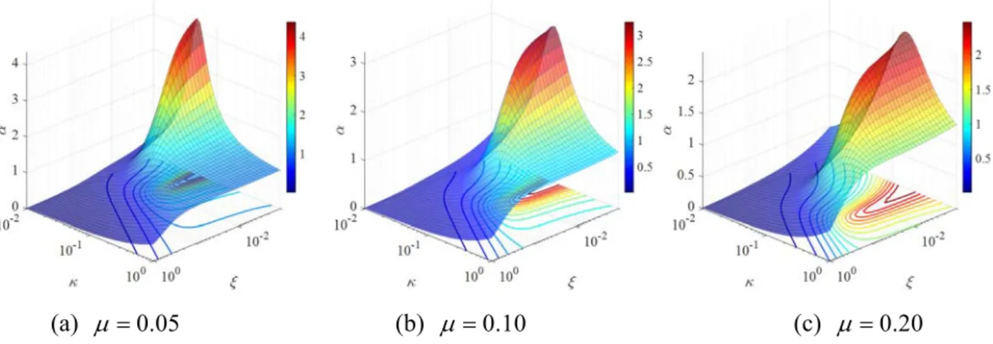
To investigate the impact of these three parameters on and , parametric studies are conducted in this subsection. Supposing that the value of the inertance-mass ratio is constant at
0.05
, 0.10, and 0.20, the values of and are calculated from Eqs. (4)–(5) as the variables and change continuously. Fig. 5 and Fig. 6 show the surface plots of the analysis results, in which is represented by the z-axis. For of an SDOF structure with the TVMD in Fig. 5, the surface plots resemble ditches where the lowest points appear around the upper boundary of the parameter regions of interest. This phenomenon means that the parameter sets with a better damping control effect lie in the bottom of the valleys and a higher damping and larger stiffness could result in a better vibration mitigation effect for the TVMD with a constant inertance-mass ratio. As the inertance-mass ratio increases, the valleys in Fig. 5 (a)–(c) become increasingly shallower, indicating that the response is less sensitive to the change in parameters of the inerter system.
As for the variation pattern of shown in Fig. 6, the peaks of the surfaces (the locations where reaches its maximum value) are located at the lower boundary of . As the inertance-mass ratio, , increases, the peak value of decreases and the location of the surface peak moves along the positive direction of the - axis.
For a practical design, both the vibration mitigation effect and damping enhancement effect are desired. That is, is expected to be as small as possible, whereas is as large as possible. However, Fig. 5 and Fig. 6 show that these two effects cannot occur at the same time, which correspondingly inspires a balance in the trade-off relationship between these two effects. Dealing with this item, a rational design is developed by the closed-form equation in the following section.
Fig. 5. Surface plots of the response mitigation ratio, , of an SDOF structure with the TVMD (SPIS-II) for 0.02,
0.01, 1.0
, and
0.001, 1.0
.(a) 0.05 (b) 0.10 (c) 0.20
Fig. 6. Surface plots of the DDEF of an SDOF structure with the TVMD (SPIS-II) for 0.02,
0.01, 1.0
, and
0.001, 1.0
.2.3. Damping enhancement equation
Inspired by the results in Section 2.2, the theoretical relationship between and can help explain the working mechanism of the inerter system in terms of the vibration control and damping enhancement effect. Regarding this, a fundamental theoretical equation is discovered during the rearrangement of the closed-form stochastic responses derived above. Referring to Eqs. (4)–(5), the closed-form expressions of 2
U
and 2
d
U
are not only related to the design parameters of the TVMD (i.e., , , and ) but also to the amplitude of the input power spectra, S0, and the inherent circular
frequency of the SDOF structure, . In order provide dimensionless indicators to represent the 0 deformation of the primary structure and the EDE, the mean-square responses are made dimensionless by multiplying 3 0 0 2 S : 2 3 3 0 2 2 0 2 0 0 2 2 , d d U U U U S S . (8)
Substituting Eqs. (4)–(5) into Eq. (8), and then multiplying 2
U
and 2
d
U
by and , respectively, the following expressions can be obtained:
2 2 2 2
2 2
2 2
1 2 1 2 2 4 4 , U D D D D (9)
2 2 2 2 2 2 2 2 1 2 2 4 ( 4 ) d U D D , (10)
3 2 2 2 2 2 2 2 2 2 2 2 2 2 1 2 4 4 4 1 , 1 2 2 4 4 . D D (11) Adding 2 U in Eq. (9) to 2 d U in Eq. (10) results in:
2 2 2 2 2 2 2 2 1 2 1 2 2 2 2 2 2 2 2 2 1 1 2 2 2 2 1 2 . 4 4 4 ( 4 ) 1 d U U D D D D D D D D D D (12) That is, 2 2 1 d U U . (13)With the given dimensionless form, i.e., 2
U
and 2
d
U
, and can be written as:
, , ,
U U,0 U ,
, , ,
Ud U . (14) Substituting Eq. (14) into Eq. (13), the following equation can be finally obtained:
2 1 2 1 . (15)
The above equation reveals the essential relationship between the vibration mitigation effect and the damping enhancement effect caused by the inerter system, and thus it is termed as the “damping enhancement equation” in this study. Although the damping enhancement equation is initially derived for the TVMD, it is also true for the TID. A detailed derivation process is provided in Appendix A3.
It can be easily found in the damping enhancement equation that and are negatively correlated if and are kept constant. This logically follows that a more remarkable damping enhancement effect can result in a lower structural response. From Eq. (15), the expression of 2
can be deduced as:
2 2 1 1 . (16)
For a structure with a desired performance (i.e., is prespecified), is inversely 2
proportional to . An overlarge means an excessive deformation would occur for the inner 2
degree of freedom of the inerter system; meanwhile, the forces at the terminals of the inerter system also greatly increase, especially when the damping coefficient is large. Therefore, the suggested implementation of the proposed damping-enhancement-based strategy is to specify an appropriate 2
as well as the vibration mitigation ratio . For the specified and , there is another form of the damping enhancement equation that directly yields the nominal damping ratio , i.e.,
2 2 1 1 . (17) 2.4. Parametric study
The damping enhancement equation can give the value of first. There are then two unknown parameters left, i.e., and , which need to be determined. In this section, a parametric study is
performed to explore the impact of the key parameters on the response mitigation effect and the damping enhancement effect with the purpose of seeking principles for deciding the proper values of
and .
Suppose there are three cases of constant supplemental damping ratio, where 0.001, 0.010,
and 0.100, with the variation trends of and calculated with respect to and using closed-form formulae. Fig. 7 and Fig. 8 show the results in the form of contour plots, where the abscissa
and the ordinate are and in logarithmic scales, respectively. The blue-colored area
representing the minimum value region in Fig. 7 is enclosed by a contour curve, forming a basin shape
in the vicinity of the minimum. As increases, the minimum decreases, which means that the
response can be better suppressed for an inerter system with a higher damping. Meanwhile, the location
of the minimum moves toward the upper right (see Fig. 7) with the augmentation of , which
indicates that higher and values are also required for a better response control effect. For the
contour plots in Fig. 8, the contour lines of seem to be the same as that of , except that the color
maps are inverted. That is, the surface of forms a single-peaked mountain. The negative
correlation between and is what the damping enhancement equation can determine. In the blue
area, the contour line in Fig. 7 and Fig. 8 is a closed loop in which the minimum inerter-mass ratio
can be found at the very left end of the loop. These points where the vertical lines and the contours come in contact with one another at the left side can be considered as a rational parameter set because
these points give the minima of the inerter-mass ratio on the contour line.
(a) 0.001 (b) 0.010 (c) 0.100
Fig. 7. Contour plots of the response mitigation ratio of an SDOF structure with the TVMD
(SPIS-II) for 0.02,
0.01, 1.0
, and
0.01, 1.0
.Fig. 8. Contour plots of the DDEF of an SDOF structure with the TVMD (SPIS-II) for 0.02,
0.01, 1.0
, and
0.01, 1.0
.3. Damping-enhancement-based design strategy and its implementation approach
3.1. Conceptual overview of the damping-enhancement-based design strategy
As mentioned in Section 2.1, with an identical damping coefficient, the inerter system can offer significantly better energy dissipation than a conventional damper if the damping enhancement mechanism is properly designed. Therefore, a novel strategy for determining the parameters of a structure with inerter systems is suggested in this study by explicitly utilizing this benefit of inerter systems. Other than minimizing the structural responses, which is commonly used in existing design methods, the new strategy explicitly considers the damping enhancement effect of an inerter system as a design objective or an index during parameter determination. This is a novel and original design strategy that is different than any other traditional classic theory (e.g., fixed-point theory) and provides a more straightforward method of understanding the mechanism to perform parameter design of an inerter system. Meanwhile, the damping enhancement effect is not pursued unconditionally because the performance of the designed structure should meet the preset requirements.
Several approaches may exist according to the proposed damping-enhancement-based and performance-oriented strategy. Stimulated by the derived damping enhancement equation, the means of guaranteeing the target damping enhancement effect subject to the preset or target vibration mitigation effect is adopted to achieve this strategy.
3.2. Design in the target damping enhancement effect
Combining the damping enhancement effect and performance-oriented design philosophy, both the dynamic responses of the primary structure and inerter system should be of concern when designing the inerter system. Considering that the overpursued maximization of the damping enhancement effect may result in excessive deformation within the inerter system, it will be accompanied by an excessive force for both the inerter system and the primary structure. From this aspect, and under the promise of a satisfactory performance, it is suggested that the degree or extent of the damping enhancement effect be specified before the design process.
In this section, it is suggested that the key parameters of an inerter system be determined based on the specified extents of the vibration mitigation effect and the damping enhancement effect. The extents of these two effects can be quantified by the response mitigation ratio, , and the DDEF , respectively. In other words, the new approach is concerned with controlling both the performance of the primary structure and the inerter system so that the excessive control force can be avoided when the desired performance is achieved. The prespecified target values of and are marked as t and , respectively. t can be decided according to the performance demands [77]. The value of t
t
should be larger than 1 in order to show the advantage of an inerter system, otherwise a single EDE may be more suitable. Given an artificially determined , it should be interactively adjusted t lower if no solution can be found from the following design equation.
The design of an inerter system means determining three key parameters, that is, , , and . As previously stated in the proposed damping enhancement equation, can be directly calculated according to Eq. (17) when and t are specified: t
2 2 1 1 t t . (18)
After obtaining as a constant, the parameter pairs of and that satisfy and t t comprise a certain contour line in Fig. 8. As mentioned in Section 2.4, a set of points on the contours that gives the minima of are chosen as a set of satisfactory parameters. It is cost effective to minimize the added inertance to ensure cost effectiveness. The optimum design problem to find the minimum value of can be written as:
minimize subject to , t . (19)This is an optimization problem with nonlinear constraints, and it can be solved numerically to obtain the undetermined parameters and . As shown in Fig. 8, for a specified contour line there is only one intersection with a vertical line at the points that give a minimum or maximum , whereas there are two intersections for other values of . Finding the minimum for a target DDEF t involves considering as the unknown variable in the equation
,
and ensuring that the t equation has only one solution. In view of the closed-form expressions of , the equation
,
t is a quadratic equation with respect to . Therefore, the discriminant of the equation
,
t should be zero for the quadratic equation to have multiple roots. Taking the TVMD as
an example, the equation
,
can be written out as follows: t
2 2 2 2 2 2 2 2 2 2 2 2 3 2 4 1 2 0 4 4 t t t t t . (20) The discriminant of Eq. (20) can be settled as:
2 2 2 2 2
2 2
2
2
2 2
4 t 1 t 2 4 t t 1 4 4
.(21)
The optimization problem described in Eq. (19) can be transformed into the following set of equations for the TVMD:
2 2 2 2 2 2 2 2 2 2 2 2 2 2 2 2 2 2 2 2 2 2 2 1 4 4 4 2 4 4 4 4 t 1 t 2 4 1 4 4 0 t t t .(22)Similarly, for the TID, the corresponding equations are:
2 2 2 2 2 2 2 2 2 2 2 2 2 2 2 2 2 2 2 2 2 2 2 2 2 2 2 0 4 1 2 4 4 4 4 1 4 2 4 1 4 1 1 4 4 t t t t t t t t . (23)3.3. Design procedure in the target damping enhancement effect
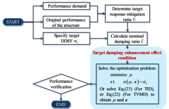
Based on the above equations and discussions, the design procedure of an SDOF structure with an inerter system is summarized in Fig. 9.
Fig. 9. Flowchart of the target-damping-enhancement-based strategy for determining the parameters of an inerter system.
4. Case design and verification
In this section, the target-damping-enhancement-based approach has been applied to determine parameters of the TVMD in an SDOF structure whose period of free vibration is 0.54 s and inherent damping ratio is 0.02 [71]. To achieve different performance levels, the target vibration mitigation
ratio, t, is assumed as 0.60, 0.50, and 0.30 (corresponding to reductions of 40%, 50% and 70% of
the displacement compared to the uncontrolled structure, respectively). Table 2 lists the specified
inherent damping ratio , the target response mitigation ratio t, and the target DDEF t; the
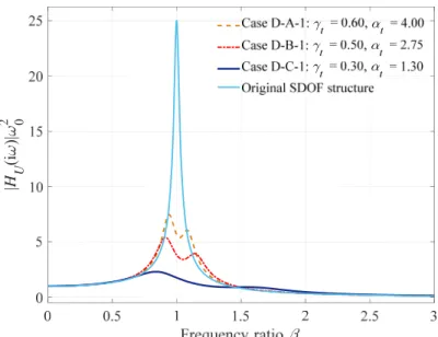
optimal results simultaneously solved according to the design procedure in Fig. 9 are also summarized here. The frequency-domain transfer function from the ground displacement to the displacement of the SDOF structure are also provided in Fig. 10 for design cases D-A-1, D-B-1, and D-C-1. By inspecting the frequency-domain transfer function curves, it can be concluded that the designed TVMDs are
effective for response mitigation. As the preset t decreases, the resonant peaks become
progressively lower, meanwhile the two peaks move away from one another because the fundamental frequency of the supplemental vibrations system increases as the inertance-mass ratio increases.
Fig. 10. Frequency-domain displacement transfer function curves of the SDOF structure with the TVMDs (SPIS-IIs) in Cases D-A-1, D-B-1, and D-C-1.
Comparing the results designed under the condition of different target damping enhancement effects, it can be found that a different expected t value leads to different design results under the same target response mitigation ratio t. Compared to the results obtained following a relative large damping enhancement effect (in the cases of D-A-2, D-B-2, and D-C-2), the nominal damping designed by relatively lower damping enhancement effects is larger, while the corresponding inertance-mass ratio is slightly smaller. The transfer function curves of the structural displacement and the corresponding control force of TVMDs [71] are also provided in Fig. 11 to compare the frequency-domain characteristics of a structure with different parameters under different values. t It can be found in Fig. 11 that the prespecified t may influence the shape of the transfer function curves. Furthermore, for a prespecified lower t a lower control force (i.e., a lower control cost) is needed under the same performance level. That is, the target-damping-enhancement principle is aimed at optimally designing the inerter system with the proper consideration of limiting the control force of the inerter system from being excessive.
(a) Structural displacement (b) Control force of the TVMD (SPIS-II)
|H U (i )| 2 0 0 0.5 1 1.5 2 2.5 3 Frequency ratio 0 5 10 15 20 25 |H U (i )| 2 0 t= 0.60, t= 4.75 t= 0.60, t= 4.00 Original SDOF structure
0 0.5 1 1.5 2 2.5 3 Frequency ratio 0 0.2 0.4 0.6 0.8 1 1.2 |H Fd (i )| t= 0.60, t= 4.75 t= 0.60, t= 4.00
Fig. 11. Frequency-domain transfer function curves of the SDOF structure with TVMDs (SPIS-IIs) in Cases D-A-1 and D-A-2.
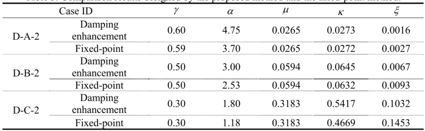
To explain the feature of the proposed design method through a fair comparison with other typical methods, the same inertance-mass ratio is adopted to implement the optimal design using the proposed damping-enhancement-based method and the fixed-point method [47]. Three design cases are studied, with the results summarized in Table 3. On the premise of the same inertance-mass ratio
, the two methods produce almost the same effect of the displacement control. However, in virtue of the explicit utilization of the damping enhancement effect, the TVMD designed by the damping-enhancement-based method exhibits a larger damping enhancement effect by using a lower damping ratio in comparison with the results obtained from the fixed-point method [47]. In other words, the proposed damping enhancement equation yields a more efficient solution to determine the parameters of the inerter system.
By adopting the designed parameters according to the proposed target-damping-enhancement-based approach, a series of time history analyses were conducted for verification. Twenty randomly generated white-noise waves were adopted as the external excitations. After the analysis, the average RMS values of , , and 2
1 2
R were calculated and are listed in Table 4. It can be determined that the expected values, i.e., t and t, match with the average responses of and , which means that the design equation and criteria of this study are reliable. Additionally, the average values of R are very close to 1, which verifies the damping enhancement equation (Eq. (15)).
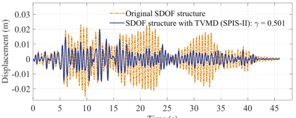
To verify the dynamic performance of a designed structure with a TVMD in the time domain, time history analyses were conducted under a white-noise wave, an artificial seismic wave [78], and the El Centro wave. For the artificial seismic wave, the predominant frequency is equal to that of the SDOF structure. Considering case D-B-1, the deformation responses of both the primary structure and the EDE of the inerter system are shown in Fig. 12 and Fig. 13. The corresponding values for and under each excitation are also indicated in these figures. From the time-history response curves, it can be concluded that the designed inerter system is effective for suppressing the structural response with an amplified deformation in the EDE, i.e., the damping enhancement effect. Meanwhile, for different excitations, the performance level and the damping enhancement extent evaluated by were close to the specified values, i.e., 0.50 and 2.75, respectively. This indicates that the design parameters obtained using white-noise excitation can achieve a good performance against seismic excitations.
(a) Displacement response of an SDOF structure with and without a TVMD (SPIS-II)
0 5 10 15 20 25 30 35 40 45 Time (s) -0.02 -0.01 0 0.01 0.02
0.03 Original SDOF structure
(b) Deformation of the EDE and the displacement of an SDOF structure with a TVMD (SPIS-II) Fig. 12. Time history responses of an SDOF structure with a TVMD (SPIS-II) under an artificial
seismic wave (Case: D-B-1, t 0.50, t 2.75).
(a) Displacement response of an SDOF structure with and without a TVMD (SPIS-II)
(b) Deformation of the EDE and the displacement of an SDOF structure with a TVMD (SPIS-II) Fig. 13. Time history responses of an SDOF structure with a TVMD (SPIS-II) under the El Centro
wave (Case: D-B-1, t 0.50, t 2.75).
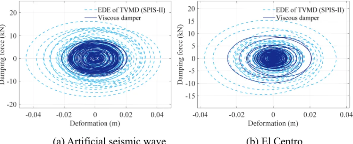
For the sake of illustrating the damping enhancement effect more clearly, a conventional viscous damper, whose damping coefficient is equal to that of the EDE of the TVMD, was equipped with the SDOF structure. The hysteretic curves of the sole viscous dampers and the EDE of the TVMD are depicted in Fig. 14. It can be observed that the maximum damping force and deformation are both enlarged in the EDE of the TVMD, benefiting from the damping enhancement mechanism. The normalized energy response curves of an SDOF structure with a TVMD and a viscous damper are shown in Fig. 15 under the excitation of the El Centro wave as an example. The curves show that the
0 5 10 15 20 25 30 35 40 45 Time (s) -0.04 -0.02 0 0.02 0.04 0.06
Deformation of EDE of TVMD (SPIS-II): = 2.756 Deformation of TVMD (SPIS-II) 0 10 20 30 40 50 Time (s) -0.02 0 0.02 0.04
Original SDOF structure
SDOF structure with TVMD (SPIS-II): = 0.495
0 10 20 30 40 50 Time (s) -0.04 -0.02 0 0.02
0.04 Deformation of EDE of TVMD (SPIS-II): = 2.757 Deformation of TVMD (SPIS-II)
percentage of energy dissipated by additional damping devices can be increased from approximately 25% to 75% if the viscous damper is replaced with a TVMD with the same damping coefficient. The increased vibration energy dissipation proportion of the TVMD means that less energy is transferred into the primary structure. This is also one of the reasons for using a damping-enhancement-based strategy for determining the parameters of the inerter systems.
(a) Artificial seismic wave (b) El Centro
Fig. 14. Hysteretic curves of the EDE of the TVMD (SPIS-II) and a viscous damper subject to different excitations.
(a) SDOF with TVMD (SPIS-II) (b) SDOF with viscous damper
Fig. 15. Normalized energy response curves of an SDOF structure with TVMD (SPIS-II) under the El Centro wave.
5. Conclusions
The damping enhancement equation, which is a simple-form quantificational description of the relationship between the response mitigation effect and the damping enhancement effect for a structure equipped with an inerter system, was discovered and proven in this study. Combined with demand-oriented design philosophy, the damping enhancement equation yielded the target-damping-enhancement-based design principles. The main conclusions of this study can be summarized as follows.
(1) The damping enhancement equation concisely reveals the essential relationship between the
Dam pi ng f orce (k N) Dam pi ng f orce (k N) 0 10 20 30 40 50 Time (s) 0 0.2 0.4 0.6 0.8 1 No rm alized ene rgy
Energy dissipated by TVMD (SPIS-II) Energy dissipated by inherent damping Kinetic and potential energy
0 10 20 30 40 50 Time (s) 0 0.2 0.4 0.6 0.8 1 No rm alized ene rgy
Energy dissipated by visvous damper Energy dissipated by inherent damping Kinetic and potential energy
damping enhancement effect and the vibration mitigation effect of inerter systems. The damping enhancement equation can explain the working mechanism of an inerter systems from an explicit perspective and simplify the parameter determination of an inerter system in a direct manner.
(2) The proposed design strategy presents an explicit damping enhancement mechanism of inerter systems, so a high-energy dissipation efficiency can be obtained for structural vibration mitigation. Under a specified performance level, pursuing the target damping enhancement effect is a feasible approach for realizing the damping-enhancement-based design strategy for inerter systems. A solution of the equivalent optimization problem can provide a parameter set that satisfies the performance demand with the preferred target damping enhancement effect.
(3) The proposed target-damping-enhancement-based design approach is an implementation of the damping-enhancement-based strategy. Specified indicators, i.e., the target response mitigation ratio and the target damping deformation enhancement factor, guarantee satisfaction of the performance demand with the proper damping enhancement effect and control force of the inerter system, which can produce cost-effective design schemes.
(4) The derived closed-form damping enhancement equation yields a direct and analytical way of designing the damping parameter of an inerter system. Given the designed damping parameter, determining the inertance and stiffness is equivalent to an optimization problem that minimizes the inertance-mass ratio.
(5) The research object of this study is an SDOF structure equipped with two representative types of inerter systems. However, the damping-enhancement-based design strategy is not confined to this. The application of this strategy in other inerter systems and multi-degree-of-freedom (MDOF) structures with inerter systems are definitely required to develop the damping-enhancement-based theory.
Acknowledgments
This study was supported by the National Natural Science Foundation of China (Grant No. 51978525), the Natural Science Foundation of Shandong Province (No. ZR2018BEE033), and the Japan Society for the Promotion of Science (JSPS) under Grant-in-Aid for Scientific Research (B) (No. 1801577).
Appendix
A1. Derivation of the closed-form expressions of the mean square response for SDOF structures with inerter systems
Here the TVMD is used as an example to demonstrate the derivation process of the stochastic responses of a TVMD-equipped structure, including the displacement response of the primary structure and the deformation of the EDE. As shown in Fig. 4, the governing equation of an SDOF structure with a TVMD is:
2 2 0 0 0 2 0 0 2 2 d g d d d u u u u u u u u u u . (A1)Assuming that the input excitation is a harmonic motion with a circular frequency of , Eq. (A1) can be transformed into the Laplace domain:
2 2 0 0 2 2 0 2 0 0 2 ( ) 2 d g d d d s s U s sU U U U U s s s s s s s s U s U U U s , (A2)where si and i is the imaginary unit. U s
, Ug
s , and Ud
s are the Laplace
and d
U s U s can be easily solved. Accordingly, the frequency-domain transfer functions
i UH and HU d,
i are expressed as:
2 2 0 0 2 4 2 2 2 2 0 0 0 0 0 2 0 2 4 2 2 2 2 0 0 0 0 , 0 2 2 2 1 2 2 1 ) ( ) ( ) ( ) ( U g d U d g U s H s U s U s H s s s s s s s U s s s s s . (A3)On the hypothesis that the input excitation is white noise with the amplitude of the power spectrum density, S0, then the mean-square of the displacement response, U2 , and the deformation of the EDE, 2
d
U
, can be expressed as follows:
0 2 i i U S HU HU d
, (A4)
, , 0 2 i i d U S HU d HU d d
. (A5)The integral in Eq. (A5) can be converted into closed-form rational functions, as described in [79].
A2. Closed-form expressions of responses for SDOF structures with inerter systems
To provide dimensionless evaluation indicators for the structural displacement and EDE deformation, the dimensionless mean-squares 2
U
and 2
d
U
are defined as:
0 2 03 2 2 03 2 0 , 2 2 d d U U U U S S . (A6) The expressions of 2 U and 2 d U
of the basic inerter systems are listed in Table A1. Table A2 lists the closed-form expressions of the deformation of the EDE 2
,
U d
of classic series-parallel layout inerter systems.
A3. Derivation details of the damping enhancement equation for inerter systems
With the help of the expressions of 2
U and 2 , U d in Appendix A1, 2 U and 2 d U of the TID and TVMD can be obtained and are listed in Table A4.
By adding 2
U
and 2
d
U
in Table A1, we can obtain the damping enhancement formula as:
1 1
2 2
1 2 1 2 1 2 1 2 1 2 2 2 d U U D N D N N N D D D D D D D D . (A7)Properly explaining the expressions, it can be stated that they are logical. From Eq. (12), the meaningful damping enhancement formula can be expressed as:
2 2 1
d
U U
. (A8)
References
1. Yao JTP. Concept of structural control. Journal of the Structural Division 1972; 98(ST7): 1567-1574.
2. Housner GW, Bergman LA, Caughey TK, Chassiakos AG, Claus RO, Masri SF, Skelton RE, Soong TT, Spencer BF, Yao JTP. Structural control: Past, present, and future. Journal of
http://dx.doi.org/10.1061/(Asce)0733-9399(1997)123:9(897).
3. Takewaki I, Fujita K, Yamamoto K, Takabatake H. Smart passive damper control for greater building earthquake resilience in sustainable cities. Sustainable Cities and Society 2011; 1(1): 3-15. DOI: https://doi.org/10.1016/j.scs.2010.08.002.
4. Kalehsar HE, Khodaie N. Wind-induced vibration control of super-tall buildings using a new combined structural system. Journal of Wind Engineering and Industrial Aerodynamics 2018; 172: 256-266. DOI: https://doi.org/10.1016/j.jweia.2017.10.029.
5. Chen QJ, Zhao ZP, Xia YY, Pan C, Luo H, Zhang RF. Comfort based floor design employing tuned inerter mass system. Journal of Sound and Vibration 2019; 458: 143-157. DOI: https://doi.org/10.1016/j.jsv.2019.06.019.
6. Dai J, Xu ZD, Gai PP. Tuned mass-damper-inerter control of wind-induced vibration of flexible structures based on inerter location. Engineering Structures 2019; 199: 109585. DOI: https://doi.org/10.1016/j.engstruct.2019.109585.
7. Giaralis A, Petrini F. Wind-induced vibration mitigation in tall buildings using the Tuned Mass-Damper-Inerter. Journal of Structural Engineering 2017; 143(9). DOI:
https://doi.org/10.1061/(asce)st.1943-541x.0001863.
8. Smith MC, Wang FC. Performance benefits in passive vehicle suspensions employing inerters.
Vehicle System Dynamics 2004; 42(4): 235-257. DOI:
http://dx.doi.org/10.1080/00423110412331289871.
9. Scheibe F, Smith MC. Analytical solutions for optimal ride comfort and tyre grip for passive vehicle suspensions. Vehicle System Dynamics 2009; 47(10): 1229-1252. DOI: https://doi.org/10.1080/00423110802588323.
10. Hu Y, Chen MZQ, Sun Y. Comfort-oriented vehicle suspension design with skyhook inerter configuration. Journal of Sound and Vibration 2017; 405: 34-47. DOI:
https://doi.org/10.1016/j.jsv.2017.05.036.
11. Shen Y, Liu Y, Chen L, Yang X. Optimal design and experimental research of vehicle suspension based on a hydraulic electric inerter. Mechatronics 2019; 61: 12-19. DOI: https://doi.org/10.1016/j.mechatronics.2019.05.002.
12. Ning D, Sun S, Du H, Li W, Zhang N, Zheng M, Luo L. An electromagnetic variable inertance device for seat suspension vibration control. Mechanical Systems and Signal Processing 2019; 133: 106259. DOI: https://doi.org/10.1016/j.ymssp.2019.106259.
13. Jiang JZ, Matamoros-Sanchez AZ, Goodall RM, Smith MC. Passive suspensions incorporating inerters for railway vehicles. Vehicle System Dynamics 2012; 50(sup1): 263-276. DOI: https://doi.org/10.1080/00423114.2012.665166.
14. Wang FC, Hsieh MR, Chen HJ. Stability and performance analysis of a full-train system with inerters. Vehicle System Dynamics 2012; 50(4): 545-571. DOI:
https://doi.org/10.1080/00423114.2011.606368.
15. Hwang JS, Kim J, Kim YM. Rotational inertia dampers with toggle bracing for vibration control of a building structure. Engineering Structures 2007; 29(6): 1201-1208. DOI: https://dx.doi.org/10.1016/j.engstruct.2006.08.005.
16. Masri SF, Caffrey JP. Transient Response of a SDOF System With an Inerter to Nonstationary Stochastic Excitation. Journal of Applied Mechanics 2017; 84(4). DOI:
https://doi.org/10.1115/1.4035930.
17. Asai T, Watanabe Y. Outrigger tuned inertial mass electromagnetic transducers for high-rise buildings subject to long period earthquakes. Engineering Structures 2017; 153: 404-410. DOI: https://doi.org/10.1016/j.engstruct.2017.10.040.
18. Taflanidis AA, Giaralis A, Patsialis D. Multi-objective optimal design of inerter-based vibration absorbers for earthquake protection of multi-storey building structures. Journal of the Franklin
Institute 2019; 356(14): 7754-7784. DOI: https://doi.org/10.1016/j.jfranklin.2019.02.022.
Earthquakes. Journal of Structural Engineering 2019; 145(2). DOI:
https://doi.org/10.1061/(asce)st.1943-541x.0002267.
20. Krenk S. Resonant inerter based vibration absorbers on flexible structures. Journal of the Franklin
Institute 2019; 356(14): 7704-7730. DOI: https://doi.org/10.1016/j.jfranklin.2018.11.038.
21. Basili M, De Angelis M, Pietrosanti D. Modal analysis and dynamic response of two adjacent single-degree-of-freedom systems linked by spring-dashpot-inerter elements. Engineering
Structures 2018; 174: 736-752. DOI: https://doi.org/10.1016/j.engstruct.2018.07.048.
22. Wang X, He T, Shen Y, Shan Y, Liu X. Parameters optimization and performance evaluation for the novel inerter-based dynamic vibration absorbers with negative stiffness. Journal of Sound and
Vibration 2019; 463: 114941. DOI: https://doi.org/10.1016/j.jsv.2019.114941.
23. Giaralis A, Taflanidis AA. Optimal tuned mass-damper-inerter (TMDI) design for seismically excited MDOF structures with model uncertainties based on reliability criteria. Structural Control
& Health Monitoring 2018; 25(2). DOI: https://doi.org/10.1002/stc.2082.
24. Shen W, Niyitangamahoro A, Feng Z, Zhu H. Tuned inerter dampers for civil structures subjected to earthquake ground motions: optimum design and seismic performance. Engineering Structures 2019; 198: 109470. DOI: https://doi.org/10.1016/j.engstruct.2019.109470.
25. Cao L, Li C. Tuned tandem mass dampers-inerters with broadband high effectiveness for structures under white noise base excitations. Structural Control and Health Monitoring 2019; 26(4): e2319. DOI: https://doi.org/10.1002/stc.2319.
26. Luo H, Zhang RF, Weng DG. Mitigation of liquid sloshing in storage tanks by using a hybrid control method. Soil Dynamics and Earthquake Engineering 2016; 90: 183-195. DOI: http://dx.doi.org/10.1016/j.soildyn.2016.08.037.
27. Zhang RF, Zhao ZP, Pan C. Influence of mechanical layout of inerter systems on seismic mitigation of storage tanks. Soil Dynamics and Earthquake Engineering 2018; 114: 639–649. DOI: https://doi.org/10.1016/j.soildyn.2018.07.036.
28. Jiang YY, Zhao ZP, Zhang RF, De Domenico D, Pan C. Optimal design based on analytical solution for storage tank with inerter isolation system. Soil Dynamics and Earthquake
Engineering 2020; 129: 105924. DOI: https://doi.org/10.1016/j.soildyn.2019.105924.
29. Hu Y, Wang J, Chen MZQ, Li Z, Sun Y. Load mitigation for a barge-type floating offshore wind turbine via inerter-based passive structural control. Engineering Structures 2018; 177: 198-209. DOI: https://doi.org/10.1016/j.engstruct.2018.09.063.
30. Zhang RF, Zhao ZP, Dai KS. Seismic response mitigation of a wind turbine tower using a tuned parallel inerter mass system. Engineering Structures 2019; 180: 29-39. DOI: https://doi.org/10.1016/j.engstruct.2018.11.020.
31. Ma R, Bi K, Hao H. Mitigation of heave response of semi-submersible platform (SSP) using tuned heave plate inerter (THPI). Engineering Structures 2018; 177: 357-373. DOI: https://doi.org/10.1016/j.engstruct.2018.09.085.
32. Lazar IF, Neild SA, Wagg DJ. Vibration suppression of cables using tuned inerter dampers.
Engineering Structures 2016; 122: 62-71. DOI: https://doi.org/10.1016/j.engstruct.2016.04.017.
33. Li Y, Shen W, Zhu H. Vibration mitigation of stay cables using electromagnetic inertial mass dampers: Full-scale experiment and analysis. Engineering Structures 2019; 200: 109693. DOI: https://doi.org/10.1016/j.engstruct.2019.109693.
34. Luo JN, Jiang JZ, Macdonald JHG. Cable Vibration Suppression with Inerter-Based Absorbers.
Journal of Engineering Mechanics 2019; 145(2): 15. DOI:
https://doi.org/10.1061/(asce)em.1943-7889.0001554.
35. Shi X, Zhu S. Dynamic characteristics of stay cables with inerter dampers. Journal of Sound and
Vibration 2018; 423: 287-305. DOI: https://doi.org/10.1016/j.jsv.2018.02.042.
36. Zhang SY, Jiang JZ, Neild S. Optimal configurations for a linear vibration suppression device in a multi-storey building. Structural Control & Health Monitoring 2017; 24(3). DOI: https://doi.org/10.1002/stc.1887.
37. Moraes FdH, Silveira M, Gonçalves PJP. On the dynamics of a vibration isolator with geometrically nonlinear inerter. Nonlinear Dynamics 2018; 93(3): 1325-1340. DOI: https://doi.org/10.1007/s11071-018-4262-6.
38. De Domenico D, Ricciardi G. Improving the dynamic performance of base-isolated structures via tuned mass damper and inerter devices: A comparative study. Structural Control & Health
Monitoring 2018; 25(10). DOI: https://doi.org/10.1002/stc.2234.
39. Zhao ZP, Chen QJ, Zhang RF, Pan C, Jiang YY. Optimal design of an inerter isolation system considering the soil condition. Engineering Structures 2019; 196: 109324. DOI: https://doi.org/10.1016/j.engstruct.2019.109324.
40. Wang Y, Meng H, Zhang B, Wang R. Analytical research on the dynamic performance of semi-active inerter-based vibration isolator with acceleration–velocity-based control strategy.
Structural Control & Health Monitoring 2019; 26(4): e2336. DOI:
https://doi.org/10.1002/stc.2336.
41. Ye K, Shu S, Hu L, Zhu H. Analytical solution of seismic response of base-isolated structure with supplemental inerter. Earthquake Engineering & Structural Dynamics 2019; 48(9): 1083-1090. DOI: https://doi.org/10.1002/eqe.3165.
42. Li L, Liang Q. Effect of inerter for seismic mitigation comparing with base isolation. Structural
Control & Health Monitoring 2019; 26(10): e2409. DOI: https://doi.org/10.1002/stc.2409.
43. Zhao ZP, Zhang RF, Jiang YY, Pan C. Seismic response mitigation of structures with a friction pendulum inerter system. Engineering Structures 2019; 193: 110-120. DOI: https://doi.org/10.1016/j.engstruct.2019.05.024.
44. Sun H, Zuo L, Wang X, Peng J, Wang W. Exact H2 optimal solutions to inerter-based isolation systems for building structures. Structural Control and Health Monitoring 2019; 26(6): e2357. DOI: https://doi.org/10.1002/stc.2357.
45. Čakmak D, Tomičević Z, Wolf H, Božić Ž, Semenski D, Trapić I. Vibration fatigue study of the helical spring in the base-excited inerter-based isolation system. Engineering Failure Analysis 2019; 103: 44-56. DOI: https://doi.org/10.1016/j.engfailanal.2019.04.064.
46. Smith MC. Synthesis of mechanical networks: the inerter. IEEE Transactions on Automatic
Control 2002; 47(10): 1648-1662. DOI: https://dx.doi.org/10.1109/TAC.2002.803532.
47. Ikago K, Saito K, Inoue N. Seismic control of single-degree-of-freedom structure using tuned viscous mass damper. Earthquake Engineering & Structural Dynamics 2012; 41(3): 453-474. DOI: https://dx.doi.org/10.1002/eqe.1138.
48. Takewaki I, Murakami S, Yoshitomi S, Tsuji M. Fundamental mechanism of earthquake response reduction in building structures with inertial dampers. Structural Control & Health Monitoring 2012; 19(6): 590-608. DOI: https://doi.org/10.1002/stc.457.
49. Gonzalez-Buelga A, Lazar IF, Jiang JZ, Neild SA, Inman DJ. Assessing the effect of nonlinearities on the performance of a tuned inerter damper. Structural Control & Health
Monitoring 2017; 24(3). DOI: https://doi.org/10.1002/stc.1879.
50. Barredo E, Blanco A, Colin J, Penagos VM, Abundez A, Gerardo Vela L, Meza V, Cruz RH, Mayen J. Closed-form solutions for the optimal design of inerter-based dynamic vibration absorbers. International Journal of Mechanical Sciences 2018; 144: 41-53. DOI: https://doi.org/10.1016/j.ijmecsci.2018.05.025.
51. Kawamata S. Development of a vibration control system of structures by means of mass pumps. 1973, Institute of Industrial Science, University of Tokyo: Tokyo, Japan.
52. Arakaki T, Kuroda H, Arima F, Inoue Y, Baba K. Development of seismic devices applied to ball screw : Part 1 Basic performance test of RD-series. AIJ Journal of Technology and Design 1999; 5(8): 239-244. DOI: https://doi.org/10.3130/aijt.5.239_1.
53. Arakaki T, Kuroda H, Arima F, Inoue Y, Baba K. Development of seismic devices applied to ball screw : Part 2 Performance test and evaluation of RD-series. AIJ Journal of Technology and
54. Saito K, Sugimura Y, Inoue N. A study on response control of a structure using viscous damper with inertial mass. Journal of structural engineering 2008; B54: 635-648.
55. Arai T, Aburakawa T, Ikago K, Hori N, Inoue N. Verification on effectiveness of a tuned viscous mass damper and its applicability to non-linear structural systems. Journal of Structural &
Construction Engineering 2009; 74(645): 1993-2002. DOI: https://doi.org/10.3130/aijs.74.1993.
56. Brzeski P, Lazarek M, Perlikowski P. Experimental study of the novel tuned mass damper with inerter which enables changes of inertance. Journal of Sound and Vibration 2017; 404: 47-57. DOI: https://doi.org/10.1016/j.jsv.2017.05.034.
57. Zhao ZP, Zhang RF, Jiang YY, Pan C. A tuned liquid inerter system for vibration control.
International Journal of Mechanical Sciences 2019; 164: 105171. DOI:
https://doi.org/10.1016/j.ijmecsci.2019.105171.
58. Faraj R, Jankowski L, Graczykowski C, Holnicki-Szulc J. Can the inerter be a successful shock-absorber? The case of a ball-screw inerter with a variable thread lead. Journal of the Franklin
Institute 2019; 356(14): 7855-7872. DOI: https://doi.org/10.1016/j.jfranklin.2019.04.012.
59. Palacios-Quiñonero F, Rubió-Massegú J, Rossell JM, Karimi HR. Design of inerter-based multi-actuator systems for vibration control of adjacent structures. Journal of the Franklin Institute 2019; 356(14): 7785-7809. DOI: https://doi.org/10.1016/j.jfranklin.2019.03.010.
60. John EDA, Wagg DJ. Design and testing of a frictionless mechanical inerter device using living-hinges. Journal of the Franklin Institute 2019; 356(14): 7650-7668. DOI: https://doi.org/10.1016/j.jfranklin.2019.01.036.
61. Lazarek M, Brzeski P, Perlikowski P. Design and modeling of the CVT for adjustable inerter.
Journal of the Franklin Institute 2019; 356(14): 7611-7625. DOI:
https://doi.org/10.1016/j.jfranklin.2018.11.011.
62. Kras A, Gardonio P. Active vibration control unit with a flywheel inertial actuator. Journal of
Sound and Vibration 2020; 464: 114987. DOI: https://doi.org/10.1016/j.jsv.2019.114987.
63. Javidialesaadi A, Wierschem NE. An inerter-enhanced nonlinear energy sink. Mechanical
Systems and Signal Processing 2019; 129: 449-454. DOI:
https://doi.org/10.1016/j.ymssp.2019.04.047.
64. Málaga-Chuquitaype C, Menendez-Vicente C, Thiers-Moggia R. Experimental and numerical assessment of the seismic response of steel structures with clutched inerters. Soil Dynamics and
Earthquake Engineering 2019; 121: 200-211. DOI: https://doi.org/10.1016/j.soildyn.2019.03.016.
65. Zhao ZP, Zhang RF, Lu Z. A particle inerter system for structural seismic response mitigation.
Journal of the Franklin Institute 2019; 356(14): 7669-7688. DOI:
https://doi.org/10.1016/j.jfranklin.2019.02.001.
66. Den Hartog JP. Mechanical vibrations. 4 ed. 1956, Dover: New York: McGraw-Hill.
67. Hu Y, Chen MZQ, Shu Z, Huang L. Analysis and optimisation for inerter-based isolators via fixed-point theory and algebraic solution. Journal of Sound and Vibration 2015; 346: 17-36. DOI: https://doi.org/10.1016/j.jsv.2015.02.041.
68. Chen QJ, Zhao ZP, Zhang RF, Pan C. Impact of soil–structure interaction on structures with inerter system. Journal of Sound and Vibration 2018; 433: 1-15. DOI: https://doi.org/10.1016/j.jsv.2018.07.008.
69. Pan C, Zhang RF, Luo H, Li C, Shen H. Demand-based optimal design of oscillator with parallel-layout viscous inerter damper. Structural Control & Health Monitoring 2018; 25(1): e2051. DOI: https://doi.org/10.1002/stc.2051.
70. Lazar IF, Neild SA, Wagg DJ. Using an inerter-based device for structural vibration suppression.
Earthquake Engineering & Structural Dynamics 2014; 43(8): 1129-1147. DOI:
https://doi.org/10.1002/eqe.2390.
71. Pan C, Zhang RF. Design of structure with inerter system based on stochastic response mitigation ratio. Structural Control & Health Monitoring 2018; 25(6): e2169. DOI: https://doi.org/10.1002/stc.2169.
![Fig. 1. Schematic representation of the damping enhancement effect of an inerter system [47]](https://thumb-ap.123doks.com/thumbv2/123deta/5926472.1051732/4.892.201.682.839.1045/fig-schematic-representation-damping-enhancement-effect-inerter.webp)
![Fig. 2. Mechanical models of classic series-parallel layout inerter systems [71].](https://thumb-ap.123doks.com/thumbv2/123deta/5926472.1051732/5.892.171.723.300.610/mechanical-models-classic-series-parallel-layout-inerter-systems.webp)

![Table A1. Closed-form expressions of the mean square displacement response of an SDOF structure with an inerter system U2 [71]](https://thumb-ap.123doks.com/thumbv2/123deta/5926472.1051732/26.892.77.815.112.220/table-closed-expressions-square-displacement-response-structure-inerter.webp)
