CELSS学 会 誌 VOL.13 NO.2 (2001年3月)
Characteristics
of the photocatalytic
reactor
with an annular
array
of glass
tubes
surrounding
a light source:
2. Kinetic analysis
Satoru Fukinbara and Fumihide Shiraishi
Department of Biochemical Engineering and Science . Faculty of Computer Scien and Systems Engineering, Kyushu Institute of Technology, 680-4 Kawazu, Iizuka 820, Japan
ABSTRACT
In a series of two papers, the performance of a photocatalytic reactor, where a light source is surrounded by an annular array of 19 transparent glass tubes, giving a zigzag-flow path as a whole , has been studied both experimentally and theoretically. In this second paper, the photocatalytic reactor , constituted by a 6-W blacklight fluorescent lamp and Pyrex glass tubes, has been used to carry out the photocatalytic decomposition of DNP . The intrinsic kinetic constant was determined from the initial reaction rate that were measured at high initial reactant concentrations and the intrinsic adsorption equilibrium constant and mass-transfer coefficient were determined by the methods previously established in an immobilized-enzyme system. The result calculated by applying these parameter values to each mathematical model, taking into consideration the effect of film-diffusional resistance, for the photocatalytic reactor system operating in a batch, batch-recirculation, or continuous-flow mode was in good agreement with the experimental values, which indicates the validity of the mathematical models. At an initial DNP concentration of 11.6 g m3, the effectiveness factor was 0.92, showing that the effect of film-diffusional resistance is not so high in the present system. Although the experiment was carried out in the batch-recirculation reactor system, the result of theoretical analysis indicated that the present reaction condition can be approximately regarded as the batch reaction condition. The method previously proposed in an immobilized-enzyme system were found to be useful to determine the intrinsic kinetic parameters and mass-transfer coefficient in the present photocatalytic reactor system.
Key words: photocatalytic reactor, kinetic analysis, intrinsic kinetic parameter, mass-transfer coefficient , titanium dioxide, 2,4-dinitrophenol
*
To whom correspondence should be addressed. Telephone: (Japan)-948-29-7827
Fax: (Japan)-948-29-7801
(2001年1月24日 受 付,2001年4月4日 受 理) 1 INTRODUCTION
Titanium oxide excited by UV light can decompose many kinds of organic compounds1-16). To treat wastewater or purify the air, various kinds of materials have been coated with titanium oxide and their performances have been investigated for the use as a photocatalytic reactor10,12,13,17-22).
To carry out kinetic analysis of such photocatalytic reactors, the experimental data may be taken in a continuous-flow operation mode23-25); in this case, the reaction mixture is allowed to flow slowly through the reactor such that the conversion reaches a certain magnitude at the reactor exit. When the reactant concentration is equal to or less than a ppb level,
however, the film-mass transfer resistance would unexpectedly be so significant that the kinetic parameters determined from measured values by a general method are not the intrinsic values but the apparent values that include the effect of mass-transfer resistance, or diffusional resistance26,27). Since these values can not be used in the reactor design, it is necessary to introduce an alternative method that makes it possible to certainly determine the intrinsic kinetic parameters.
In general, the rate of the photocatalytic reaction is described by a Langmuir-Hinshelwood (L-H) type28). In an enzymatic reaction, on the other hand, a similar type called Michaelis-Menten type is used29), the functional relationship of which expression is fundamentally the same as that of the L-H expression. Shiraishi30) previously derived general expressions for the apparent maximum reaction rate and Michaelis constant in an immobilized enzyme reaction. Because of exact description of the influences of various environmental factors associated with immobilized enzyme reactions on the kinetic parameters, these expressions were utilized to construct a method for determination of the intrinsic kinetic parameters from the apparent kinetic parameters that are easily obtained from the experimental data31,32). The intrinsic kinetic parameters thus determined were further used to express the mass-transfer coefficient in the packed-bed immobilized enzyme reactor as a function of the liquid flow rate33). The calculated results by use of these parameter values were in good agreement with the experimental results 33,34). This series of procedures are also applicable to the
photocatalytic reactor system.
Using a mathematical model for the photocatalytic reactor, one may undertake to elucidate the reactor performance. It is easy to predict that the photocatalytic reactor system would routinely be affected by the diffusional resistance. In this system, however, few papers have been published on the kinetic analysis of photocatalytic reaction data under taking into consideration the effect of diffusional resistance on the reactor performance.
In a previous paper35), the authors constructed a mathematical model for the batch-recirculation reactor system that describes the treatment of a certain substance in a closed room and proposed a highly-reliable method to numerically solve relevant differential equations. Furthermore, the performance of such a reactor system was elucidated based on the result of numerical calculation. It is now necessary to indicate the validity of the mathematical model by using experimental data in an actual closed system.
The purpose of the present work is to elucidate the performance of a photocatalytic reactor where a light source is surrounded by an annular array of 19 transparent glass tubes (5 mm in inside diameter), whose inner surface is coated with a thin film of titanium oxide, connected so as to give a zigzag-flow path as a whole. The results will be discussed in two papers. In the first paper36), the effects of different light sources and glass tube materials on the reactor activity were investigated. As a result, it was concluded that a combination of Pyrex glass tubes as a support with a blacklight fluorescent lamp as a light source is reasonable in the present photocatalytic reactor .
In this second paper, the procedure of kinetic analysis established in the immobilized enzyme system is applied to the experimental data for the decomposition of 2 ,4-dinitrophenol in the photocatalytic reactor consisting of Pyrex glass tubes and a blacklight fluorescent lamp . That is, the intrinsic kinetic parameters , the kinetic constant k and the adsorption equilibrium constant KH, are determined from batch-recirculation reaction data and the mass-transfer coefficient is then expressed in terms of the liquid flow rate using continuous -flow reaction data. These values are also used to elucidate the performance of the photocatalytic reactor .
CELSS学 会 誌 VOL.13 NO.2 (2001年3月)
2 THEORETICAL 2.1 Rate of photocatalytic reaction
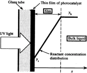
Consider a system where an aqueous solution containing a reactant flows in a glass tube whose inner surface is coated with a transparent thin film of titanium oxide, i.e. photocatalyst (Fig 1) and
UV-Figure 1. Schematic of a reactant concentration profile in vicinity of photocatalyst coated on a glass tube. irradiation is carried out from the outside of the glass tube. The reactant first diffuses through a liquid film formed in the vicinity of the thin film of titanium oxide from the bulk liquid and then decomposes on the surface of the UV-excited photocatalyst. The photocatalytic reaction proceeds according to the L-H type mechanism. Assuming that the system is at a steady state and the diffusion rate of the reactant from the bulk liquid to the surface of the photocatalyst is equal to the rate of photocatalytic reaction at a given position on the glass surface, one gets
(1) Solving Eq.(1) for y(r)ps provides
(2) In the present system, the effectiveness factor is given by37)
(3)
Substituting Eq.(2) into Eq.(3) and then arranging using the dimensionless reactant concentration in the bulk liquid:
βb=y(r)pKH (4)
and the modulus expressing the magnitude of the diffusional resistance: φ=kKH/kL (5) one obtains (6) where ρ=βb+φ+1 (7) and ξ=ρ2-4βbφ (8)
The value of E1 lies between zero and unity. When E1 is much smaller than unity, the diffusional resistance becomes larger, i.e. the system is diffusion-limited. In the absence of film-diffusional resistance, E1 is equal to unity. Likewise, when the value of ƒÓ is equal to unity, there is no diffusional effect. the larager the value of ƒÓ, the larger the diffusional resistance. Introduction of the effectiveness factor provides the expression of the rate of photocatalytic reaction in terms of the reactant concentration in the bulk liquid, y(r)p, as
(9) 2.2 Mathematical model for a batch-recirculation
reactor system
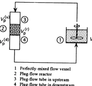
As shown in Fig 2, the reactor system in the present work consists of a perfectly-mixed flow vessel with a volume of Vs, plug-flow photocatalytic reactor with a volume of Vp(r), and upstream and downstream plug-flow tubes with a volume of V
p(u) and Vp(d), respectively, located before and after of the reactor (corresponding to connecting tubes)35). The reactant mixture is well-mixed and distributed uniformly in the vessel. At t<0 , the whole system is filled with an aqueous solution of the reactant and at t=0, the UV light is switched-on so that the photocatalytic reaction starts. Since the circulation flow rate is so large, the conversion per one pass of the reactant mixture through the photocatalytic reactor is very small.
Mass balance for the reactant concentration in the perfectly-mixed flow vessel yields
Figure 2. Schematic of a batch-recirculation photocatalytic reactor system.
(10) Expressing the reactant concentration at the reactor exit y(r)p(f)|out, the reactant concentration at the entrance of the perfectly-mixed flow vessel is given by
(11) On the other hand, the mass-balance equation for the plug-flow reactor is written as
(12) with
(13) and
(14) For the upstream plug-flow tube located before the plug-flow reactor, the reactant concentrations are given by
(15) at the entrance and
(16) at the exit. Likewise, for the downstream plug-flow tube located after the plug-flow reactor , the reactant
concentrations are given by
(17) at the entrance and
(18) at the exit. For the whole system , the initial condition is given by
(19) The differential equation for the plug-flow reactor can be numerically integrated by Runge-Kutta method38), whereas this method is not directly applicable to the differential equation for the perfectly-mixed flow vessel because the solution at the reactor entrance is given only at t=ih (i=0, 1, 2, ...) but not at t=ih+h/2 (i=0, 1, 2, ....). For this reason, a modified Runge-Kutta method , as described in a previous paper35), was applied . The same stepsize was used over the plug-flow region , which made the numerical calculation highly stable . The accuracy of the numerical solution increased steadily with the increase in the stepsize. When the calculation was executed in double precision , the significant figures were 5 to 6 digits for a stepsize of 10-4 over wide ranges of parameter values.
The batch-recirculation reactor system has two major dimensionless numbers, a and b35), which characterize the reactor behavior. The former value is the ratio of plug-flow reactor and stirred-tank vessel volumes and the latter one is the dimensionless value that expresses a relative relationship between the reaction rate and reactant flow rate . When a=0 and b=0
, the characteristic of the batch-recirculation reactor system is identical to that of the batch reactor system. When b is much less than 1, moreover, the batch-recirculation reactor system can be approximated as the batch reactor system.
2.3 Apparent kinetic parameters
As described later , the operating condition investigated for the batch-recirculation reactor
system can be approximated by that for a batch rea
ctor system. For simplicity, rewriting yp(r) by y
b in Eq.(9), one gets
(20)
In the following, this expression is used to describ e how to determine the intrinsic kinetic parameters
, k and KH, and the mass-transfer coefficient, kL, that are necessary
CELSS学 会誌 VOL.13 NO.2 (2001年3月)
to kinetically analyze the system. Equation (20) is rewritten in the form:
(21)
When E1=1, i.e., in the absence of the film-diffusional resistance, the relationship between yb/(ƒÒ/ƒ¿) and y
b in Eq.(21) becomes linear. On the other hand, it becomes convex upward in the presence of the film-diffusional resistance.
First, the initial rates of photocatalytic reaction, ƒÒ0, are measured for various initial reactant concentrations , yb0, and the values of yb0/(ƒÒ0/ƒ¿) are plotted against yb0 according to the functional relationship of Eq.(21). If this plot is made over a narrow range of reactant concentration, the plotted data could be approximated by a straight line. Consequently, the values of the kinetic constant and adsorption equilibrium constant are obtained from the slope and intercept of the straight line. However, these are the apparent values which include the influence of film-diffusional resistance.When the same procedure is applied to the equation of a tangent line to a curve drawn by Eq.(21), as in an immobilized enzyme system following the M-M type kinetics30,37,39,40), the following expressions are given for the apparent kinetic constant and adsorption equilibrium constant.
(22)
(23) Using Eqs.(22) and (23), it is possible to express Eq.(20) can be analytically transformed to
(24)
It should be noted that the influence of film-diffusional resistance on the reaction rate, expressed in terms of Ef is successfully divided into the apparent kinetic constant and adsorption equilibrium constant in Eq.(24). The reaction rate can be expressed in the form of Eq.(24) whenever it is expressed in terms of Ef By applying of Eq.(6) to Eqs.(22) and (23), the following expressions are given for ƒÁ1 and ƒÁ2 in Eqs.(22) and (23), respectively.
(25)
(26)
2.4 Determination of intrinsic kinetic parameters and mass-transfer coefficient
To calculate using the mathematical model of the batch-recirculation reactor system, the intrinsic kinetic constant, adsorption equilibrium constant, and mass-transfer coefficient must be evaluated experimentally. These intrinsic values can be estimated from the
apparent kinetic parameters by the method previously established in the immobilized enzyme system31,32). A modification of this method is given in the following.
As described later, in the present system, the intrinsic kinetic constant was determined from the reaction rates measured at a level of extremely high reactant concentration. Therefore, the values of KH and kL are now unknown (in principle, it is possible to simultaneously determine k, KH, and kL even if these values are all unknown). Both the dimensionless apparent kinetic parameters, ƒÁ1 and ƒÁ2, are a function of ƒÀb and ƒÓ. Further, ƒÀb is a function of KH and ƒÓ is a function of k, KH and kL. Thus, ƒÀb and ƒÓ are undertaken to rewrite as (27) and (28) where (29) and (30)
Substituting Eqs.(27) and (28) into both of Eqs .(25) and (26), one gets the nonlinear algebraic equations withƒÁ1 and ƒÁ2 as unknown values:
(31) and
(32) where
(33) (34) and
(35) The values of k and KH are determined as follows. First, the initial reaction rates are measured for various initial reactant concentrations in a narrow concentration range. Second, these values are plotted in the form of
yb0/(υ0/α) and yb0 and a straight line is drawn so as to
fit the plotted data. From the slope and intercept of the straight line, the values of kapp and KHapp are calculated. Using the average value of the initial reactant concentrations, yb0ave, the value of ƒÀbapp is calculated from the relation of Eq.(29). On the other hand, ƒÓapp, given by Eq.(30), includes kL as an unknown value. Therefore, Eqs.(31) and (32), with the values of ƒÓapp arbitrarily changed in its appropriate range, are solved with respect to ƒÁ1 and ƒÁ2 which gives the values of k and KH for each value of ƒÓapp (or kL). Finally, the values of KH and kL plotted against k to obtain the values of KH and kL corresponding to the value of k determined beforehand.
2.5 Mathematical model for a continuous-flow photocatalytic reactor system
In the design of a continuous-flow photocatalytic reactor system, where the reaction is carried out under continuous supply of a reactant solution to the reactor, one can utilize the intrinsic kinetic parameters determined using the data obtained in the experiment of a batch-recirculation reactor system (substantially, a batch reactor). On the other hand, kL must usually be re-determined in the continuous-flow photocatalytic reactor system because this value may be varied as a function of uz27,33,34). In this case, a computational method previously proposed is applicable to determination of such a functional relationship of kL27,33,34). In the present reaction system, however, it was found that the value of
kL is less effected by the liquid flow rate, as a result of kinetic analysis. Therefore, only mathematical model will be given in the following.
When the photocatalytic reactor can be regarded as a plug-flow reactor, mass balance at steady state yields
(36) with the initial condition:
yh=yb0at z=0 (37)
Here, introducing the dimensionless variables, Cb=yb/yb0 and Z=z/L, and the dimensionless parameter,
ω=αkKHL/uz,Eqs.(36)and(37)are rewritten as
(38) and
Cb=1atZ=0 (39)
Numerical integration of Eq.(38) from the reactor entrance to the exit requires the value of Ef at each step of the integration. This value is calculated using Eqs.(6) to (8) under taking into consideration the relation of
βb=βb0Cb (40)
The values of k. KH, and kL are given from the analytical result of batch-reaction data.
3 EXPERIMENTAL
3.1 Materials
Titanium tetraisopropoxide (TIP) was purchased from Katayama Chemical Co., Japan. 2,4-dinitrophenol (DNP) was a product of Wako Pure Chemical Co., Japan. Immobilization of photocatalyst was performed on the inner surface of 19 Pyrex glass tubes, 5 mm in inlet diameter and 250 mm long. The neighboring glass tubes arranged in parallel were alternately connected at their upper and lower parts, which gave a zigzag flow path. These connected tubes were then fixed so as to surround a 6-W blacklight fluorescent lamp (Matsushita Electric Co., Japan). The details of the photocatalytic
reactor are described in the first paper36).
3.2 Preparation of a titanium oxide solution and coating of a glass tube with titanium oxide
The procedures for preparation of an aqueous hydrogen peroxide solution of titanium oxide and for coating of the surface of a glass tube with a thin film of titanium oxide are described in detail in the first paper 36).
3.3 Photocatalytic reactor system
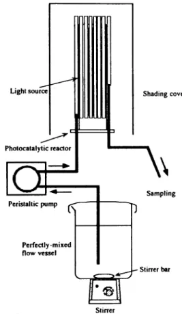
The photocatalytic reactor (volume of the reaction section; 7.22•~10-5m3, substantial length of the reaction section; 5.15m) was set up in the batch-recirculation reactor system shown in Fig 3. An aqueous DNP solution (225•~10-4m3) was poured into the perfectly-mixed flow vessel and then well-mixed with a magnetic stirrer. The DNP solution was circulated between the perfectly-mixed flow vessel and photocatalytic reactor at a flow rate of 2.5•~10-5m3 min4 with a peristaltic
CELSS学 会 誌 VOL.13 NO.2 (2001年3月)
Figure 3. Schematic of a continuous-flow photocatalytic reactor system.
pump. The blacklight fluorescent lamp was switched-on so that the reaction was started. An aliquot of the reaction mixture in the perfectly-mixed flow vessel was taken at appropriate time intervals to measure the absorbance at 357 nm. Although the temperature of the reaction mixture was kept at 30•Ž, the reaction rate in the present system was less dependent on the temperature, like in the other photocatalytic systems.
In the continuous-flow reaction experiment, an aqueous DNP solution of 11.6g m-3 in the perfectly-mixed flow vessel was continuously supplied to the photocatalytic reactor at a constant flow rate. When the time corresponding to five times of the space time passed, the effluent from the reactor was taken to measure the DNP concentration.
4 RESULTS AND DISCUSSION 4.1 Determination of intrinsic kinetic parameters
Figure 4 shows a plot of the initial rates of DNP
decomposition, ƒÒ0/ƒ¿, against the initial DNP concentrations, yb0 The initial rate of DNP decomposition becomes almost constant at an initial
Figure 4. Relationship between initial decomposition rate and initial reactant concentration in decomposition of DNP. The solid line was calculated by a Langmuir-Hinshelwood expression.
DNP concentration above 15g m-3 and we determined the value of k to be 2.78•~10-4g m-2-cat min-1, where the unit "m-2-cat" means the value per unit surface area of the photocatalyst. The experimental data in Fig 4 was further plotted in the form of yb0/(ƒÒ0/ƒ¿) versus yb0, as shown in Fig 5. In the low concentration region, the plot of the experimental data is convex downward due to the influence of film-diffusional resistance. The least-square method was applied to seven data plotted in this
Figure 5. A plot of yb0/(ƒÒ0/ƒ¿) versus y0. The thick solid line and thin straight line were calculated by Eqs .(21) and (41), respectively. The broken Ilne was calculated under the assumption of no diffusional effect .
low concentration region and the following equation was obtained.
(41)
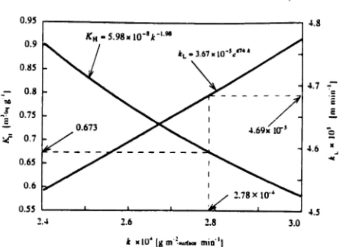
From the slope and intercept of this equation, we determined that kapp=1.36•~10-3g m-2-cat min-1 and KHapp=2.75•~10-2m-3-liq g-1 at yb0ave=2.54•~103g m-3-liq where the unit "m3-liq" means the value per unit volume of the liquid solution. Then, the values of yb0ave and KHapp were used to calculate ƒÀbapp. This calculated value was given to the computer program in which Eqs.(31) and (32) were solved with respect to ƒÁ1 and ƒÁ2 for various values of ƒÓapp changed from 0 to 5 for every step of 0.1. Finally, the plots of KH and kL versus k were obtained from the values of ƒÓapp, ƒÁ1,, and ƒÁ2, as shown in Fig 6.
From these plots, the equations of regression curves were determined as
KH=5.98×10⁻⁸k-1.98 (42)
and
kL=3.67×10⁻⁵e874k
(43) The value of k determined before was inserted into these equations, so that it was determined that KH=0.673
m-3-liq g1 and kL=4.69×10⁻⁵m min4. The lines calculated using the kinetic parameters and mass-transfer coefficient thus determined are shown by a thick solid line in Fig 5. The calculated line is in good agreement with the experimental values, indicating the validity of the parameter values determined above. Figure 5 also includes a broken line, which represents the result calculated in the absence of diffusional resistance, i.e.,ƒÓ
=0 . Since E1 is equal to unity under this reaction condition, the relationship between yb0/(ƒÒ0/ƒ¿) and yb0 becomes linear. On the other hand, there exists a deviation of the thick solid line from the broken line in the low concentration region, clearly showing that the effect of film-diffusional resistance is not negligible in this region, although it is not so remarkable because the value of ƒÓ is at most 4.0 and E1=0.92.
4.2 Decomposition of DNP in a batch-recirculation photocatalytic reactor system
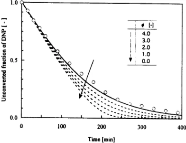
Figure 7 shows the time courses of unconverted DNP fraction in the photocatalytic decomposition of DNP at an initial concentration of 11.6 g m-3 in a batch-recirculation mode (circulation flow rate; 2.5•~10-5 m3
min-1). DNP is exponentially decomposed towards zero concentration. The solid line shows the calculated line
Figure 6. Plots of intrinsic adsorption equilibrium constant and mass-transfer coefficient versus intrinsic kinetic constant.
by the batch-recirculation reactor model, where the calculation was carried out using the values of k, KH, and kL determined in Section 4.1. The calculated line is in fairly good agreement with the experimental values, suggesting the validity of the mathematical model and the method used to determine k, KH, and kL. This calculated line was identical to the result calculated by the batch reactor model, i.e., perfectly-mixed flow reactor model, which clearly shows that the present reaction condition (i.e., batch-recirculation reaction condition) can be approximated by the batch reaction condition. This result can also be understood from the magnitudes of the values of a (=1.39) and b (=0.0588) for the present reaction condition; note that the batch-recirculation reactor model is completely identical to the batch reactor model when a=0 and b=0. In addition, it may be interesting to see how much the system is affected by the diffusional resistance. Under the present reaction condition, the value of ƒÓ is equal to 4 .0. Thus the calculation was made by decreasing the value of from 4.0 to zero. Theoretically, the photocatalytic reaction proceeds more rapidly if the system has a smaller value of and a reaction curve which decreases at a maximum reaction rate is given when ƒÓ =0. In other words , a reactor gives a maximum reaction rate when ƒÓ=0. In Fig.7, there is no surprisingly remarkable difference between the reaction curve at ƒÓ =0 and the experimental data
. This means that the structure of the present photocatalytic reactor holds the diffusional resistance low because the thin glass tube forces the liquid to flow at a high flow rate.
CELSS学 会 誌 VOL.13 NO.2 (2001年3月)
Figure 7. Time courses of unconverted DNP fraction in decomposition of DNP at an initial DNP concentration of 11.6 g m-3 in a photocatalytic
reactor. The solid line was calculated by the mathematical model for a batch-recirculation photocatalytic reactor system.
Figure 8 shows the result of simulation for changes in the unconverted fraction of DNP when the circulation flow rate was decreased under the same reaction condition as in Fig 7, where the calculation was carried out using the values of kp KH, and kL determined in Section 4.1. The decomposition rate of DNP decreases as the liquid flow rate increases. Two reasons are considered for this reduction. Firstly, a decrease in the flow rate increases the film-mass transfer resistance, thereby decreasing the decomposition rate. As described in next section, however, this effect was
Figure 8. Simulation of time courses of unconverted DNP fraction in decomposition. of DNP at an initial DNP concentration of 11.6 g m-3 in a batch-recirculation photocatalytic reactor system.
found to be not remarkable so that the value of kL was fixed at a constant value (4.69•~10-5 m min-1).Secondly,
the frequency at which the reaction mixture contained in the perfectly-mixed flow vessel passes through the photocatalytic reactor becomes small as the flow rate decreases, which reduces the decomposition rate. In other words, the decreased decomposition rate is due to a shift of the batch reaction condition to the batch-recirculation reaction condition. In each reaction curve, the DNP concentration decreases slowly and then acceleratingly. Obviously this is a feature of the batch-recirculation reactions35).
4.3 Decomposition of DNP in a continuous-flow photocatalytic reactor system
Figure 9 shows the relationship between the conversion and liquid flow rate in the decomposition of DNP at an initial concentration of 11.6 g m-3 in a continuous-flow reaction mode. The conversion was exponentially decreased with the increase of the liquid flow rate.
Figure 9 Relationship between conversion and liquid flow rate in decomposition of DNP at an Initial DNP concentration of 11.6 g m-3 in a continuous-flow photocatalytic reactor. The solid line was calculated by the continuous-flow photocatalytic reactor model.
To apply the continuous-flow reactor model to the experimental data in this figure, a variation in kL with the flow rate was investigated and little effect was found. This is probably because the concentration level of DNP is very low. Thus, the calculation of the relationship between the conversion and liquid flow rate by the continuous-flow reactor model was carried out using the value of kL as well as the values of k and KH, determined from the experimental data in the
batch-recirculation reactor system. The calculated result, shown by a solid line in Fig 9, is in fairly good agreement with the experimental values, indicating the validity of the mathematical model. Also, it is suggested that kL has an almost constant value under the experimental condition investigated here.
The results calculated using the continuous-flow reactor model indicates that the analytical method previously proposed in an immobilized-enzyme system is also useful to determine the intrinsic kinetic parameters and mass-transfer coefficient in the present photocatalytic reactor system. Furthermore, the mathematical model that takes into consideration the effect of film-diffusional resistance on the photocatalytic decomposition of DNP is useful to characterize the performance of the photocatalytic reactor system under operation in a batch, batch-recirculation, or continuous-flow mode.
5 CONCLUSIONS
In the present work, a photocatalytic reactor, having a structure of a 6-W blacklight fluorescent lamp surrounded by an annular array of 19 Pyrex glass tubes, was constructed and its performance was investigated in the photocatalytic decomposition of DNP. Furthermore, the experimental data obtained under operation in batch-recirculation and continuous-flow modes were analyzed using their respective mathematical model. As a result, the following conclusions were withdrawn.
1) The intrinsic kinetic constant was determined from the initial reaction rate measured at a high initial reactant concentration. Also, the intrinsic adsorption equilibrium constant and mass-transfer coefficient were determined by the method previously proposed. The result calculated by applying these parameter values to the batch-recirculation reactor system model was in good agreement with the experimental values.
2) At an initial DNP concentration of 11.6 g m-3, at which the batch-recirculation reaction experiment was performed, the catalytic effectiveness factor was equal to 0.92, indicating that the effect of film-diffusional resistance is not so high in the present system.
3) Under the present reaction condition, the batch-recirculation reactor system can be approximately
regarded as the batch reactor system.
4) The photocatalytic decomposition of DNP was slowed down with the decrease of the liquid flow rate, which is considered due to a shift of the batch reaction condition (perfectly-mixed flow condition) to the batch-recirculation reaction condition.
5) A series of the methods previously proposed in an immobilized-enzyme system are also useful to determine the intrinsic kinetic parameters and mass-transfer coefficient in the present photocatalytic reactor system.
6) The mathematical model that takes into consideration the effect of film-diffusional resistance on the photocatalytic decomposition of DNP is useful to simulate the performance of the photocatalytic reactor system operating in batch, batch-recirculation, or continuous-flow mode. Acknowledgment
The authors deeply thank Mr. Go Hirata for his partial assistance in the experiment.
NOTATION
a Ratio of plug-flow reactor and stirred-tank vessel volumes (-)
b Dimensionless number that expresses a relative relationship between reaction rate and reactant flow rate (-)
Cb Dimensionless reactant concentration in a bulk liquid (=yb/yb0) (-)
Ef Effectiveness factor (-) h Stepsize for time (min)
KH Adsorption equilibrium constant (m3 g-1)
k Kinetic constant (g m-2-cat min-1)
kL Mass-transfer coefficient (m min-1)
L Length of a flow path in a photocatalytic reactor (m) Q Recirculation flow rate (m3 min-1)
t Time (min)
uz Liquid flow rate (m min-1) V
p Volume of a fluid in each plug -flow tube or reactor
(m3)
Vr Total volume of a fluid in a plug-flow photocatalytic
reactor (m3) V
a Volume of a fluid in a perfectly-mixed flow vessel
(m3)
υ Reaction rate (g m-3-liq min-1)
CELSS学 会 誌 VOL.13 NO.2 (2001年3月)
y0 Initial reactant concentration (g m-3)
yb Reactant concentration in a bulk liquid (g m-3) yp Reactant concentration in a bulk liquid in a
plug-flow tube (g m-3)
ypa Reactant concentration at photocatalytic surface in a reactor (g m-3)
Z Dimensionless coordinate in a continuous-flow reactor (-)
z coordinate in a continuous-flow reactor (m)
α Ratio of the total surface area of photocatalyst coated on inner surface of a glass tube and the total volume of a reaction mixture
(mm2-cat m-3-liq)
βb Dimensionless reactant concentration in a bulk
liquid (=yp(r)KH) (-)
γ1 Dimensionless kinetic constant (=kapp/k) (-)
γ2 Dimensionless adsorption equilibrium constant
(=KH/KHapp) (-)
φ Modulus (=k KH/kL) (-) μ Variable defined by Eq.(33) (-)
ρ Variable defined by Eq.(7) (-)
τs Space time for a perfectly-mixed flow vessel (min)
ω Dimensionless parameter (=ƒ¿ k KHL/uz) (-)
ξ Variable defined by Eq.(8) (-) <Superscript>
app Apparent value ave Average value
(d) Value in a plug-flow pipe downstream to a plug-flow
reactor
(r) Value in a plug-flow reactor
(u) Value in a plug-flow pipe downstream to a plug-flow
reactor
<Subscript>
b Bulk liquid exp Experimental value
in Value at entrance
out Value at exit
p Value in a plug-flow pipe
a Value in a perfectly-mixed flow vessel
o Value at t=0
REFERENCES
1) Barbeni, M., E. Pramauro and E. Pelizzetti (1984): Phottodegradation of 4-chlorophenol catalyzed by titanium dioxide particles, Nouv. J. De Chim., 8, 547-550.
2) Bideau, M., B. Claudel, L. Faure and H. Kazouan (1991): The photo-oxidation of acetic acid by oxygen in the presence of titanium dioxide and dissolved copper ions, J. Photochem. Photobiol. A: Chem., 61, 269-280.
3) Chen, D. and A.K. Ray (1998): Photodegradation kinetics of 4-nitrophenol in TiO2 suspension, Wat. Res, 32, 3223-3234.
4) Dieckmann, M.S., K.A. Gray and P.V. Kamat (1992): Photocatalyzed degradation of adsorbed nitrophenolic compounds on semiconductor surfaces, Wat. Sci. Tech., 25, 277-279.
5) Driessen, M.D. and V.H. Grassian (1998): Photooxidation of trichloroethylene on Pt/TiO2, J. Phys. Chem. B, 102, 1418-1423.
6) Fu, X., W.A. Zeltner and M.A. Anderson (1995): The gas-phase photocatalytic mineralization of benzene on porous titania-based catalysts, Appl. Catal. B: Environ., 6,209.224.
7) Harada, K., T. Hisanaga and K. Tanaka (1987): Photocatalytic degradation of organophosphorus compounds in semiconductor suspension, New J. Chem., 11, 597-600.
8) Izumi, I.,W.W. Dunn, K.O. Wilbourn, F.-R. F. Fan and A. J. Bard (1980): Heterogeneous photocatalytic oxidation of hydrocarbons on platinized T102 powders, J. Phys. Chem., 84, 3207-3210.
9) Kormann, C,D.W. Bahnemann and M.R. Hoffmann (1991): Photolysis of chloroform and other organic molecules in aqueous T103 suspensions, Environ. Sci. Technol., 25, 494-500.
10) Matthews, R.W. (1986): Photo-oxidation of organic material in aqueous suspensions of titanium dioxide, Wat. Res., 20, 569-578.
11) Matthews, R.W. (1987): Photooxidation of organic impurities in water using thin films of titanium dioxide, J. Phys. Chem, 91, 3328-3333.
12) Mazzarino, I. and P. Piccinini (1999): Photocatalytic oxidation of organic acids in aqueous media by a supported catalyst, Chem. Eng. Sci., 54, 3107-3111. 13) Sabate, J., M. A. Anderson, H. Kikkawa, M. Edwards
and J.C.G. Hill (1991): A kinetic study of the photocatalytic degradation of 3-chlorosalicylic acid over TiO2 membranes supported on glass, J. Catal.,
127, 167-177.
Photocatalytic degradation of phenol by TiO2 aqueous dispersions: Rutile and anatase activity, New J. Chem, 14, 265-268.
15) Serrano, B. and H. de Lasa (1999): Photocatalytic degradation of water organic pollutants: pollutant reactivity and kinetic modeling, Chem. Eng. Sci., 54, 3063-3069.
16) Zhao, M.,S. Chen and Y. Tao (1995): Photocatalytic
degradation of organophosphorus pesticides using this films of TiO2, J. Chem. Tech. BiotechnoL, 64, 339-344.
17) Matthews, R.W. (1987): Solar-electric water purification using photocatalytic oxidation with TiO2 as a stationary phase, Solar Energy, 38, 405-413. 18) Jackson, N.B., C.M. Wang, Z. Luo, J. Schwitzgebel,
J.G. Ekerdt, J.R. Brock and A. Heller (1991): Attachment of TiO2 powders to hollow glass
microbeads: activity of the TiO2-coated beads in the
photoassisted oxidation of ethanol to acetaldehyde, J. Electrochem. Soc., 138, 3660-3664.
19) Vorontsov, A.V., E.N. Savinov, G.B. Barannik, V.N. Troitsky and V. N. Parmon (1997): Quantitative
studies on the heterogeneous gas-phase
photooxidation of CO and simple VOCs by air over TiO2 Catal. Today, 39, 207-218.
20) Shiraishi, F., K. Toyoda, S. Fukinbara, E. Obuchi and K. Nakano (1999): Photolytic and photocatalytic treatment of an aqueous solution containing microbial cells and organic compounds in an annular-flow reactor, Chem. Eng. Sci., 54, 1547-1552. 21) Obuchi, E., T. Sakamoto, K. Nakano and F. Shiraishi
(1999): Photocatalytic decomposition of acetaldehyde
over TiO2/SiO2 catalyst, Chem. Eng. Sci., 54,
1525-1530.
22) Matsunaga, T., R. Tomoda, T. Nakajima, N. Nakamura and T. Komine (1988): Continuous-sterilization system that uses photosemiconductor
powders, Appl. Environ. Microbiol., 54, 1330-1333.
23) Yamazaki-Nishida, S., K.J. Nagano, L.A. Phillips, S.
Cervera-March and M.A. Anderson (1993):
Photocatalytic degradation of trichloroethylene in the gas phase using titanium dioxide pellets, J. Photochem. Photobilol. A: Chem., 70, 95-99. 24) Peral, J. and D.F. Ollis (1992): Heterogeneous
photocatalytic oxidation of gas-phase organics for air purification: acetone, 1-butanol, butylaldehyde,
formaldehyde, and m-xylene oxidation, J. CataL, 136, 554-565.
25) Obee, T.N. and R.T. Brown (1995): TiO2 photocatalysis for indoor air applications: Effects of humidity and trace contaminant levels on the oxidation rates of formaldehyde, toluene, and 1,3-butadiene, Environ. Sci. Technol., 29, 1223-1231. 26) Engasser, J.-M. and C. Horvath (1973): Effect of
internal diffusion in heterogeneous enzyme system: evaluation of true kinetic parameters and substrate diffusivity, J. theor. Biol., 42, 137-155.
27) Lortie, R. and D. Thomas (1986): Heterogeneous one-dimensional model for fixed bed enzyme reactors. Biotechnol. Bioeng., 28, 1256-1260.
28) Matthews, R.W. (1988): Kinetics of photocatalytic oxidation of organic solutes over titanium dioxide, J. Catal., 111, 264-272.
29) Shiraishi, F., (1997): Computational methods for analysis of immobilized enzyme reactions: from reaction kinetics to reactor-design methods, Corona Publishing Co., Ltd., Tokyo,
30) Shiraishi, F. (1990): Substrate concentration dependence of apparent maximum reaction rate and apparent Michaelis constant observed in immobilized enzyme reactions, Kagaku Kogaku, 16,
123-129.
31) Hasegawa, T. and F. Shiraishi (1994): A graphical method for estimating intrinsic kinetic parameters from apparent values in an immobilized enzyme system, in First Asian Control Conference 1994. Tokyo: Committee of Asian Control Conference. 32) Hasegawa, T., F. Shiraishi and H. Nagasue (2000):
Numerical tests of usefulness of power-law formalism method in parameter optimization problem of immobilized enzyme reaction, J. Chem. Eng. Jpn, 33, 197-204.
33) Shiraishi, F., H. Miyakawa, T. Hasegawa and S. Kasai (1996): A computational method for determination of the mass-transfer coefficient in packed-bed immobilized enzyme reactors, J. Chem. Tech. Biotechnol., 66, 405-413.
34) Shiraishi, F., T. Hasegawa, S. Kasai, N. Makishita and H. Miyakawa (1996): Characteristics of apparent kinetic parameters in a packed-bed immobilized enzyme reactor, Chem. Eng. Sci, 51, 2847-2852. 35) Fukinbara, S., F. Shiraishi and H. Nagasue (2000): A
CELSS学 会 誌 VOL.13 NO.2 (2001年3月)
systems and its numerical calculation method , CELSS J., 12, 9-18.
36) Fukinbara, S., F. Shiraishi and K. Nakano (2000): Characteristics of the photocatalytic reactor with an annular array of glass tubes surrounding a light source: 1. selection of a light source and photocatalyst support, CELSS J., 14, 1-10.
37) Shiraishi, F. (1995): Diffusional and electrostatic effects on apparent kinetic parameters of reactions catalyzed by enzyme immobilized on the external surface of a support, J. Ferment. Bioeng., 79, 373-377. 38) Atkinson, K., (1993): Elementary Numerical Analysis,
John Wiley & Sons, Inc., New York.
39) Shiraishi, F. (1993): Experimental evaluation of the usefulness of equations describing the apparent maximum reaction rate and apparent Michaelis constant of an immobilized enzyme reaction, Enzyme Microb. Technol., 15, 150-154.
40) Shiraishi, F. and H. Miyakawa (1994): Influences of nonuniform activity distributions on the apparent maximum reaction rate and apparent Michaelis constant of immobilized enzyme reactions, J. Ferment. Bioeng., 77, 224-228.