Japan Advanced Institute of Science and Technology
JAIST Repository
https://dspace.jaist.ac.jp/Title
A simple near-capacity concatenation scheme over
MISO channels
Author(s)
Tran, Nghi H.; Le-Ngoc, Tho; Mastumoto, Tad;
Nguyen, Ha H.
Citation
Sixth International Conference on Broadband
Communications, Networks, and Systems, 2009.
BROADNETS 2009: 1-7
Issue Date
2009-09
Type
Conference Paper
Text version
publisher
URL
http://hdl.handle.net/10119/9106
Rights
Copyright (C) 2009 IEEE. Reprinted from Sixth
International Conference on Broadband
Communications, Networks, and Systems, 2009.
BROADNETS 2009. This material is posted here with
permission of the IEEE. Such permission of the
IEEE does not in any way imply IEEE endorsement
of any of JAIST's products or services. Internal
or personal use of this material is permitted.
However, permission to reprint/republish this
material for advertising or promotional purposes
or for creating new collective works for resale
or redistribution must be obtained from the IEEE
by writing to [email protected]. By
choosing to view this document, you agree to all
provisions of the copyright laws protecting it.
A Simple Near-Capacity Concatenation Scheme
Over MISO Channels
Nghi H. Tran, Tho Le-Ngoc, Tad Mastumoto, and Ha H. Nguyen
Abstract- This paper proposes a capacity-approaching, yet simple scheme over a multiple-input single-output (MISO) wire-less fading channel, which is very common in the downlink of a cellular system. The proposed scheme is based on a concatenation of a mixture of short memory-length convolutional codes or repetition codes and a short, and simple rate-l linear block code, followed by either I-dimensional (I-D) anti-Gray or Gray mapping of quadrature phase-shift keying (QPSK) modulation. By interpreting rate-l code together with I-D mapping as a multi-D mapping performed over multiple transmit antennas, the error performance is analyzed in the turbo pinch-off region using EXIT chart. At first, a simple design criterion on the bit-wise mutual information with perfecta priori information is derived. Based on the obtained design criterion, an optimal rate-l code for each I-D mapping is then constructed to maximize the bit-wise mutual information with perfecta priori information. The combination of optimal rate-l code and I-D mapping results in a steep inner detector's EXIT curve over an MISO channel, which matches very well to that of a simple outer code. It is demonstrated that the simple concatenation scheme can achieve a near-capacity performance over the MISO channels. In some cases, the selected mixed code is just a simple repetition code.
Index Terms- Multiple-input single-output (MISO) channels, capacity-approaching performance, EXIT chart, convolutional code, repetition code, block code.
I. INTRODUCTION
It is widely known that the use of multiple antennas signif-icantly enhances the error performance of a wireless system [1], [2]. With the recent developments in iterative decoding, a number of pragmatic approaches using powerful turbo-like codes have been proposed [3], [4] to achieve a close-capacity performance under a bit-interleaved coded modulation (BICM) framework [5], [6]. For instance, by using a turbo code as an outer code, it was shown in [3] that a near-capacity performance can be attained in a symmetric antenna setup where the number of receive antennas equals the number of transmit antennas. This result also holds in an antenna setup where the number of receive antennas is greater than the number of transmit antennas.
This work was supported in parts by the Natural Sciences and Engineering Research Council of Canada (NSERC), and by the Japanese government funding program, Grant-in-Aid for Scientific Research (B), No. 20360168.
Nghi H. Tran and Tho Le-Ngoc are with the Department of Electrical & Computer Engineering, McGill University, Montreal, Quebec, Canada. Email: [email protected], [email protected].
Tad Mastumoto is with Japan Advanced Institute of Science and Technol-ogy, Japan, and Center for Wireless Communication at University of Oulu, Finland. Email: [email protected].
Ha H. Nguyen is with the Department of Electrical & Computer Engineering, University of Saskatchewan, Saskatchewan, Canada. Email: [email protected].
Digital Object Identifier: 10.410B/ICST. BROADNETS2009.7271
http://dx.doi.org/10.410B/ICST.BROADNETS2009. 7271
In a practical wireless system, it might not be feasible to implement multiple antennas at both the transmitter and receiver. It is due to the reason that a multiple-antenna system requires multiple radio frequency chains and low-noise ampli-fiers, which is very costly. Furthermore, in some applications such as the downlink of a cellular system, it is physically not possible to place multiple antennas on a small handset. Under this antenna configuration, the design for a capacity-approaching system is much more challenging. For example, it was observed in [7], [8] that the error performance of a coded system using turbo codes or low-density parity check (LOPC) codes optimized for the binary-input channels experiences a severe degradation when the antenna setup is asymmetric, e.g., there is only a single antenna at the receiver. The problem can be overcome by using orthogonal space-time block codes in order to transfer a multiple antenna channel into single-input single-output channels [8]. Unfortunately, a complex orthogonal design with full transmission rate does not exist for more than two transmit antennas. Recently, by using a very well-design irregular LOPC code followed by Gray map-ping with QPSK, reference [4] proposes a coded modulation scheme that performs very close to the capacity limit in the asymmetric antenna setup with four transmit antennas. Using a similar approach as in [4], equally good performances are also obtained in [9] by using outer irregular repeat accumulate (RA) codes. To our knowledge, the designs in [4], [9] are still the most effective coded modulation techniques for near-capacity performance over wireless fading channels under the asymmetric antenna configuration.
As an alternative, this paper proposes a simple yet effec-tive concatenation scheme with QPSK over an asymmetric multiple-antenna channels in which multiple antennas are only equipped at the transmitter. This antenna configuration is very common in the downlink of a cellular system. The proposed system is based on a simple serial concatenation of a mixture of short memory-length convolutional codes or repetition codes and a short rate-l linear block code and applicable for both 1-0 anti-Gray or Gray mapping. By interpreting rate-l code together with 1-0 mapping as a multi-D mapping em-ployed over multiple transmit antennas, the error performance is analyzed in the turbo pinch-off region for a close-capacity performance using extrinsic information transfer (EXIT) chart [4], [10], [11]. In particular, a simple design criterion on the bitwise mutual information with perfect a priori information is first developed. This derivation allows us to determine optimal rate-l linear block codes for anti-Gray and Gray mappings to maximize the bitwise mutual information with perfect a priori information. The most suitable outer mixed codes are
2 b. Receiver II . SYSTEM MODEL (1) b=G·v.
I:
[ex
p(_llr -
~o'
sW)
sE'l' t.II
P(Vj=
Vj(s)j1)] .
(3) j # P(Vk=
b;0) B. ReceiverConsider an ergodic frequency-flat Rayleigh fading channel. The received signal r is given as:
r
=
hT . S+
n. (2) In (2), the vector h is an N; x I complex vector known perfectly at the receiver and its components areCN(o,
I? Furthermore, n isCN(O,
No) representing additive white Gaussian noise (AWGN).At the receiver, a typical concatenation of a conventional detector, a posteriori probability (APP) bit decoder of rate-I block code, and a soft-input soft-output (SISO) outer decoder can be applied. Similar to the design in [9], the detector and rate-I block decoder can be combined in one block as shown in Fig. 1 (b) to reduce decoding complexity and improve robustness. More specifically, by representing rate-I block code and I-D mapping as a multi-D mapping ~, the optimal combined detector performs APP detection to provide the extrinsic probability of the k coded bitVk , I ::; k ::;Q,being
set atb,bE
{a,
I}, as:In (1), all operations are defined over GF(2). The linearity of G is to guarantee that there is one-to-one correspondence between
v
and b. Then two consecutive bits (b2i-i,b2i), I ::; i ::;Nt, are grouped together and mapped to a complex QPSK symbols,using either I-D anti-Gray or Gray mapping. A sequence of N, 1-D complex symbols{Si}
is considered to be a super symbol S=
[SI, S2 , . . . ,s N,lT in an NrD constellation 'Ii with cardinalityl'lil
=
2Q .Each componentS i is finally transmitted by the ith transmit antenna.
The combination of rate-I linear block code and I-D mapping above can be interpreted as a special case of multi-D mapping technique in which a vector of
Q
binary bitsv
=
[Vi ,V2 , .. " vQ]T are mapped directly to a super symbolSaccording to some multi-D mapping rule [20], [21]. Hereafter, vector
v
is referred to as the label ofs.
The optimal choices of rate-I code as well as an outer mixed code for a near-capacity performance shall be discussed shortly in the next section. of a single outer convolutional or repetition code is a special case of the proposed mixed code.After being interleaved, each group of
Q
=
2Nt coded bits of interleaved sequencec,
denoted asv
=
(Vi,V2, . . . , V Q )T,is fed to a simple rate-I linear block code with generator matrix G of size
Q
xQ
over Galois filed 2 (GF(2)). The design of this rate-I code is discussed in the next section. A vector ofQ output coded bitsb=
(bi ,b2 , .• . ,bQ )T is givenas: Rate-1 code of size0= 2N, ,-- - - - -.j,- - - --, :V1
8
bl: 1· Dmapping- ." 1 y :V2 b~ I I ' I G : : . _, I . I . I : : : 1-Dmapping -SN/Nt : I . , I :VQ b~ : - - - I I I I I Channelr---
J
a. Transmitter P(c ;1) Com bined Detector:---1
I I I I I I I I I I I I IFig. 1. The proposed concatenation scheme equipped with N, transmit antennas and one receive antenna.
A. Transmitter
A block diagram of the transmitter of the proposed con-catenation system equipped with
N,
>
I transmit antennas and N;=
I receive antenna is depicted in Fig. 1(a)' :First, a binary information block U of length Lu is divided intotwo binary sequences U1 and utt of lengths L1 and L n ,
respectively. Each sequence Ul ,l E
{I ,
II}, is encoded by a suitable rate-kl/nl binary encoder into a coded sequence Cl consisting of7}=
L1nl/klcoded bits. These binary encoders could be simple convolutional or repetition codes and shall be determined later. A coded sequenceCof lengthT;
=
T1+
T1 Iis then constructed by serially combining coded sequences
C1 and
en-
This encoding structure, inherited from the codedoping technique proposed in [18], [19], is referred to as a mixed code of K
=
2 binary codes, with code doping ratio a=
L1/
Lu .As shall be shown later, this mixed code providesa flexible structure to control the convergence behavior of the system. Note that the number of binary encoders can be straightforwardly generalized toK
>
2. Furthermore, the use then selected to match to the inner detector with a steep-slope EXIT curve. Analytical and simulation results indicate that the simple concatenation scheme approaches near-capacity. In some cases, the selected mixed code is just a simple repetition code.It should be noted that this paper assumes the ergodic fading channel and only the receiver but not the transmitter knows the channel. Furthermore, as similar to [3], [4], a direct transmission over multiple transmit antennas is considered without the use of special multiple-antenna code-design such as space-time codes [12]-[15]. It is certainly interesting to further extend the technique proposed in this paper to cover both spatial and temporal domains.
lIn [16], [17], we have generalized the scheme to an asymmetric antenna setup in which Nt >NT '
2HereCN(o,(j2) denotes a circularly symmetric complex Gaussian ran-dom variable with variance (j2/2 per dimension.
In (3),
wi
denotes a subset of '11 that contains all symbols whose labels have the valuebat the kth position. Clearly,wi
is determined by the mapping rulee.
Furthermore, vj (s) is the value of the jth bit in the label of sandP(Vj=
Vj(s); I) is the a priori probability of the other bits, ji=
k, on the same channel symbol. Observe that the computation of the extrinsic information of the coded bit in (3) involves the set of 2Q-1super symbols in
wi,
which has the same complexity as that of the conventional detector [3], [4].After being deinterleaved, the extrinsic information of the corresponding T1 and TIl coded bits computed by the
com-bined detector is forwarded to the two SISO channel decoders, respectively. For convolutional codes, the SISO channel de-coder uses the forward-backward algorithm [22], [23]. If the binary encoder is a rate-1 /n repetition code, the extrinsic information for each coded bit is simply calculated as:
n
P(ci=b;O)=
II
P(cj=b;I). (4)j=l,ji=i
There is an iterative processing between the combined detector and the outer channel decoder to exchange the extrinsic information of the coded bits P(v;0) and P(c;0). After being interleaved, P(v;0) and P(c;0) become the a priori information P(c;I) and P(v;I) at the input of the SISO de-coder and the combined detector, respectively. The a posteriori probabilities of the information bits can also be computed to make the hard decisions at the output of the decoder after each iteration.
III. DESIGN USING EXIT CHARTS
In order to examine whether an iterative demodulation and decoding system can achieve near-capacity, one needs to take into account the convergence behavior in the turbo pinch-off, or water-fall, region, where a significant BER decrease is observed over iterations (please see [24] and references therein for detailed discussions). This section analyzes the convergence property of the proposed scheme at the turbo pinch-off region by means of extrinsic information transfer (EXIT) chart [10]. Following the same notations as in [10], let IAI and lEI denote the mutual information between the a priori LLR and the transmitted coded bit, and between extrinsic LLR and the transmitted coded bit at the input and output of the detector, respectively. Similarly, let I E2 and I A2 be the mutual information representing the a priori knowledge and the extrinsic information of the coded bits at the input and output of the SISO decoder. After being deinterleaved, the extrinsic output of the detector is used as the a priori input to the decoder, i.e., IA2
=
lEI. Furthermore, after being interleavered, the extrinsic information of the decoder becomes the a priori information to be provided to the detector, i.e., IAI=
IE2.In the following, with the representation of rate-l linear block code together with I-D mapping as a multi-D mapping
e,
a simple design criterion on the bit-wise mutual information with perfect a priori information lEI (IA I=
1) is first derived. An optimal rate-l linear block code is further developed for each I-D mapping to maximize lEI (IAI=
1). The differenceDigital Object Identifier: 10.410B/ICST.BROADNETS2009.7271 http://dx.doi.org/10.410B/ICST.BROADNETS2009. 7271
between the conventional detector with Gray mapping em-ployed in coded modulation systems using powerful turbo-like codes [3], [4], [8], [9] and the combined detector considered in this paper is then demonstrated with the aid of EXIT curves. Finally, a combination of the combined detector and a mixture of simple convolutional or repetition decoders, with which close-capacity performance can be achieved, is proposed by having the combined detector EXIT curve matched to the decoder EXIT curve. We only consider the same rate-l/2 component codes, which results in an overall rate rc
=
1/2outer mixed code. The analysis and design can be straightfor-wardly extended to other code rates. The ratio of energy per information bit at the receiver over noise power, Eb/No, is defined as [3], [4]:
where E; is total energy used over N; transmit antennas.
A. Bitwise Mutual Information with Perfect A Priori Informa-tion of the Combined Detector
For a given constellation '11 and mapping rule
e,
the bitwise mutual information with perfect a priori information lEI (IAI=
1) can be calculated as follows:where Ik(s,p) is the average mutual information of a BPSK-like constellation consisting of two signal points sand p whose labels differ in only 1 bit at position k. Due to the symmetry of a BPSK-like constellation, the conditional Ik(s,p)lhfor a given channelization h can be expressed as:
[ 1
r
(1Ir-hT.SI12)
Ik(s,p)lh = 1 - ('rrN
o)JrEcexp - No
(
(
1Ir - hT. sI12- llr - hT.PI12) )
]
x log 1
+
exp No dr ·(7) By using the symmetric cut-off rate and Jensen inequality as similar to the analysis in [25], Ik(s,p) can be approximated as:
By substituting Ik( s, p) from (8) into (6), it can be seen that an optimal mapping rule
e
that maximizes lEI (IA I=
1) is the mapping in which two signal points sand p whose labels differ in only 1 bit should be placed as far apart as possible in terms of the Euclidean distance. In the next subsection, in combining with either anti Gray or Gray mapping, an optimal rate-l code is introduced to maximize lEI (IA I=
1).for at least
iN, -
1) values of i, 1 :::;i :::;Nt.Proof: Consider two symbols s
=
[Sl, ... ,SNt]T and p=
[PI, ...,PNt]T whose labels v and y differ in only 1 bit at
position k. Also, let b
=
W .v and a=
W .y. It then follows that:bEBa
=
W· (vEBy)=
Wk. (12)Since W is optimal, lis - pl12
2::
4(Q - 1). Equivalently, IIs, - Pi11 2=
8 for at least iN; - 1) values ofi, 1 :::;i :::; Nt. Furthermore, from (10), one has:Iisi - Pi112 4 ((b2i-1 - a2i_l)2
+
((b2i-1EBb2i ) - (a2i-l EBa2i))2) . (13) B. Optimal Rate-1 Linear Block CodesWithout loss of generality, assume that the coordinates of the four QPSK symbols are
[+1, +1], [+1, -1], [-1, +1],
and [-1,-1]. By representing the super constellation \II as a hypercube in Nt-D signal space, it was shown in [20] that for any symbol s, there is only one symbol p at the largest squared Euclidean distance4Q to s.Furthermore, there are Q symbols {p} at the second largest squared Euclidean distance 4(
Q -
1) to s. This implies the following upper bound onlEI(IA!
=
1):IE! (IA! =
1)
<
1 -
~
[log ( 1 +
N::-
Q )+
(Q-1)log(1+
No:~-l)]
.(9)It is simple to see that a mapping rule
e
that satisfies the following condition achieves the equality in (9):Condition 1:For any symbol s E \II, let \IIs be a set of
Q
symbols {p} whose labels differ in only 1 bit to that of s. In \IIs» there are one symbol at squared Euclidean distance 4Q
and
(Q -
1)symbols at squared Euclidean distances 4(Q -
1) to s.When combining with an 1-D mapping, a rate-1 code G is called optimal if it is linear and the combination leads to a multi-D mapping
e
that satisfies Condition 1. In the following, this optimal code is determined for both anti-Gray and Gray mappings. For convenience, the notations Wand F are used to indicate rate-1 code for anti-Gray and Gray mappings, respectively.1) Optimal codes for anti-Gray mapping: When anti-Gray mapping is used, it is straightforward to verify that a group of 2 binary bits (b2i-1 ,b2i ) , 1 :::; i :::; Nt, shall be mapped to a
QPSK symbol s,
=
[2(b2i-1 EBb2i ) - 1,2b2i-1 - 1,], whereEB denotes GF(2) addition. As a result, a symbol s E \II with label v carrying
Q
bits b, b=
G .v, can be represented as: s=
[2(b1EBb2)-1,
2b1-1, ...
,2(bQ - 1EBbQ )-1,
2bQ - 1_l]T.(10) One then has the following theorem concerning the optimal W.
Theorem 1: LetWk
=
[Wl,k, ... , WQ,k]T be the kth column ofW. If W is optimal then[W2i-l,k, W2i,k]
=
[1,0]
(11)4
It can be observed from (13) that IIs, - Pi11 2
=
8 if and only if[b2i-1EBa2i-l,b2i EBa2i]
=
[1, 0].
Combining this result with (12) proves Theorem 1.Based on Theorem1,the next theorem provides an optimal W for anti-Gray mapping.
Theorem 2: For anti-Gray mapping, the entries of the optimal rate-1 block code Ware given as:
[W2i-l,k, W2i,k]
=
[1,0],
k=
1, 1<
i<
Nt[1, 0],
1
<
k<
Q,
i =1= (k+ 1)
div 2,1
<
i<
Nt[0,1],
1
<
k<
Q,
k mod 2=
0,
i=
(k+ 1)
div 2[1,1]'
1
<
k :::;Q,
k mod 2=
1,
i=
(k+ 1)
div 2 (14)Proof: The linear property of W can be proved as follows. Let m
=
[ml, ... ,mQ]T be a vector ofQ
binary bits and m=
ml EB m2 EB ... EB mQ. Consider the following linear combination:x
=
mlWl EBm2W2EB ... EBmQwQ. (15)It then follows from (14) that:
x
=
[m EBm2, m2, ... ,m EBm2i,m2i-l EBm2i,... ,mQ,mQ_IEBmQ]T. (16)
Therefore, x
=
0 if and only if m=
O. As a result, W is linear.The optimality ofW then follows readily from Theorem 1. In particular, let sand p be two symbols whose label differ in only 1 bit at position k.Consider two separate cases ofk as follows:
• If k
=
1, it can be verified that Iisi - Pi11 2=
8 for all1 :::;i :::; Nt. This makes lis - pl12
=
4Q• If k
>
1, Iisi - Pil1 2=
8 for all 1 :::; i :::; N; but i=
(k
+
1)div 2. When i=
(k+
1)div 2, it follows from (14) and (13) that Iisi -Pi11 2=
4. Therefore, Ils-pl12=
4(Q - 1).Theorem2is thus proved.
Besides the optimal W in (14), it is worth noting that by permuting any two columns of W, another optimal code can be also obtained. The proof is straightforward and omitted here for brevity of the presentation.
2) Optimal codes for Gray mapping: For a given optimal W in (14), define F as a
Q
xQ
matrix over GF(2) whose elements are:{ !2i-l,k!2i,k
=
=
W2i-l,kW2i-l,kEBuiu» (17) The following theorem states the optimality of F.Theorem 3: The use of rate-1 code F in (17) together with Gray mapping results in the same mapping rule
e
attainted by combining rate-1 code W in (14) and anti-Gray mapping. Consequently, F in (17) is optimal for Gray mapping.Proof: Let v be a vector of binary inputs. When W in (14) is used together with anti-Gray mapping, a symbol s E \II with label v carrying
Q
bits b, b=
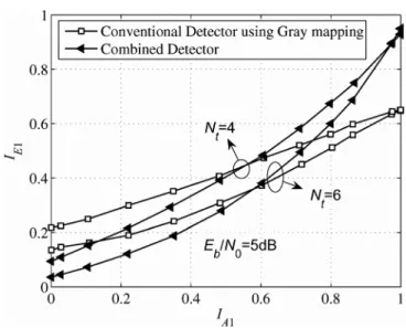
G .v, is given in (10). On the other hand, with rate-1 code F followed by Gray mapping, aFig. 2. The MIMO detector and combined detector EXIT curves at
Eb / NO=5dB.
- 0 -Conve ntional Detector using Gray mapping
-+-
Co mbined Detector symbol p E '1'carryingQ
bitsa, a=
F ·v, can be expressedas:
p
=
[2al - 1,2a2 - 1, ... ,2aQ-l - 1,2aQ - I]T. (18) From (17), one has:{
a2i-l
=
f(2 i-l) . v=
(W(2i-l) EBW(2i») . v=
b2i - 1EBb2i a2i=
f(2t-l) . V=
W(2t-l) .V=
b2i - 1(19) where f(k) and w(k) are the kth rows ofF and W , respec-tively. It then follows from (10), (18), and (19) that s
=
p .It means that a combination of either F and Gray mapping or Wand anti-Gray mapping leads to the same mapping rulee.
Theorem 3 is proved.Combining the above results, it can beconcluded that the combination of rate-l code W in (14) followed by anti-Gray mapping is equivalent to the combination of rate-l code F in (17) and Gray mapping . Furthermore, these combinations maximize
let
(fAt
=
1) .0.8
0.6
0.4
0.2 0.4 0.6 0.8
Fig. 3. EXIT curves of the combined detector withNt = 4 transmit antennas atEb /NO=7 .55dB,the ll2, 2-state convolutional code (cc), and the rate-l/2 repetition code.
C. EXIT Curves of the Conventional and Combined Detectors Figure 2 shows EXIT curves of the conventional detector using Gray mapping and combined detector at Eb/No
=
5dB withN;=
4 andN;=
6 transmit antennas . For a conventional detector with Gray mapping, the EXIT curve exhibits a steep slope. This phenomenon causes a performance degradation when Gray mapping is used together with turbo codes [4], [7]. In the case of the combined detector, it canbeseen that the bitwise mutual information with perfect a priori information IE. (IA •=
1) can be significantly improved over that ofthe conventional detector. However, since the proposed block codes are of rate 1, the areas under the EXIT curves of the combined detector and conventional detector must be equal [26]. Consequently, it can be observed from Fig. 2 that the combined detector 's EXIT curve exhibits even much higher slope over that of the conventional detector, with a very large mutual information at the right end of the curve. As shown in the next subsection, this makes the combination of either rate-1 code W in (14) with anti-Gray mapping or rate-l code F in (17) with Gray mapping a perfect match to a simple outer mixed codes, which also have decayed EXIT curves. More interestingly , near-capacity performance canbeachieved .
0.8 0.6 _ Lll N _ "": 0.4 0.2 -+- Nt4 , E/N
o
=7.55dB - - rate 1/2, 2-state cc,_._ , rate 1/2, repetition code 0.8
D. EXIT Curve Matching
This subsection applies EXIT chart technique [10] to select a suitable mixed code for the combined detector. By using EXIT charts, both EXIT curves of the combined detector and decoder are placed in the same graph, but the axes of the EXIT curve of the decoder are swapped [10] so that the convergence behavior of the concatenation scheme can be well visualized. It should be mentioned that for the system under consideration, the EXIT curve of a rate-r emixed code does not depend on SNR and always crosses the middle point (0.5 ,rc ) [10].
We first examine the case with N,
=
4 as similar to [4]. Figure 3 plots the EXIT curve of the combined detector at Eb /No=7.55dB and the EXIT curves of two simple rate-l/2 codes , a 2-state convolutional code with generator polynomialsDigital Object Identifier: 10.4108/1CST.BROADNETS2009.7271 http://dx.doi.org/10.41081ICST.BROADNETS2009.7271
gl
=
[1,1] and g2=
[1,0] , and a repeution code. Note that the rate-l/2 repetition code is the simplest possible code, whereas the rate-l/2 2-state convolutional code is the simplest convolutional code . The above SNR is chosen to make sure that the middle point of the detector EXIT curve IE. (0.5) is larger than 0.5 . It is clear from Fig. 3 that the EXIT curve of the standard rate-l/2, 2-state convolutional code does not fit well to the detector EXIT curve, since the two EXIT curves quickly intersect and the intersection point falls in the lower left quadrant of the EXIT plane . Because the EXIT curve of a more powerful rate-l/2 convolutional code exhibits a sharper slope at the beginning, it is straightforward to see that there does not exist any suitable rate-l/2 convolutional code for the system . The EXIT curve of rate-l/2 repetition code intersects the combined detector EXIT curve in the upper right quadrant6
of the EXIT plane, but at a low mutual information, which does not guarantee low BER.
Fig. 4. EXIT charts of the combined detector withN ,= 4 atEb /NO=7 .55dB
and a rate-II2 mixed code of 2-state cc and repetition code with code doping ratioa= 0.8.
IV. ILLUSTRATIVE RESULTS
This section provides simulation results to verify the anal-ysis made in the previous sections and to demonstrate the excellent performance achieved by the proposed systems. A random interleaver of length 3 x 10⁵ is used for all systems
under consideration. Each point in the BER curves is simulated with 6 x 10⁶ to 109coded bits.
In the case of using a larger number of transmit antenna, it can be seen from Fig. 2 that the combined detector EXIT curves experience much higher slope. This suggests that even a simpler code could be used for a good convergence. In par-ticular, Fig. 5 shows the EXIT curve of the combined detector when Nt=6 at Eb/No= I 1.28dB. Note that the corresponding capacity limit is atEb/NO=lO.77dB. Also plotted in Fig. 5 is the EXIT curve of a rate-I/2 repetition code. Itis observed from Fig. 5 that the combined detector EXIT curve of the Nt=6 setup fits well to that of the rate-1I2 repetition code,
which is the simplest possible code. More impressively, this curve match is achieved at only O.5dB away from the capacity limit.
Similar results are also obtained when the number of transmit antenna increases. Those results are, however, omitted here for brevity of the presentation.
0.8
-+- Nt=4, E/No=7.55dB
- - rate 1/2, mixed code, a=0.8 0.2 0.8 0.6 _ L.l.l N
-"
0.4 0.2 0 0Fig. 5. EXIT charts of the combined detector with Nt 6 at
Eb /No=11.28dB and a rate-l/2 repetition code.
10-1 0:: 10-2 [.lJ co 10-3 ~ x "l" 10-4 6 8 10 12 14 Eh/No(dB) 10° . - - - , - - - -,---,---,
Figure 6 plots the BER performance with 50 iterations of the 6 x 1 and 4 x 1 systems. The corresponding outer codes for the two systems are the rate-1I2, repetition code and the rate-I/2 mixed code comprised of the rate-1I2 standard 2-state convolutional code and the rate-1I2 repetition code with a
=
0.8. The spectral efficiency for each system is therefore 6 bits/channel use and 4 bits/channel use, respectively. It can be seen from Fig. 6 that the analytical results obtained by EXIT charts agree with the BER curves. In particular, the turbo pinch-off region happens aroundEb/NO=7.8dB and Fig. 6. BER performances with 50 iterations of the proposed systems equipped withNt = 6 and N ,= 4 transmit antennas, andN; = 1 receive antenna. The outer codes are rate-1I2, repetition code and rate-l/2 mixed code of rate-1I2 standard 2-state convolutional code and rate-l/2 repetition code witha= 0.8, respectively.0.8
-o- Nt6, E/No= 1I. 28dB , _. - ' rate 1/2, repetition code 0.2 0.8 0.6 _ L.l.l N
-"
0.4 0.2To overcome the above disadvantages, a mixed code of the two above codes can be used to achieve better curve matching. In particular, Fig. 4 shows the EXIT curve of the combined detector atEb/N
o
=
7.55dB and the EXIT curve of a mixture of 2-state convolutional code (cc) and repetition code with code doping ratio a=
0.8. It is interesting to see that the EXIT curve of this mixed code matches very well to the detector EXIT curve. The two EXIT curves do not intersect until reaching the ending pointfA l(1)with very high mutualinformation, leading to a low BER. This match is very similar to that obtained in [4], [9] using an irregular LDPC or RA code and Gray mapping alone. Furthermore, this curve fit happens close to the capacity limit, which is at Eb/NO
=
6.65dB.Eb/No=II.6dB over 4 x 1 and 6 x 1 channels, respectively, which is only about IdB from the capacity limit in both channels. Apparently, the results appear impressive for such simple systems.
V. CONCLUSIONS
This paper proposed a novel coded modulation scheme over multiple-input single-output channels with QPSK. The scheme is based on a concatenation of a simple outer mixed code and a short rate-l linear block code followed by either 1-D anti-Gray or Gray mapping. The optimal rate-l code was first developed to maximize the bit-wise mutual information with perfect a prioriinformation. It has then been shown through EXIT chart analysis that the proposed system achieves near-capacity in the turbo pinch-off region using simple outer binary codes. The proposed system is therefore an attractive alternative for other coded modulation schemes over wireless fading channels, especially in the downlink of a cellular system.
REFERENCES
[1] G. J. Foschini, "Layered spacetime architecture for wireless commu-nication in a fading environment when using multi-element antennas,"
Bell Labs. Tech.J.,vol. 1, pp. 41-59, Feb. 1996.
[2] I.E. Telatar, "Capacity of multi-antenna Gaussian channels,"European Trans. Telecommun. Related Techno/.,vol. 10, pp. 585-595, Nov. 1999. [3] B. M. Hochwald and S. ten Brink, "Achieving near-capacity on mutiple-antenna channel,"IEEE Trans. Commun., vol. 51, pp. 389-399, Mar. 2003.
[4] S. ten Brink, G. Kramer, and A. Ashikhmin, "Design of Low-Density Parity-Check Codes for Modulation and Detection,"IEEE Trans. Com-mun.,vol. 52, pp. 670-678, Apr. 2004.
[5] E. Zehavi, "8-PSK trellis codes for a Rayleigh fading channel,"IEEE Trans. Commun., vol. 40, pp. 873-883, May 1992.
[6] G. Caire, G. Taricco, and E. Biglieri, "Bit-interleaved coded modula-tion,"IEEE Trans. Inform. Theory,vol. 44, pp. 927-946, May 1998. [7] S. ten Brink and B. M. Hochwald, "Detection Thresholds of Iterative
MIMO Processing,"inProc. IEEE Int. Symp. Inform. Theory,(Lausanne, Switzerland), p. 22, July 2002.
[8] J. Hou, P. H. Siegel, and L. B. Milstein, "Design of input multi-output systems based on low-density parity-check codes,"IEEE Trans. Commun.,vol. 53, pp. 601-611, Apr. 2005.
[9] S. ten Brink and G. Kramer, "Design of Repeat Accumulate Codes for Iterative Detection and Decoding,"IEEE Trans. Signal Process.,vol. 51, pp. 2764-2772, Nov. 2003.
Digital Object Identifier: 10.41OB/ICST. BROADNETS2009.7271
http://dx.doi.org/10.410B/ICST.BROADNETS2009. 7271
[10] S. ten Brink, "Designing iterative decoding schemes with the extrinsic information chart,"AEU Int.J.Electron. Commun,vol. 54, pp. 389-398, Sept. 2000.
[11] S. ten Brink, "Design of repeat-accumulate codes for iterative detection and decoding,"Electronics Letters,vol. 36, pp. 1293-1294, July 2000. [12] V. Tarokh, N. Seshadri, and A. R. Calderbank, "Space-time codes for high data rate wireless communication: Performance criterion and code construction,"IEEE Trans. Inform. Theory,vol. 44, pp. 744-765, Mar. 1998.
[13] V. Tarokh, H. Jafarkhani, and A. R. Calderbank, "Space-time block codes from orthogonal designs,"IEEE Trans. Inform. Theory,vol. 45, pp. 1456-1467, July 1999.
[14] B. Hassibi and B. Hochwald, "High-rate codes that are linear in space and time,"IEEE Trans. Inform. Theory, vol. 48, pp. 1804-1824, July 2002.
[15] H. E. Gamal and M. O. Damen, "Universal spacetime coding,"IEEE Trans. Inform. Theory,vol. 49, pp. 1097-1119, May 2003.
[16] N. H. Tran, T. Le-Ngoc, T. Matsumoto, and H. H. Nguyen, "Achieving near-capacity performance on multiple-antenna channels with a simple concatenation scheme," submitted toIEEE Trans. on Communications,
2009.
[17] N. H. Tran, T. Le-Ngoc, T. Matsumoto, and H. H. Nguyen, "Achiev-ing close-capacity performance with simple concatenation scheme on multiple-antenna channels," inProc. IEEE Global Telecommun. Conf.,
(Honolulu, Hawaii, USA), pp. 1-6, Dec. 2009.
[18] S. ten Brink, "Code Doping for Triggering Iterative Decoding Conver-gence," in Proc. IEEE Int. Symp. Inform. Theory, (Washington, DC, USA), p. 235, June 2001.
[19] M. Tuchler and J. Hagenauer, "EXIT charts of irregular codes," inProc. Conference on Information Sciences and Systems,(Princeton University, USA), pp. 1-6, Mar. 2002.
[20] N. H. Tran and H. H. Nguyen, "Design and performance of BICM-ID systems with hypercube constellations,"IEEE Trans. on Wireless Commun.,vol. 5, pp. 1169-1179, May 2006.
[21] N. Gresset, J. Boutros, and L. BruneI, "Multidimensional mappings for iteratively decoded BICM on multiple-antenna channels,"IEEE Trans. Inform. Theory,vol. 51, pp. 3337-3346, Sept. 2005.
[22] L. R. Bahl, J. Cocke, F. Jelinek, and J. Raviv, "Optimal decoding of linear codes for minimizing symbol error rate,"IEEE Trans. Inform. Theory,vol. IT-20, pp. 284-287, Mar. 1974.
[23] S. Benedetto, D. Divsalar, G. Montorsi, and F. Pollara, "A soft-input soft-output APP module for iterative decoding of concatenated codes,"
IEEE Commun. Letters,vol. 1, pp. 22-24, Jan 1997.
[24] S. ten Brink, "Convergence Behavior of Iteratively Decoded Parallel Concatenated Codes,"IEEE Trans. Commun.,vol. 49, pp. 1727-1737, Oct. 2001.
[25] E. Baccarelli and A. Fasano, "Some Simple Bounds on the Symmetric Capacity and Outage Probability for QAM Wireless Channels with Rice and Nakagami Fadings,"IEEEJ.Select. Areas in Commun., vol. 18, pp. 361-368, Mar. 2000.
[26] J. Hagenauer, "The EXIT Chart - Introduction to extrinsic information transfer in iterative processing," in 12th European Signal Processing Conference (EUSIPCO),pp. 1541-1548,2004.