A new process to develop a hydraulic system adapted to biodegradable hydraulic oil for construction machinery —Case study integrating component analyses and SysML description in failure analyses—
19
0
0
全文
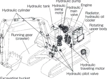
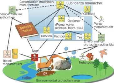
(2) Research paper : A new process to develop a hydraulic system adapted to biodegradable hydraulic oil for construction machinery (OHKAWA S. et al.). The operation manual on bio-oil for service persons and users was prepared with consideration for the EU competition law[9] (equivalent to the antimonopoly or antitrust laws of Japan). Operating conditions of construction machinery are difficult due to rocky ground, forests, and water sources in the environmental protection areas, and oil leakages are likely to occur during maintenance work in poor conditions and the backwoods. The users had to determine the use or non-use of bio-oil according to the instruction of the environmental protection authorities, and selection of bio-oil, operation, and maintenance would be conducted based on the operation manual and guidance of service persons.. the synthetic ester bio-oil shows lower viscosity increase against pressure rise (high-pressure viscosity[12]) compared to petroleum base oil.[13][14] Therefore, its oil film is thinner, and there is a disadvantage of causing seizure in the bearing metal of hydraulic motors and hydraulic pumps. Anti-seize agents such as ZDTP that compensate the thin oil film cannot be added due to the aforementioned reason. From such reasons, the commercial bio-oil has various issues such as low oxidation stability, rubber compatibility, a thin oil film and so on.[3][15][16][17] Failures are predicted if bio-oil is used without any measures taken to construction machinery that has complex hydraulic systems.. For bio-oil, rapeseed oil (glycerol fatty acid ester) and synthetic polyol esters (hereinafter, synthetic esters) are used as main ingredients (base oil). The base oil is decomposed by enzymatic reaction by microorganisms and is taken in as a nutrient (biological constituents) of microorganism (this process is called assimilation).[10] Rapeseed oil and some synthetic esters containing unsaturated fatty acids have low oxidation stability due to the presence of double bonds. Even commercial bio-oil that adopts synthetic esters of saturated fatty acids with high oxidation stability as base oil, the oxidation stability is lower compared to petroleum hydraulic oil. This is due to prohibition of additives by stringent environmental regulations,[1] and antioxidants of hindered phenol and aromatic amines that are generally used in petroleum hydraulic oil, or antioxidants and anti-seize agents of zinc dialkyldithiophosphate (ZDTP)[1] cannot be used from the perspective of aquatic environmental toxicity.[11] That is, the premise is that there is absolutely no oil leakage for petroleum hydraulic oil, while bio-oil is developed with the assumption that it may leak into the natural environmental such as rivers and marshes.. To develop a hydraulic system to which all bio-oils can be applied, the use of component analysis methods such as fishbone diagrams, fault tree analysis (FTA),[18] failure mode and effect analysis (FMEA)[19] were considered. Based on these analyses, we set out to develop equipment of the hydraulic system (hereinafter, subsystems) that comprises construction machinery that are compatible to bio-oil. FTA is a method for analyzing causes and conditions under which a phenomenon occurs by extracting the causes and factors of the established top events,[18] while FMEA is a method for clarifying the potential failure mode of system performance and its cause and effect. [19] These component analysis methods have been widely used by the automobile and construction machinery manufacturers since around 1980. In general, FTA is used to analyze the cause of failures, while FMEA is used to prevent failures during designing.. Depending on the type of synthetic ester base oil, some of Construction machinery manufacturer. Lubricants researcher Purchase. Competition law authorities. Designer (Pump, valve, cylinder, body, etc.). tion Opera al manu. Service Factory. Parts manufacturer. Test Environmental protection authorities. User Bio-oil manufacturer. Neighbors. Oil Environmental protection area. Fig. 2 Schematic diagram of stakeholders and environment in which construction machinery is used in Europe (solid line: direct relationship, dashed line: information gathering). 2 Scenario for development of construction machinery compatible with bio-oil The development scenario of this study is shown in Fig. 3. There are several issues in terms of the quality of biooil. In the development of the operation manual as a shortterm measure, directions for usage of bio-oil in construction machinery for each quality issue were determined, and brands of commercial bio-oil were categorized by quality. The short-term measures were terminated at the point when long-term measures were completed. The subjects of the long-term measures were mostly technologies of the hydraulic system of construction machinery. In relation to the production of construction machinery, there was a problem that bio-oil may mix with hydraulic oil added at the factory. For these issues, the factors of failures caused by bio-oil were analyzed by conventional FTA or FMEA to investigate and derive counter measures. However, for failures that involve chemical properties (oxidation stability) of the bio-oil, in addition to the complexity of the hydraulic system comprised of multiple subsystems, the cause investigation was difficult using the conventional methods. Also, there was no appropriate method for creating and validating countermeasures for a failure. Therefore, in this paper, we attempted the analysis of this unsolved. − 57 −. Synthesiology - English edition Vol.12 No.2 (2021).
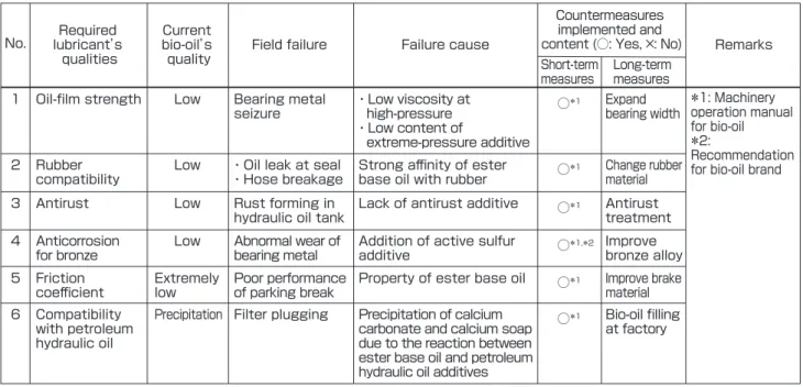
(3) Research paper : A new process to develop a hydraulic system adapted to biodegradable hydraulic oil for construction machinery (OHKAWA S. et al.). Table 1. Problems in quality of bio-oil, and short-term and long-term measures implemented by the construction machinery manufacturers using component analysis method Countermeasures implemented and content (○: Yes, ×: No). Required lubricant’ s qualities. Current bio-oil’ s quality. 1. Oil-film strength. Low. Bearing metal seizure. ・Low viscosity at high-pressure ・Low content of extreme-pressure additive. ○*1. 2. Rubber compatibility. Low. ・Oil leak at seal ・Hose breakage. Strong affinity of ester base oil with rubber. ○*1. 3. Antirust. Low. Rust forming in hydraulic oil tank. Lack of antirust additive. ○*1. 4. Anticorrosion for bronze. Low. Abnormal wear of bearing metal. Addition of active sulfur additive. ○*1,*2 Improve bronze alloy. 5. Friction coefficient. Extremely low. 6. Compatibility with petroleum hydraulic oil. Precipitation Filter plugging. No.. Field failure. Failure cause. Short-term measures. Poor performance Property of ester base oil of parking break Precipitation of calcium carbonate and calcium soap due to the reaction between ester base oil and petroleum hydraulic oil additives. problem and the derivation of countermeasures from the perspective of systems engineering[21] of a multidisciplinary approach using the System Modeling Language (hereinafter, SysML), [20] which is a graphical modeling language that supports analysis, specification setting, design, verification and validation of a complex system.. Table 1 is a summary of the problems No. 1–6 on bio-oil quality, the short-term measures and the long-term measures. Bio-oil quality. Component technology. Limit oil pressure and oil temperature. Low oil-film strength. Hydraulic pump Hydraulic motor. Recommend brand. Corrosiveness against bronze. Hydraulic hose. Limit oil temperature. Rubber swelling property. Hydraulic cylinder. Add antirust agent. Low antirust property. Hydraulic tank. Caution plate. Friction coefficient too low. Parking brake for hydraulic motor. Oil change procedure. No compatibility with petroleum hydraulic oil. Recommend brand, limit oil change interval. Low oxidation stability. Antirust treatment. ○*1. Improve brake material. ○*1. Bio-oil filling at factory. Hydraulic Production related system (long-term measure). Resolution (long-term measure). Goal of long-term measure. (Component analysis method). Failure analysis by FTA/FMEA and derivation of countermeasures. (Component analysis method). (Holistic analysis method) Investigation of countermeasures using SafeML (extended profile of SysML) description. Hydraulic oil filled at factory. Effect on whole hydraulic system. Estimation of failure mechanism using SysML description. Fig. 3 Scenario for development of construction machinery compatible with bio-oil. − 58 −. Synthesiology - English edition Vol.12 No.2 (2021). *1: Machinery Expand bearing width operation manual for bio-oil *2: Recommendation Change rubber for bio-oil brand material. to develop subsystems compatible to bio-oil. The operation manual was prepared using the component analysis method based on a survey[17][22] of bio-oil quality through chemical analysis and laboratory tests and also investigation results of field failure. Prohibition of use of low-quality bio-oil brands was considered as an short-term measure, but this was not done because it may have led to local bio-oil companies suing the authorities for violation of competition laws. Therefore, as shown in Table 2, the operation manual outlined limitations of oil temperature and pressure during operation, shortening of oil change interval, and recommended brands for each quality level, and it was left up to the users to make the selections.[17] Since the users have come to select brands with. 3 Failure analysis and countermeasures using component analyses (FTA and FMEA) for each subsystem of hydraulic system. Short-term measure (Manual). Remarks. Long-term measures. Development of construction machinery compatible with bio-oil.
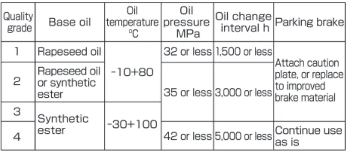
(4) Research paper : A new process to develop a hydraulic system adapted to biodegradable hydraulic oil for construction machinery (OHKAWA S. et al.). Table 2. Bio-oil classification and recommended operating condition[17] Oil Oil Oil change Parking brake temperature pressure interval h ºC MPa. Quality grade. Base oil. 1. Rapeseed oil. 2. Rapeseed oil or synthetic ester. 3 4. Synthetic ester. 32 or less 1,500 or less -10+80. -30+100. Attach caution plate, or replace to improved 35 or less 3,000 or less brake material 42 or less 5,000 or less. Continue use as is. Table 3. Cause of bio-oil oxidation and short-term measures Possible field failures. Causes of failure occurrence. Discoloration of oil. ・Unsaturated ester base oil ・Lack of anti-oxidant. Lead dissolving Corrosion and dissolution from bronze of lead by oxidation product bearing. Short-term measure Shortening of oil change interval in Table 2. quality grade 3 based on the recommendations, the operation manual was effective. For the development of subsystems that allow the use of biooil, the long-term measures were planned and conducted using the component analysis method as shown in Table 1. For problem No. 1, low oil-film strength, we conducted design change of expanding the width (surface area) of bearing metal to eliminate complex verifications. For No. 2, rubber compatibility with bio-oil, it was found that the strengths of nitrile rubber (NBR) with low nitrile content and chloroprene rubber (CR) decrease significantly.[16] Therefore, these rubber parts were replaced to materials of hydrogenated NBR (HNBR) or NBR with high nitrile content for high oil resistance. For No. 3, poor antirust property of bio-oil, an antirust coating was applied inside the hydraulic oil tank. For No. 4, corrosion of bronze, an improved bearing material, which has anticorrosive property against hydrogen sulfide, was developed maintaining the bearing property by adding zinc to the metal composition.[23] For No. 5, excessive low torque of multi-disk wet parking brakes, a new brake material was developed and was adopted for producing high torque in bio-oil in collaboration with a brake material manufacturer. For No. 6, filter plugging caused by a chemical reaction between bio-oil and petroleum hydraulic oil additives, we took measures to prevent mixing with petroleum hydraulic oil by shipping the machinery with factory filled bio-oil to users who requested bio-oil. For t he low ox id at ion st abilit y of bio - oil, on ly t he discoloration (darkening) of the rapeseed oil was the failure encountered in the field, as seen in Table 3. Although the possibility of lead dissolving from the lead bronze bearing was considered, there were no failures in the market.. Therefore, the authors determined that there was no problem other than instructing the proper oil change interval to the users. As a long-term measure, a new bio-oil with high oxidation stability with the goal of achieving quality grade 4 could be developed,[15][17] but it was unable to clear the European environmental toxicity regulation[8] and was not introduced to the European market. The following problem occurred after the aforementioned series of countermeasures. In construction machinery operated in the field, malfunctions of hydraulic valves caused by bio-oil occurred, and lack of pressure in the hydraulic pumps and malfunctions of hydraulic cylinders and hydraulic motors became problems. From the surveys of these matters, the cause was suspected to be abnormal wear and sticking of the hydraulic valves due to wear debris produced inside and sand dust that entered from outside (hereinafter, oil dust), but the direct relationship to bio-oil was unclear. It was thought that because of low oxidation stability of bio-oil, oil-insoluble oxidative polycondensation products[1] (hereinafter, lacquer) were formed, which then adhered to the hydraulic valve to cause malfunctions. However, there was no lacquer adhesion upon inspection of the malfunctioned hydraulic valve. It seemed that the malfunction phenomenon subsided, but the cause of hydraulic valve malfunction was never clarified. Due to this fact, we were unable to complete the development of the construction machinery that was compatible with bio-oil.. 4 Application of holistic analysis method using system model for cause investigation and countermeasure for the whole system As described earlier, it was necessary to newly conduct a holistic analysis using a system model described by SysML for the failures involving oxidation stability of bio-oil, in addition to the complex hydraulic system. Since SysML was a modeling language that enabled graphic description of system requirements, structure, and behaviors, and supported verification and validation, we thought it would be effective to combine system models described by SysML and SafeML (extended profile of SysML, details will be explained later) for cause investigation and countermeasures, as shown in Table 4. It is difficult to apply the conventional component analysis method to the analysis of the whole system in cases in which the cause is particularly complex, and the mechanism cannot be graphically rendered. The component analysis method has the disadvantage that the descriptive technical terms cannot be understood or reviewed unless one is an expert. In contrast, SysML allows description even if the cause is complex, and simple descriptions can be used for technical terms (for example, a “hydraulic valve” is described as “a subsystem to control the f low of oil”), and it can be easily understood in graphical form even by multidisciplinary team members. Although SysML allows validation of a countermeasure, it cannot create or verify. − 59 −. Synthesiology - English edition Vol.12 No.2 (2021).
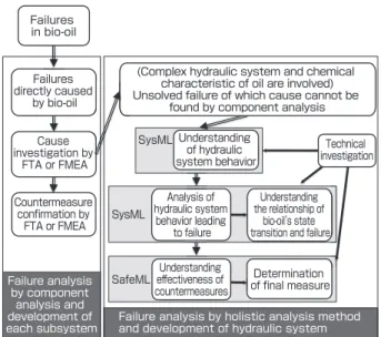
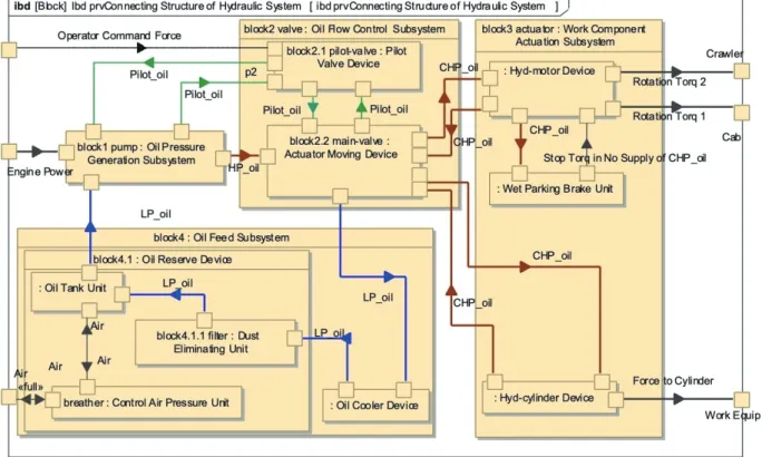
(5) Research paper : A new process to develop a hydraulic system adapted to biodegradable hydraulic oil for construction machinery (OHKAWA S. et al.). Table 4. Comparison of previous methods of analyses and countermeasure and a new holistic method using system model (○: Possible, : Partially possible, ×: Impossible). Cause investigation Countermeasures Previous methods Case study of Application to Visualization of Multidiscipline No. or modeling Resolution cause investigation complex systems failure mechanism Verification Validation discussion language planning for failures and causes (behavior) 1 Fishbone diagram 2 FTA 3 FMEA SysML 4 SysML SafeML 5. Yes Yes Yes No Yes. × × × ○ ×. × × × ○ △. the countermeasure. SafeML is a language that defines the combination of hazards, hazardous context, and harm as risks and can clearly describe defense (countermeasure) methods. However, SafeML cannot illustrate in detail the failure mechanism. SysML and SafeML allows multidisciplinary investigation by a team even with some people who are not engineers. Figure 4 shows the integrated methods of both analysis and development on the hydraulic subsystem and system against bio-oil using the conventional component analysis method and the holistic analysis method. W hile the component analysis is effective for cause investigation and countermeasure planning focusing on individual subsystems, it cannot handle complex problems like a malfunction of a hydraulic valve that needs to be solved observing the state of bio-oil, while looking at the whole hydraulic system. In this paper, the action of the hydraulic system is described and understood as a systems model using SysML. Next, the mechanism of a hydraulic system that leads to failure (hereinafter, behavior) is described, the relationship with the bio-oil state transitions is grasped, and the cause is assumed. Failures in bio-oil. Failures directly caused by bio-oil Cause investigation by FTA or FMEA Countermeasure confirmation by FTA or FMEA. Failure analysis by component analysis and development of each subsystem. (Complex hydraulic system and chemical characteristic of oil are involved) Unsolved failure of which cause cannot be found by component analysis SysML Understanding of hydraulic system behavior. Technical investigation. Analysis of hydraulic system behavior leading to failure. Understanding the relationship of bio-oil’ s state transition and failure. Understanding SafeML effectiveness of countermeasures. Determination of final measure. SysML. Failure analysis by holistic analysis method and development of hydraulic system. Fig. 4 Development of each subsystem against bio-oil, and development method of hydraulic system using system model described by SysML. × × × × ○. × ○ ○ ○ ○. × × × ○ ○. Also, the relationship with failure is understood from the biooil state transitions. Although there are several attempts to integrate SysML with safety analysis,[24]–[27] SafeML proposed by Biggs et al.[27] is the most practical. SafeML is an extended profile of SysML specific to safety information, and can clearly describe system risks, countermeasures taken for the risks, and risk management results.[28] Using this SafeML, the countermeasures are created for the situation in which a failure occurs, and the effect of such countermeasures, validation, and also countermeasure costs are considered. The safety score (will be explained later) is calculated according to the items pertaining to the safety of system behavior that is clarified here. In this system model, descriptions are written at the parts level of the hydraulic system, to allow easy understanding by the parts manufacturers of the subsystem.. 5 Understanding of hydraulic system by holistic analysis method using system model and result of technical investigation of failure factor 5.1 System model description using SysML Behavior of the whole construction machinery is shown in the activity diagram of Fig. 5. The activity diagram shows behavior using input flow, output flow, control flow (dashed line), object flow (solid line), and action blocks.[20] The “Engine” drives the “Hydraulic System” by output of “Generate Power” action. The operator controls the hydraulic system by “operator command force” f low, and transfers hydraulic pressure into force or rotational torque to the “Work Component” partition by the “Provide Hydraulic Force” action. The work components are set in motion to perform actions such as “Excavate Earth,” “Rotate Excavating Direction,” or “Run Machinery.” To adjust air pressure of the hydraulic system, a small amount of “Air” is taken in a “discrete” manner. Similarly, the context of the hydraulic system is shown in the internal block diagram of Fig. 6. The hydraulic pump “block1 pump: Oil Press Generation Subsystem” is driven by the “Engine Power,” and high-pressure (35 MPa) oil “HP_oil” and middle-pressure (3 MPa) pilot oil “Pilot_. − 60 −. Synthesiology - English edition Vol.12 No.2 (2021). × × × ○ △.
(6) Research paper : A new process to develop a hydraulic system adapted to biodegradable hydraulic oil for construction machinery (OHKAWA S. et al.). oil” are produced. The operator adjusts the pressure of the hydraulic pump and controls the main valve “block2.2 mainvalve: Actuator Moving Device,” through the pilot valve “block2.1 pilot valve: Pilot Valve Device” in the hydraulic valve “block2 valve: Oil Flow Control Subsystem.” The main valve is composed of multiple units that control the f low direction, flow rate, and oil pressure of the high-pressure oil. The controlled high-pressure oil “CHP_oil” actuates the hydraulic motor device and hydraulic cylinder device in the subsystem that moves the work component “block3. actuator: Work Component Actuation Subsystem.” The highpressure oil after the actuation returns to the main valve and becomes low-pressure (0.1 MPa) oil “LP_oil,” and enters the oil feed subsystem “block4: Oil Feed Subsystem.” Since the oil temperature increases due to heat release as high-pressure oil becomes low-pressure oil, as well as due to friction of various parts and heat generation by viscous resistance, oil cooling is provided by “Oil Cooler Device.” Oil dust in the low-pressure oil is eliminated by the filter “block4.1.1 filter: Dust Eliminating Unit” and returns to the “Oil Tank Unit.”. Fig. 5 Activity diagram of construction machinery domain. Fig. 6 Internal block diagram of hydraulic system of construction machinery. − 61 −. Synthesiology - English edition Vol.12 No.2 (2021).
(7) Research paper : A new process to develop a hydraulic system adapted to biodegradable hydraulic oil for construction machinery (OHKAWA S. et al.). 5.2 Technological investigation on failure factor 5.2.1 Consideration of subsystem (pump and valve) that causes oxidation of bio-oil There was no long-ter m counter measure for the poor oxidation stability of the bio-oil, and it was thought that the oxidation stability had something to do with hydraulic valve malfunctions. Therefore, to understand the cause of hydraulic system malfunctions, it was necessary to clarify in which subsystem the bio-oil underwent oxidation. In Fig. 6, the subsystem in which oxidation is most likely to occur is the hydraulic pump with high load and temperature, but no investigation has been done on the possibility of oxidation in the hydraulic motor, the hydraulic cylinder in “block3 actuator” and in the main valve “block2.2 main-valve.” Kazama et al.[29] conducted temperature measurement of the swash-plate-type axial piston hydraulic pump (21 MPa) used in construction machinery, and observed a temperature increase of 30 ºC or higher at the cylinder block (increase to 110 ºC when oil temperature was 80 ºC). In cases in which there were bubbles in the oil, hot spots of 1,400 ºC or higher (in cases of 35 MPa) were produced due to adiabatic compression, and the surrounding bio-oil became heated.[30] It could be assumed that the bio-oil underwent oxidation to become lacquer. The energy loss of all subsystems during the operation of construction machinery may reach 60–75 %,[31][32] and according to the authors’ study, it was about 15 % at the hydraulic pump, and about 25 % at the main valve. Since energy loss leads to increased oil temperature, it can be assumed that the oil temperature inside the main valve becomes higher than the hydraulic pump. There is a relief valve that releases high-pressure oil into a low-pressure circuit in the main valve. When the motion of the hydraulic cylinder or the hydraulic motor is stopped when there is excessive load on the hydraulic system, as when construction machinery is removing a large rock with an excavating bucket, excess high-pressure oil is released into the LP_oil circuit of the Oil Feed Subsystem from the relief valve in “block2.2 main-valve,” and the kinetic energy is converted to heat. When the heat value at the relief valve is calculated according to Equation (1),[33] the oil temperature reaches about 100 ºC (from oil temperature 80 ºC), and this is equivalent to the oil temperature of the hydraulic pump. H=p•Q. actuator.” The oil flows at flow rate 100 m/s or more at the unit that controls the flow direction of high-pressure oil,[1] and severe cavitation occurs. This may cause damage to the quenched or carburized steel parts.[1] In such severe cavitation, high-temperature and high-pressure (about 4,700 ºC and 100 MPa) hot spots[35] may occur due to the collapse of bubbles. In this situation, molecules may be broken down almost to the atom level or carbon bonds may be randomly split.[35]–[37] It is assumed that this causes surrounding bio-oil to become oxidized and lacquer is formed. Also, damage by cavitation may occur inside the hydraulic pump although at a smaller scale.[38] From these investigations, the authors found that lacquer was formed in the hydraulic pump and at the hydraulic valve. Although lacquer formation may occur in the hydraulic cylinder and the hydraulic motor, the load factor is lower compared to the hydraulic pump or the main valve. In the past, problems were caused by cavitation during rotation switching from left to right in the hydraulic swing motor, but currently countermeasures are taken by improving the hydraulic valve.[31] Therefore, it is assumed that lacquer for mation is minimal in the hydraulic motor and the hydraulic cylinder. The formed lacquer does not dissolve in bio-oil, is captured in the filter, and may cause plugging. 5.2.2 Consideration of oil dust and filter Figure 7 shows the structure of the hydraulic tank, filter, and breather “block-4.1” in Fig. 6. The filter “block-4.1.1 filter” captures oil dust during by passing of low-pressure oil about 20–100 times. According to our experiments conducted by the authors using actual machinery, conventional cellulose filters (explained later) can capture 50 % or more oil dust of 5 μm or more in a few hours. The number of particles of oil dust (cleanliness level) can be kept below the upper limit required for the hydraulic system. It is designed so that when the filter is plugged and pressure increases, the filter bypass Breather Filter. Filter inside breather Air/dust. Low-pressure oil. (1) Filter bypass valve. Here, H is the heat value (KJ/min) from the relief valve, p is relief pressure (MPa), and Q is relief flow rate (L/min). Imanishi et al.[34] conducted simulations of the action of the main valve “block2.2 main-valve,” and showed that the energy loss is large, equivalent to the relief valve unit, even at the unit that controls the direction of the flow of highpressure oil from the main valve to the actuator “block3. Hydraulic tank. Pipe to hydraulic pump. Fig. 7 Schematic diagram of hydraulic tank and filter/ breather. − 62 −. Synthesiology - English edition Vol.12 No.2 (2021).
(8) Research paper : A new process to develop a hydraulic system adapted to biodegradable hydraulic oil for construction machinery (OHKAWA S. et al.). Table 5. Limit value of particle count (cleanliness level) for each particle diameter of oil dust, and typical particle count values in hydraulic oil where failure occurred Particle size µm. 5-15. 15-25. 25-50. 50-100. >100. Upper limit of particle numbers mL-1. 500,000. 32,000. 4,000. 1,000. 100. 96,990. 3,120. 140. 0. Examples of contamination where 3,490,150 failure occurred mL-1. valve opens, and the low-pressure oil does not go through the filter and enters the hydraulic tank directly. The timing of filter replacement is set at 250–500 h, and this is calculated from the volume of oil dust captured. As mentioned before, oil dust is composed of outside dust and metal wear debris from the interior. The outside dust enters as dust particles and muddy water along with air intake, from the filtered breather [39] in “block4.1” that is installed in the hydraulic tank. Since the air goes through the breather filter only once, fi ne dust cannot be prevented and this becomes the source of oil dust. This filter is made of a cellulose material the same as the oil filter. The outside dust may enter during oil feeding, filter exchange, hydraulic hose exchange, and subsystem repair at sites with poor conditions. Therefore, oil dust contains hard components (Vickers hardness HV 600 or more) such as oxidized iron and steel that are metal wear debris, as well as silica sand (quartz) or feldspar from dust. Table 5 shows the cleanliness limit values[1] for oil dust that were prepared by the authors,[40] and also provides examples of typical cleanliness levels at which. failures occurred. When limits are exceeded, malfunction due to abnormal wear or sticking of the hydraulic valve may occur.[33] Since the gap of the movable parts such as the main valve and the pilot valve is about several μm to 30 μm,[1] oil dust may enter the gaps even if it is within the cleanliness limit. In the case of a field pump failure, the number of oil dust reached at maximum seven times the cleanliness limit.. 6 Investigation result of hydraulic system behavior leading to failure 6.1 Normal behavior of bio-oil in hydraulic system Figure 8 shows the activity diagram of the normal behavior of the hydraulic system. The activity partitions in this figure match the subsystem blocks in Fig. 6. The hydraulic pump “block1 pump” sends high-pressure oil “HP_oil” to the hydraulic valve “block2 valve.” The operator controls the hydraulic valve to adjust the pump pressure by pilot oil and controls the direction and flow rate of the high-pressure oil. This controlled high-pressure oil “CHP_oil” moves the actuator “block3 actuator” such as the hydraulic motor and the hydraulic cylinder. This moves the “Work Component.” The high-pressure oil used in the work returns to the oil feed subsystem “block4” as low-pressure oil “LP_oil” through the hydraulic main valve, becomes cooled as “Cool LP_Oil,” filtered as “Filtrate LP_oil,” goes to the oil tank “Reserve LP_Oil” as clean low-pressure oil “clean LP_oil,” and enters the hydraulic pump to become pressurized gain. However, when the viscosity of the bio-oil is high such as during lowtemperature start-up, the filter differential pressure becomes high “filtration pressure => 0.15 MPa,” and the bypass valve in the filter temporarily opens. Then, the bio-oil will not pass. Fig. 8 Activity diagram of normal state of hydraulic system. − 63 −. Synthesiology - English edition Vol.12 No.2 (2021).
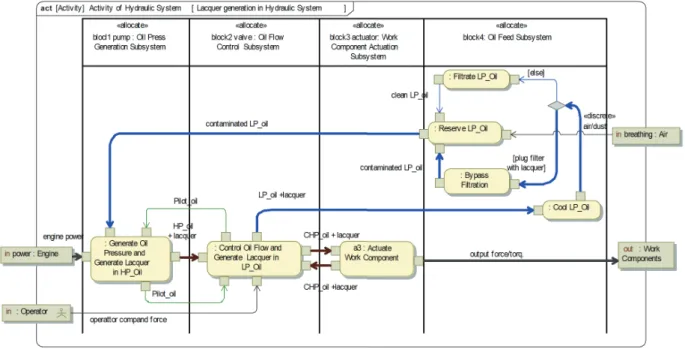
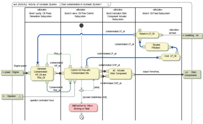
(9) Research paper : A new process to develop a hydraulic system adapted to biodegradable hydraulic oil for construction machinery (OHKAWA S. et al.). through the filter “Bypass Filtration,” and enters the oil tank while containing oil dust “contaminated LP_oil.” The oil temperature increases to 60 ºC or more in about 30 min after start-up, the low-pressure oil will start passing through the filter, and the amount of oil dust decreases immediately. 6.2 Investigation result of behavior of hydraulic system malfunction by bio-oil oxidation The activity diagram of Fig. 9 shows the formation of lacquer by oxidation of bio-oil and its behavior in the hydraulic system. (1) In the hydraulic pump with increased oil temperature, lacquer forms in the high-pressure oil due to adiabatic compression of bubbles “Generate Oil Pressure and Generate Lacquer in HP_oil.” The high-pressure oil containing lacquer “HP_oil + lacquer” f lows into the hydraulic valve. (2) Severe cavitation occurs at the hydraulic valve, lacquer is formed in low-pressure oil “Control Oil Flow and Generate Lacquer in LP_Oil,” and this flows into the oil feed subsystem. (3) The high-pressure oil containing lacquer flows into the actuator, but the effect on the actuator may be small. (4) The lacquer is captured in the filter “Filtrate LP_oil” of the oil feed subsystem, and clean low-pressure oil returns to the hydraulic pump. However, as the lacquer gradually accumulates in the filter, the filter differential pressure becomes 0.15 MPa even at oil temperature of 60ºC or more, and the filter bypass valve remains open and the filter is plugged “plug filter with lacquer.” As a result, oil dust and lacquer are not filtered and mix into the lowpressure oil as “contaminate LP_oil,” and the low-pressure oil contaminated with oil dust flows. The behavior of the contaminated bio-oil in the hydraulic system is shown in Fig. 10. The contaminated low-pressure oil is sucked into the hydraulic pump and becomes high-. pressure oil and pilot oil containing oil dust and lacquer “Generate Contaminated HP_Oil and Pilot_Oil,” and these are sent to the hydraulic valve. The wear debris concentrates in the contaminated high-pressure oil “contaminated HP_ oil” at the actuator, the oil returns to the oil feed subsystem as low-pressure oil. In the “Reserve LP_Oil,” outside dust “ air/dust” is entered and is concentrated. This is repeated and when the concentration of oil dust surpasses the upper limit of cleanliness “exceed cleanliness limit” ( below ●), malfunction occurs “Malfunction by Valve Sticking or Wear” by sticking or abnormal wear as the oil dust enters the gap of the hydraulic valve, including both the main valve and the pilot valve. The flow ends ( ) and repair becomes necessary. It was found that the hydraulic valve malfunction causes faulty or no movement of the hydraulic pump, the hydraulic motor, or the hydraulic cylinder.. 7 Investigation result of relationship between bio-oil state transition and failure 7.1 System model description of bio-oil state transition Figure 11 is a state machine diagram that shows the behavior of state transition pertaining to bio-oil oxidation and dust inclusion. When oxygen is dissolved in bio-oil, part of the bio-oil becomes radicals due to oxidation even at oil temperature of around 100 ºC.[41] Radicals are short-lived molecules that are activated by the break in parts of the bond in oil molecules,[42] and tend to accelerate oxidation in a chain reaction. The radicals of bio-oil cause oxidation by a reaction mechanism similar to petroleum hydraulic oil.[43] The authors have confirmed in oxidation stability tests[44] that lacquer begins to form when bio-oil was oxidized. Fig. 9 Activity diagram for lacquer formation and its behavior of bio-oil in hydraulic system. − 64 −. Synthesiology - English edition Vol.12 No.2 (2021).
(10) Research paper : A new process to develop a hydraulic system adapted to biodegradable hydraulic oil for construction machinery (OHKAWA S. et al.). in conditions of 135 ºC × 500 h or more.[15][22] No lacquer formation was observed in this condition for petroleum hydraulic oil. The maximum oil temperature of the hydraulic system for construction machinery is low at 110 ºC,[1] and will not reach 135 ºC. Therefore, the authors assumed that rapid radical formation, oxidation, and lacquer formation occurred. in bio-oil only after emergence of local high-temperature regions, or hot spots, due to adiabatic compression of bubbles[30] and cavitation [35] as mentioned earlier. Bio-oil containing lacquer is in a deteriorating state. If lacquer is removed by a filter, it is considered as a “Normal” condition. Lacquer is removed up to the upper limit of the filter capacity. Fig. 10 Activity diagram of contaminated bio-oil and malfunction occurrence of hydraulic system. Fig. 11 State machine diagram showing state transition of bio-oil. − 65 −. Synthesiology - English edition Vol.12 No.2 (2021).
(11) Research paper : A new process to develop a hydraulic system adapted to biodegradable hydraulic oil for construction machinery (OHKAWA S. et al.). “lacquer elimination possible.” When lacquer accumulates in the filter and the filter differential pressure increases, the filter becomes plugged as “filter plugged with lacquer” in Fig. 9, and the bio-oil is contaminated with oil dust and lacquer. Ultimately, it can be derived that contamination by oil dust means to exceed the limit of cleanliness of the hydraulic system, even in the study described by the state machine diagram. Oxidation products, [45] that are produced by oxidation reaction, and radicals dissolve in oil, move past the filter, and circulate the hydraulic system. High-reactive radicals have short lifespans (1 ns to several hours), while low-reactive radicals have lifespans of a year or more.[46][47] It is thought that not too many highly reactive radicals that may produce lacquer accumulate in oil. However, oxidation products become concentrated. 7.2 Technological investigation result of bio-oil state transition 7.2.1 Acid value increase in bio-oil field test To study the effect of concentration of oxidation products of bio-oil on lacquer formation, we conducted a field test of construction machinery for commercial bio-oil with base oil of saturated fatty acid synthetic ester that has higher oxidation stability.[48] The result is shown as the solid line of Fig. 12. The acid value of bio-oil, which is the index for oxidation product concentration, approaches the use limit of petroleum hydraulic oil when it exceeds 3,000 h. The acid value is the index of the acidic component or the amount of free fatty acids in the lubricating oil, and it is expressed by the amount of potassium hydroxide needed for neutralization. When this limit is exceeded, the oxidation product corrodes and dissolves the lead in the bronze bearing metal, and seizure occurs.[49] Therefore, the authors set a standard that the recommended oil change interval of saturated fatty acid 3.5. Upper limit of petroleum hydraulic oil. It is said that in synthetic ester bio-oil, hydrolysis occurs with a mixture of a few percent of water and the acid value increases. [50] However Totten et al. [38] determined that hydrolysis does not occur since water entering the hydraulic excavator is 0.1 % or less. The authors similarly obtained results that hydrolysis did not occur in the field tests,[48] and therefore, only the state transition of oxidation is shown in Fig. 10. 7.2.2 Investigation of filter plugging in cases other than bio-oil To investigate the mechanism of lacquer formation, the authors studied lacquer formation in petroleum hydraulic oil and engine oil. In the field tests of extending the filter change interval from 500 h to 5,000 h in large construction machinery, which was a wheel loader using petroleum hydraulic oil, significant lacquer adhesion on the filter was observed (Fig. 13). Brown lacquer adhered to the white endplate and the yellow cellulose filter material and the filter material was plugged with lacquer. Since petroleum hydraulic oil has low acid value even at 4,000 h (Fig. 12), it is thought that the increased acid value was not related to lacquer formation, but the filter was plugged by lacquer formation near the hot spots. The authors also clarified the cause of similar failure in engines.[51] Radicals are formed in the engine oil due to nitrogen oxides (NOx) in the combustion gas, and a large amount of lacquer is formed, and excessive wear of engine parts occurs due to early filter plugging. The engine oil used in this study did not contain effective antioxidants against. 2.5. Saturated synthetic ester. 2.0. End plate. 1.5 1.0. Petroleum hydraulic oil. 0.5 0.0. 0. 1000. 2000. 3000. 4000. Filter element. Acid value (mg KOH/g). 3.0. synthetic ester bio-oil should be every 3,000 h (Table 2) for standard European products, to maintain the acid value below the limit value. Regarding petroleum hydraulic oil, since rapid acid value increase does not occur as shown in the dashed line in the figure, the oil change interval is set at every 5,000 h. In the next section, we consider whether the increased oxidation in bio-oil is related to lacquer formation.. Operating hour (h). Logo mark, product number. 100 mm. Fig. 12 Acid value change of bio-oil of saturated fatty acid synthetic ester base oil [48] and that of petroleum hydraulic oil during field test of construction machinery,. Fig. 13 Lacquer adhered on filter element in extension test (4,200 h) for filter change interval. − 66 −. Synthesiology - English edition Vol.12 No.2 (2021). Reinforced cloth band.
(12) Research paper : A new process to develop a hydraulic system adapted to biodegradable hydraulic oil for construction machinery (OHKAWA S. et al.). NOx oxidation. It is the same situation as bio-oil that does not contain effective antioxidants against radicals. Such filter plugging by lacquer formation backs the assumption of the behavior in the state transition of bio-oil.. 8 Proposal of countermeasures for malfunction using extended SafeML 8.1 Extension of SafeML Hazardous situations were described using SafeML based on the behavior of malfunctions described by SysML, and countermeasures were investigated. However, conventional SafeML did not target hazard sources of failure of a product itself. [28] Therefore, the authors extended the language by adding “Short-term defence,” “Long-term defence” (hereinafter, countermeasure), and market survey “Field Survey” to understand the effect of short-term measures that are shown in three pur ple elements as “Defence elements” of SafeML (Fig. 14). This paper will not address the short-term measures and the field survey. Biggs et al.[27] attempted calculation of the relative and quantitative “Safety Score” (see Appendix A) for multiple measures. Here, we attempt the application of the safety score for selecting the countermeasures. 8.2 Proposal for malfunction and countermeasures describing by extended SafeML Three countermeasures can be proposed as described by the extended SafeML, as shown in Fig. 15. The countermeasures against the hazardous/harmful situations are described in Figs. 8–10. The use of unacceptable bio-oil, which is easy to. deteriorate, that is inappropriate for construction machinery (pink element) is a “Hazard,” and the malfunction of the hydraulic valve due to oil dust (red element) is “Harm.” The source of the hazard is bio-oil, and it is shown in association as <<deriveHzd>>. “Harm Context” (yellow element) is the occurrence of sticking or abnormal wear of the hydraulic valve caused by oil dust as the filter is plugged prematurely due to the deterioration of the bio-oil. Since the element where the harm context occurs is in the hydraulic valve, it is shown in association as <<deriveHC>>. The longterm measures (green element <<Long-term defence>>) are proposals for preventing the harm context, and specific effects are shown in the result of long-term measures (blue element <<Defence Result>>). The five tag values are entered into the red, yellow, green, and blue elements. These include investigations of the probability of success, probability of occurrence, probability of harm, and range of harm, and severity of harm.[27] The safety requirement (light pink element <<requirement>>) that is shown in association as <<req Defence>> is described to validate long-term measures. The equipment for long-term measures associated to <<satisfy>> and the test <<test case>> associated to <<verify>> in the safety requirements can be specifically described through information sharing among the design department and the test department. The basic countermeasures considered from malfunction behaviors are as follows: to prevent occurrence of hot spots by lowering excessive high-pressure oil, to prevent oxidation of bio-oil, and to prevent filter plugging. The specific proposals for the three long-term measures are shown below.. Fig. 14 Elements added to SafeML (purple element). − 67 −. Synthesiology - English edition Vol.12 No.2 (2021).
(13) Research paper : A new process to develop a hydraulic system adapted to biodegradable hydraulic oil for construction machinery (OHKAWA S. et al.). 8.2.1 Proposal 1 The green element “(1) Auto engine controller” suppresses the release of excessive high-pressure oil from the relief valve unit of the main valve by engine control to reduce cavitation and lacquer formation. With this long-term measure proposal, a safety requirement of reducing excess oil pressure at low operating load operation (light pink element) is generated. To fulfill the requirement, it is necessary to investigate by a “Machinery Test” for the engine rotation controlling device “block, Engine Controller.” The result of the countermeasure (blue element) is the ability to reduce lacquer formation by lowering the pressure of the hydraulic valve to prevent filter plugging. 8.2.2 Proposal 2 The green element “(2) Centrifugal air bubble separator” involves the removal of air bubbles in the oil using a centrifuge, [30] and the reduction of lacquer formation by adiabatic compression at the hydraulic pump. The safety requirement is the reduction of oil oxygen content to prevent oxidation of bio-oil (light pink element). For the centrifugal air bubble separator that fulfills this safety requirement, it is necessary to conduct tests for the oil feed subsystem (yellow element). The effect of the countermeasure is to prevent bypassing of oil dust by controlling the deterioration of the bio-oil (blue element).. 8.2.3 Proposal 3 The green element “(3) Improved Filter” involves the prevention of plugging by lacquer by improving the filtration performance of the filter. The safety requirement is to prevent filter plugging (light pink element). For the improved filter that uses the newly improved filter media that can fulfill this requirement, it is necessary to conduct a “Filter Bench Test.” The result of the countermeasure is to prevent the release of oil dust by increasing the capacity of the filter (blue element). 8.3 Technological investigation of countermeasure Oil temperature decreases if pressure of high-pressure oil is reduced at low-load operation by automatic control of the engine, and release of excess high-pressure oil from the relief valve of the main valve is reduced. However, since cavitation occurs by other hydraulic valve operations, the effect is limited. For the deterioration of hydraulic oil, Sakama[30] clarified that the progress of oxidation reaction can be controlled by reducing the oxygen content in the hydraulic oil by centrifuging the air bubbles in oil. However, as mentioned before, antioxidants, which can sufficiently inhibit radical reactions, are not added to bio-oil, and it is thought that oxidation reaction occurs even in a state of reduced oxygen content. Therefore, sufficient results of oxidation prevention cannot be expected by the centrifuge method.. Fig. 15 SafeML diagram for three long-term measures for malfunction of hydraulic valve caused by bio-oil. − 68 −. Synthesiology - English edition Vol.12 No.2 (2021).
(14) Research paper : A new process to develop a hydraulic system adapted to biodegradable hydraulic oil for construction machinery (OHKAWA S. et al.). Table 6. Comparison of five items tag value, safety score, and cost evaluation of cases without countermeasures and cases with three countermeasure proposals. No.. Probability Probability of Probability of Range of Severity of Safety score Cost of defence context occurrence harm occurrence harm harm evaluation success of or or or or. Countermeasures (defence). -. High (1.0000). High (1.0000). Many (0.7500). S2 (0.5000). 0.3750. -. Automatic engine controller (economy mode). Low (0.3333). High (1.0000). High (1.0000). Some (0.5000). S2 (0.5000). 0.3333. Small (0.5000). 2. Centrifugal air bubble separator. Medium (0.6667). Medium (0.6667). High (1.0000). Few (0.2500). S2 (0.5000). 0.0741. Great (1.0000). 3. Improved filter. High (1.0000). Low (0.3333). High (1.0000). Few (0.2500). S2 (0.5000). 0.0000. Small (0.5000). 0. Undefended case. 1. Table 7. Occurrence of the malfunction in machinery before/after filter improvement Average annual occurrence of malfunction (over 2 years) Vehicles using conventional cellulose filter. 10.5. Vehicles using improved filter. Less than 1.4. For filters, improvement of filter materials has advanced recently, and the capturing performance of dust has increased and the lifespan until plugging has been extended.[52] In the measurement results of JIS hydraulic filter performance tests,[53] while a conventional cellulose filter material captures over 50 % of the dust of 20–30 μm or more, an improved filter material made by mixing glass fiber with polypropylene fiber can capture 50 % of dust of the size of 5 μm or more.[1] It is also reported that the filter lifespan using the improved filter media can be more than twice longer than the conventional material.[52] The diameter of a cellulose filter is at maximum 30 μm, while the diameter of the improved filter media is at maximum 1.0 μm. This is the reason the filter performance has improved, and it has prevented plugging of the filter by lacquer, and has enabled capture of oil dust, thus preventing sticking and abnormal wear of the hydraulic valve. 8.4 Determination of countermeasures Table 6 shows the “Safety Score” (SS) and cost evaluation calculated using the equation in Appendix A, based on the tag values in the elements of Fig. 15, for a case without cou nter measu res ( Undefended case) and cases with countermeasures. The probabilities of occurrence were categorized and quantified into three stages: low (Low: 1/3), medium (Medium: 2/3), and high (High: 1/1). The ranges of harm were set in four levels: 0.3 % or less (Few:1/4), medium level (Some: 2/4), high level (Many: 3/4), and 10 % or more (Most: 4/4). The severities of harm were set in four levels: cases that only require part replacement, cleaning, and adjustment that incur hardly any cost (S1: 1/4); cases that require replacement of parts or subsystems on site, or. require disassembly and cleaning (S2: 2/4); cases that require repair of subsystems in a repair shop (S3: 3/4); and cases that require total repair of the vehicle or in which human injury has occurred (S4: 4/4). Cost evaluation was set in 4 levels: compatible and inexpensive (Minimum: 1/4), to small (Small), medium (Medium), and cases that require addition of part numbers of new subsystems and modification of the car body (Great: 4/4). In the case of undefended case, the safety score is 0.3750, but the filter improvement plan has a safety score 0.0000 with the lowest value (highest effectiveness) and also has low cost. Therefore, we adopted the use of the improved filter. The safety score for the auto engine controller is 0.3333 and the one for the centrifugal air bubble separator is 0.0741, so the effectiveness of the countermeasures is lower than that of the improved filter. For cost evaluation, the auto engine controller was already employed in some models and its installation in all models had been decided, and the cost was evaluated as small. The centrifugal air bubble separator requires a new design of the hydraulic tank, and its installment has not been determined except in a few models,[54] and we set the cost evaluation as “great.” Since the improved filter is not compatible with the conventional filter due to the strength of the filter media, the cost was set as “small” rather than “minimum.” 8.5 Technical validation of countermeasures Recently, the authors employed a filter with improved filter media to extend oil change interval. As a result, we found that there was no occurrence of malfunction of the hydraulic valve due to bio-oil in construction machinery as shown in Table 7. The effects expected by the use of the improved filter was to extend the oil change interval of petroleum hydraulic oil that had high oxidation stability and sufficient oil lifespan, by capturing and removing as much oil dust as possible. The auto engine controller was already used in some machinery that also used the conventional cellulose filter, but it was assumed that there was hardly any effect on malfunction. The centrifugal air bubble separator for. − 69 −. Synthesiology - English edition Vol.12 No.2 (2021).
(15) Research paper : A new process to develop a hydraulic system adapted to biodegradable hydraulic oil for construction machinery (OHKAWA S. et al.). hydraulic oil was adopted in some machinery[54] as mentioned earlier, but the effect on bio-oil has not been observed. From these results of confirmation, it was shown that the determination of countermeasures using the safety score was appropriate.. 9 Discussion. biodegradable hydraulic oil in construction machinery as promoted in Europe, utilizing a holistic analysis method using system models. As a result, through the activities of the project team for bio-oil using the component analysis method, the following countermeasures were implemented.. The project team was able to quickly implement short-term and long-term measures because component analysis methods had been deeply rooted in the construction machinery ma nufact u rers. Wit h t he ser ies of cou nter measu res (short-term and long-term measures), a certain degree of recognition was gained from the users and service persons, but the unsolved malfunctions of the hydraulic valve caused discontent among the users and service persons.. 1) As a short-term measure, a manual of bio-oil was created within half a year. This was distributed to the users through service personnel. This manual was effective until the completion of the long-term measures.. By analyzing the unsolved failures and proposing measures through an holistic analysis method using the system model described by SysML, we were able to complete the development of the hydraulic system of the construction machinery that allowed use of bio-oil. It was found that we were able to describe the cause and mechanism of the malfunctions based on the description in SysML, and we were able to determine the countermeasures based on the description in SafeML. Through this analysis, while only lead dissolution in bearing metal and oil discoloration were conventionally thought to be the problems caused by the low oxidation stability of bio-oil, it was newly clarified that filter plugging occurred by lacquer formation in the hydraulic oil. It was found that the filter not only captured oil dust, but also had the function of preventing oxidation and deterioration of oil by capturing lacquer produced by oxidation. In the future, development looking at the whole system using this new integrated analysis method will be possible. SafeML can graphically describe hazardous situations, countermeasures (defences), and safety requirements for failures, and these can be reviewed by a multidisciplinary team including those who are not engineers. The selection of countermeasures becomes possible from easy-to-understand indices of safety scores and cost. While the component analysis method has the disadvantage against problems that cover the whole complex system, it is an effective method for the analysis of failures in subsystems or parts as it can be done in a short time. The holistic analysis method using system models by SysML description has the disadvantage that it may take time to gain proficiency. Therefore, as shown in Fig. 4, it is recommended that the component analysis be used for the development of subsystems, while the holistic analysis be used for system development and problem solving.. However, the cause and mechanism (behavior) of the unsolved malfunctions by bio-oil in construction machinery were not clarified since the occurrence of malfunctions ceased and no countermeasures were taken for failures.. 2) For long-term measures, hydraulic subsystems were improved in 4 to 5 years as scheduled, and were installed gradually to the construction machinery.. Therefore, by analyzing the malfunctions using the new holistic analysis method and implementing countermeasures, the following results were obtained. 3) The cause and behavior of the malfunctions were clarified as follows using a system model described by SysML. 3-1 Lacquer is formed in bio-oil by adiabatic compression of air bubbles in the hydraulic pump and cavitation at the main valve. 3-2 The formed lacquer gradually accumulates and plugs the filter. Oil dust that flows without being filtered causes sticking and abnormal wear of the hydraulic valve, and this causes the malfunction of the hydraulic valve. Based on these analysis results, countermeasures (longterm measures) were investigated using SafeML, and from evaluations of safety scores and cost, we were able to derive a countermeasure by an improved filter that is most effective and of low cost. 4) Through this analysis, we were able to complete the development of construction machinery that is compatible with bio-oil.. 10 Conclusion. In the future, for development and failures that are large enough to affect business, it is expected that this holistic analysis method can be used for the cause analysis and countermeasure planning, in addition to the conventional component analysis method.. I n this paper, we at tempted cause investigation and c on side re d c ou nt e r me a s u re s for some proble m s of. Finally, we are grateful for the advice given on SafeML by Dr. Geoffrey Biggs of AIST.. −70 −. Synthesiology - English edition Vol.12 No.2 (2021).
(16) Research paper : A new process to develop a hydraulic system adapted to biodegradable hydraulic oil for construction machinery (OHKAWA S. et al.). Appendix Equation for the safety score[27] SS = Qu(1-P(S)) + QdP(S) (1) Qu = P(Ou)P(Hu)RuSu (2) Qd = P(Od)P(Hd)RdSd (3) provided SS is safety score, Qu is the preliminary safety score for undefended (no countermeasure) case, Qd is the preliminary safety score for defence case, P(S) is the probability of success of defence, P(Ou) is the probability of context occurrence for undefended case, P(Hu) is the probability of harm occurrence for undefended case, Ru is the range of harm occurrence for undefended case, Su is the severity of harm undefended case, P(Od) is the probability of context occurrence for defence case, P(Hd) is the probability of harm occurrence for defence case, Rd is the range of harm for defence case, and Sd is the severity of harm for defence case.. References [1] Japan Society of Tribologists (S. Ohkawa ed.): Sangyo-yo Sharyo No Junkatsu (Lubrication for Industrial Vehicles), Yokendo, 4, 20–26, 63–69, 79–87, 107–108, 190–195 (2012) (in Japanese). [2] S. Ohkawa: Seibunkaisei sadoyu no genjo to kadai (Current situation and issues of biodegradable hydraulic oil), Japan Fluid Power System Society Winter Seminar, 15–27 (1997) (in Japanese). [3] A. Hirosawa and S. Ohkawa: Kankyo fuka ni taisuru seibun kaisei sadoy u no saiyo (Use of biodegradable hydraulic oil against environmental load), Yukuatsu Gijutsu (Hydraulics and Pneumatics), 49 (8), 25–32 (2010) (in Japanese). [4] Wasserhaushaltsgesetz (Federal Water Act), 12 November 1996 (Federal Law Gazette I, 1695) (1996). [5] United Nation Sustainable Development Goals: Freshwater Country Profile Germany (2011), http://www.un.org/esa/ agenda21/natlinfo/countr/germany/germany_freshwater.pdf, accessed 2018-10-24. [6] Verband Deutscher Maschinen- und Anlagenbau (VDMA) Standard VDMA24-568: 1994, Biologisch schnell abbaubare Druckflssigkeiten. [7] ISO 15380: 2016, Lubricants, industrial oils and related products (class L) —Family H (Hydraulic systems) — Specifications for hydraulic f luids in categories HETG, HEPG, HEES and HEPR. [8] European Commission: Commission Decision of 24 June 2011 on establishing the ecological criteria for the award of the EU Ecolabel to lubricants, Official Journal of the European Union, L169/28–39 (2011). [9] A. Negishi: The relationship between EU Competition Law and market integration in the internal market, EU Studies in Japan, (32), 18–28 (2012) (in Japanese). [10] T. Takei: Environmental acceptability and biodegradability of chemical substances, Journal of Oleo Science, 2 (7),. 403–409 (2002) (in Japanese). [11] Ministry of Health, Labour and Welfare: Kankyo ni taisuru yugaisei (Hazard against environment), UN Document on Globally Harmonized System Part 4, https://www.mhlw. go.jp/ bunya/roudoukijun/anzeneisei07/pdf/05-03.pdf, accessed 2018-10-27 (in Japanese). [12] M. Kaneko: High pressure rheology of lubricants (Part 1), Tribologist, 62 (10), 654–666 (2017) (in Japanese). [13] J. Hirano: Recent trends of polyol ester lubricant, Yukagaku (Journal of Japan Oil Chemists’ Society), 29 (9), 627–635 (1980) (in Japanese). [14] A. Suzuki, M. Masuko and H-Y. Zhang: EHD film forming capability and boundary lubrication characteristics of hindered polyol esters, Tribologist, 47 (8), 671–674 (2002) (in Japanese). [15] A. Konishi, S. Ohkawa, N. Nakamoto, M. Nanba and T. Yoshida: Development of a high performance biodegradable hydraulic oil for construction equipment, SAE Transactions, 971632 (1997). [16] R. Eguchi, Y. Ohtake, S. Ohkawa, M. Iwamura and A. Konishi: Compatibility of hydraulic seal elastomer with biodegradable oils, SAE Transactions, 960210 (1996). [17] S. Ohkawa and A. Konishi: Biodegradable hydraulic oil for heavy-duty construction equipment, 1st Internationales Fluidtechnisches Kolloquium, (1), 207–214 (1998). [18] Japan Industrial Standards: Analysis techniques for system reliability—Fault tree analysis (FTA), Dependability Management Part 4-4, JIS C 5750-4-4 (2011) (in Japanese). [19] Japan Industrial Standards: Analysis techniques for system reliability—Procedure for failure mode and effects analysis (FMEA), Dependability Management Part 4-3, JIS C 57504-3 (2011) (in Japanese). [20] S. Friedenthal, A. Moore and R. Streiner: A Practical Guide to SysML: The Systems Modeling Language, Morgan Kaufman (2011) [H. Nishimura, trans.: System Modeling Gengo SysML, Tokyo Denki University Press (2012) (in Japanese)]. [21] D. Walden, K. J. Dorsberg, R. D. Hamelin and T. M. Shortell: Model-based systems engineering, INCOSE Systems Engineering Handbook—A Guide for System Life Cycle Processes and Activities, Wiley, 11, 189 (2015). [22] S. Ohkawa, A. Konishi, H. Hatano, K. Ishihama, K. Tanaka and M. Iwamura: Oxidation and corrosion characteristics of vegetable-base biodegradable hydraulic oils, SAE Technical Paper, 951038 (1995). [23] N. Hamasaka, H. Saito, K. Ishikawa, S. Ohkawa and A. Konishi: Shodo zairyo (Sliding material), Japanese Unexamined Patent Application Publication No. Hei 9-67630, 1995-08-29 (in Japanese). [24] P. Wilkinson, M. Novak and A. Mavin: Integrating safety into system design with SysML, Journal of Safety and Reliability Society, 29 (4), 79–93 (2009). [25] F. Mhenni, J. Y. Choley and N. Ngyuyen: SysML extensions for safety-critical mechatronic systems design, 2015 IEEE International Symposium on Systems Engineering (ISSE), 242–247 (2015). [26] E. Villhauer and J. Brian: An Integrated model-based approach to system safety and aircraft system architecture d e ve l o p m e n t , 25 t h A n n u a l I N C O S E I n t e r n a t i o n a l Symposium, 25 (1), 1373–1387 (2015). [27] G. Biggs, T. Sakamoto and T. Kotoku: A profile and tool for modeling safety information with design information in SysML, Software & Systems Modeling, 15 (1), 147–178 (2016). [28] G. Biggs, T. Sakamoto and T. Kotoku: 2A2-I06 SafeML—. −71 −. Synthesiology - English edition Vol.12 No.2 (2021).
(17) Research paper : A new process to develop a hydraulic system adapted to biodegradable hydraulic oil for construction machinery (OHKAWA S. et al.). [29]. [30]. [31] [32]. [33] [34]. [35] [36] [37] [38] [39]. [40] [41]. [42] [43]. [44]. A model-based tool for communicating safety information (Robotics with Safety and Reliability), Proceedings of JSME Annual Conference on Robotics and Mechatronics, 2A2-I06 1–2A2-I06 4 (2013) (in Japanese). T. K a z a m a a n d T. Ts u r u n o: T h e r m a l l u b r i c a t i o n characteristics of swash-plate type axial piston pumps (Temperature measurement of swash-plate and cylinderblock), Transactions of the Japan Society of Mechanical Engineers C, 74 (738), 425–430 (2008) (in Japanese). S. Sakama: Research on bubble separation and elimination for hyd r au l ic s yst e m , T he si s , G r a d u at e Scho ol of Engineering and Design, Hosei University, 11–12 (2014) (in Japanese). S. Okabe: Yuatsu Shovel Taizen (Encyclopedia of Hydraulic Power Shovels), Nihon Kogyo Shuppan, 60–61 (2007) (in Japanese). JXTG Nippon Oil & Energy Corporation: Sho-energy-gata yuatsu sadoyu (Energy-saving hydraulic oil), https://www. noe.jxtg-group.co.jp/company/rd/intro/lubricants/shoene. html, accessed 2018-03-27 (in Japanese). Japa n Flu id Power System Societ y: Jitsu yo Yuatsu Pocketbook (Practical Hydraulic Pocketbook), 244–248, 319 (2008) (in Japanese). E. Imanishi, T. Nanjo and A. Tsutsui: Yuatsu shovel no teinenpi wo sasaeru simulation gijutsu (Simulation technology to support low energy consumption of hydraulic power shovel), R&D Kobe Steel Engineering Reports, 62 (1), 32–36 (2012) (in Japanese). R. Katoh: Decomposition of organic liquids by ultrasound, Review of High Pressure Science and Technology, 6 (3), 159–166 (1997) (in Japanese). K. S. Suslick, J. J. Gawlenowski, P. F. Schubert and H. H. Wang: Alkane sonochemistry, Journal of Physical Chemistry, 87 (13), 2299–2301 (1983). S . K o d a : S o n o c h e m i s t r y t o w a n a n i k a? ( W h a t i s sonochemistry?), Journal of the Acoustical Society of Japan, 57 (5), 345–350 (2001) (in Japanese). G. E. Totten (ed.): Handbook of Hydraulic Fluid Technology, Marcel Dekker, 461-463, 630–647 (2000). Ya ma sh i n Filter Cor p R&D Div ision: A i r breat her kyuhaiki tokusei sokutei-sochi gaiyo (Outline of the device for measuring intake-exhaust property of air breather), Yamashin Technical Report, http://www.yamashin-filter. co.jp/ja/technology/development/main/02/teaserItems1/01/ linkList/0/link/20160115.pdf, accessed 2018-04-25 (in Japanese). S. Ohkawa and H. Hamaguchi: Progress of a new hydraulic fluid specification HX-1 for construction equipment, SAE Asia Colloquia, 11 (2003). K. Iizuka: Jido sanka hanno ni chumoku shita junkatsuyu kan r i hoho no kento (I nvestigation of the lubr icant management in consideration of auto-oxidation reaction), Experiment Report, Kochi University of Technology (2001), http://www.kochi-tech.ac.jp/library/ron/2000/env/1010001. pdf, accessed 2018-03-26 (in Japanese). International Union of Pure and Applied Chemistry: Radical (free radical), IUPAC Gold Book, http://goldbook.iupac.org/ html/R/R05066.htm, accessed 2018-04-10. J. R. J. Smith, E. Nagatomi and D. J. Waddington: The autoxidation of simple esters—Towards an understanding of the chemistry of degradation of polyol esters used as lubricants, Journal of the Japan Petroleum Institute, 46 (1), 1–14 (2003). Japan Industrial Standards: Lubricating oils—Determination of oxidation stability, Part 1: Oxidation stability of internal. combustion engine oils, JIS K 2514-1, (2013) (in Japanese). [45] Japan Society of Tribologists ed.: Maintenance Tribology, Yokendo, 117 (2006) (in Japanese). [46] H. Minato: Chemistry of peroxyesters, Journal of Synthetic Organic Chemistry, 23 (1), 12–22 (1965) (in Japanese). [47] Iowa University: Lipid oxidation - an overview, http://www. public.iastate.edu/~duahn/teaching/Lipid%20oxidation/ free%20radicals.pdf, accessed 2018-11-15. [48] K. Iijima, S. Ohkawa and A. Konishi: Seibunkaisei sadoyu no field ni okeru rekka ni tsuite (On the degradation of biodegradable hydraulic oil in the field), Journal of Japan Fluid Power System Society, 29 (5), 63– 67 (1998) (in Japanese). [49] T. Sakurai (ed.): Sekiyu Seihin Tenkazai (Petroleum Product Additives), Saiwai Shobo, 263 (1979) (in Japanese). [50] C. Kempermann and H. Murrenhoff: Reduction of water content in biodegradable and other hydraulic fluids, SAE Technical Paper, 981497 (1998) [51] K. Iwakata, Y. Onodera, K. Mihara and S. Oh kawa: Nitrooxidation of lubricating oil in heavy-duty diesel engine, SAE Technical Paper, 932839 (1993). [52] Y. K aga m i: Cont a m i nat ion cont rol i n ea r t h mov i ng machines—Hybrid filter elements versus by-pass filters— Influence of biodegradable oil on filter life, SAE Technical Paper, 981501 (1998). [53] Japa n I ndu st r ial St a nd a rd s: Hyd r au lic f lu id power filters, Part 8: Multi-pass method for evaluating filtration performance of a filter element, JIS B 8356-8 (2002) (in Japanese). [54] A. Konishi, S. Ishii and T. Nohara: Sadoyu tank no kogataka (Down-sizing of hydraulic oil tank), Journal of Japan Fluid Power System Society, 39 (5), 272–276 (2008) (in Japanese).. Authors OHKAWA Satoshi Graduated from the Depar tment of A p p l i e d C h e m i s t r y, S c h o o l of Engineering, Keio University in 1969. Joi ne d M at e r ia l s L a b, Te ch nolog y Re se a r ch C e nt e r, Kom at s u Lt d . i n 1969; Eng i ne D evelopme nt C e nt e r i n 1983; P roje ct Ma n age r, P roduct Plan ning Division, Headquar ters in 1988; Senior Engineer, Constr uction Machine Research Center in 1990; Chief Engineer, Komatsu Materials Technology Center in 2005; and retired from Komatsu in 2009. Chairman, Oil Technology Division, Japan Construction Mechanization Association from 1992–2005; Leader, Hydraulic Oil, Fuels & Lubricants Asia Management Committee, Society of Automotive Engineers in 1996–2005; and currently, Researcher, Systems Design Management Research Institute, Keio University. Dr. (System Engineering). Encouragement Award, Japan Construction Mechanization Association in 1997. Books include Shashin De Tadoru Kensetsu Kikai 200 Nen (200 Years of Const r uction Machinery in Photographs) and Sangyoyo Sharyo no Junkatsu —Engine, Yuatsu Kiki, Powertrain, Junkatsuzai (Lubrication of Industrial Vehicles—Engine, Hydraulic Device, Powertrain, Lubricants) (editor). In this paper, conducted the survey of biooil quality and regulation at European construction machinery manufacturers, and also started up and promoted the bio-oil project. Also created the SysML and SafeML descriptions for the malfunction by bio-oil, and wrote this paper.. −72 −. Synthesiology - English edition Vol.12 No.2 (2021).
図
+7

![Fig. 12 Acid value change of bio-oil of saturated fatty acid synthetic ester base oil [48] and that of petroleum](https://thumb-ap.123doks.com/thumbv2/123deta/6833868.1168668/11.892.82.427.826.1095/acid-value-change-saturated-fatty-synthetic-ester-petroleum.webp)
関連したドキュメント
In this regard, a test bed was set up in the Hydraulic Laboratory of our department that essentially consists of a closed hydraulic circuit, complete with valves and
Corollary 5 There exist infinitely many possibilities to extend the derivative x 0 , constructed in Section 9 on Q to all real numbers preserving the Leibnitz
Proof of Lemma 4.2 We shall use T to denote the once-punctured torus obtained by removing the cone point of T (n).. In order to construct covers of T , we require the techniques
In this paper we develop the semifilter approach to the classical Menger and Hurewicz properties and show that the small cardinal g is a lower bound of the additivity number of
We introduce a new general iterative scheme for finding a common element of the set of solutions of variational inequality problem for an inverse-strongly monotone mapping and the
In this work, we have applied Feng’s first-integral method to the two-component generalization of the reduced Ostrovsky equation, and found some new traveling wave solutions,
Two numerical examples are described to demonstrate the application of the variational finite element analysis to simulate the hydraulic heads and free surface in a porous medium..
Two numerical examples are described to demonstrate the application of the variational finite element analysis to simulate the hydraulic heads and free surface in a porous medium..
