Trans. Magn. Soc. Japan, 5, 165-170 (2005)
"On the Improvement
of Ferromagnetic
Spiral
Inductors
with using High
-Magnetization
and High-Resistive
FeHf-based
Materials"
S. Couderc*,
B. Viala**, A. S. Royet**, R. Pantel* and P. Ancey*
* STMicroelect
ronics, 850 rue Jean Monnet, 38926 Crolles cedex, France
** CEA -DRT-Leti
, 17 rue des Martyrs, 38054 Grenoble cedex 9, France
Tel. 33 4 38782217 - Fax 33 4 38785961 - sandrine.couderc @cea.fr
Significant size reduction for RF spiral inductors is shown possible with using high magnetization (4ƒÎMs) ferromagnetic material. High 4ƒÎMs (•`19kG) is suitable for realizing high ferromagnetic resonance frequencies FMR (•`6GHz) and significant L-enhancements thanks to a high permeability. However, increasing the natural resistivity of FeHfN (•` 102ƒÊOhm.cm) would be also advantageous for a better confinement of the magnetic flux and reducing the series-capacitance with the inductor. Indeed, with a very high resistivity (typically = 103ƒÊOhm.cm), the magnetic materials can be almost in contact to the metal traces, therefore reducing the gap between the spiral and the magnetic planes. In a first part, we detail the optimization of FeHfN single layer films and the realization of ferromagnetic spiral inductors integrating this film as a laminated material. The results point out 30% to 130% increase in L over the air-core value which leads to a surface reduction of 25% to 50%. In a second part, we investigate the possibility of co-incorporation of oxygen and nitrogen in FeHf films in order to raise the resistivity and to retain a high magnetization. It is shown that nitrogenation and oxidation processes act separately with opposed effects on the microstructures of the films (grain size, lattice parameter ...) but combine advantageously. However, the expected compromise with 4ƒÎMs above •` 10kG and a resistivity of •` 103ƒÊƒ¶.cm has not been found yet. Finally, it is concluded that the dual N2-O2-reactive process with FeHf material is promising but requires further investigations.
Key words - granular films, high magnetization, resistivity, inductors.
1. Introduction
Wireless communication
systems
shrink of about
40 % in size per generation and integrate increasingly
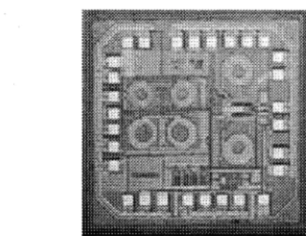
complex new functions above the ICs. However, spiral
inductors still remain the largest chip-area consumers (0.1
to 0.25mm2 space occupancy) and drastically penalize the
integration on silicon (Fig.1). On another hand, the
RF-industry is very conservative
and not ready for drastic
changes regarding
inductor design (solenoids).
Thus,
there is still an opened space to fill with ferromagnetic
spirals for down sizing even if they are not prone for a
natural use of ferromagnetic
films. More precisely,
adequate
size-reduction
with magnetic
materials
is
mandatory for spirals on silicon while keeping losses as
low as possible to the original air-core values. This needs
inductance (L) enhancement together with quality factor
(Q) considerations.
Fig. 1 Illustration of AIC High-Q air-core spirals using 4ƒÊm-thick Cu for LNA/VCO 2GHz-BICMOS circuits (spirals are 350 to 500 ƒÊm outer diameter, typically).
The goal of this paper is to illustrate significant improvements being possible with using high
magnetization (4ƒÎMs) ferromagnetic material such as FeHfN 1-4) . A high magnetization allows controlling both high permeability and high FMR frequency, which are the main conditions to increase L and Q. This paper will be divided in two parts. The first part will be focused on recent realizations based on the use of high magnetization FeHfN materials. Details for a variety of spirals will be
shown combining measurement and simulation results. The second part will introduce preliminary results
(simulations) with using both high magnetization and
high resistive FeHf(N)O materials. It is also raised the
question about the permittivity
of magnetic granular
materials which has not been taken into account for
ferromagnetic
spiral
considerations,
so
far.
The
permittivity of FeHf(N)O is shown for the first time based
on the realization of integrated capacitance on silicon.
2. Experiment
FeHfN, FeHfO and FeHfNO films were deposited at room temperature by reactive RF diode sputtering in a mixed Ar atmosphere containing N2 and/or O2. Oxidized
silicon substrates (100mm diameter) were used. The sputtering target consisted in FeHf 10wt.%. A substrate magnetic field (Hsub•`100Oe) was applied during
deposition. The sputtering conditions consisted in
3.10-3
mbar base-pressure,
50sccm
gas flow and 0.96W.cm-2
target power density. The nitrogenation and the oxidation were controlled by varying the N2 and O2 gas flow rates respectively. Saturation magnetization (47ƒÎMs), coercive field (Hc) and anisotropy field (Hk) were measured with a
vibrating sample magnetometer (VSM) and hard axis permeability with a RF permeameter. Resistivity (ƒÏ) was measured by four-point probe method. The highlight is on fine microstructure and chemical composition
investigations:
X-Ray Diffraction
(XRD),
Rutherford
Backscattering
Spectroscopy
(RBS), Nuclear Reactive
Analysis
(NRA),
Transmission
Electron
Microscopy
(TEM) and Energy Electron Loss Spectroscopy (EELS).
3.
FeHfN films and inductors
3.1 Single layer films
All the as-deposited films remain single bcc ƒ¿-Fe phase mainly (110) textured. N dissolves interstitially and leads to lattice expansion and grain size refinement5) down to •` 10nm (fig.2). When increasing the N2 flow rate, the initial columnar microstructure becomes nanocrystalline then amorphous-like including large precipitates of HfN (fig.3).
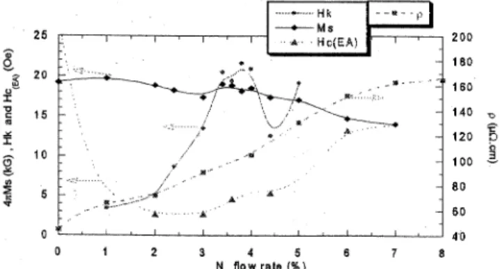
When considering magnetic properties, softness appears with the nanocrystalline structure with retaining high magnetization up to 7% N2 flow rate, as shown in figure 4. At larger flow rates, dense stripe domains form. They are also observed for a thickness superior to 150nm so films thickness is limited to 100nm to secure magnetic properties. In the nanocrystalline phase, induced uniaxial anisotropy (Hk) is promoted with N-incorporation.
(2) (3)
Fig. 2. and 3 XRD scans of 100nm-thick as-deposited FeHfN films
with different nitrogen flow rates and TEM and HR-TEM cross
section
images
of
Fe96.8Hf3.2 (a),
(Fe97.6Hf2.4)90N10
0
(b),
(Fe97.6f2.4)N14(c),
(Fe97.6Hf2.4)84N16(d)films and conical grain
EELS analysis (e).
Fig. 4 Dependence of 4ƒÎMs, HC(EA), Hk and ƒÏ on nitrogen flow ratio for 100nm-thick as-deposited FeHfN films.
Finally, the optimized single layer film consists in (Fe97.6Hf2.4)90N10 (at.%) with 4ƒÎMs = 19kG, Hk = 20Oe, α = 0 .012 and a resistivity p = 100ƒÊƒ¶.cm with a thickness restricted to 100 nm.
3.2
Lamination
and realization
To realize efficient ferromagnetic spirals, thick magnetic materials are required (typically =1 ƒÊm) 6). It is also required to prevent from eddy currents. Thus, laminated materials are of interest. In this work, we have considered laminations consisting in 10 alternations of
100nm-thick Fe97 .6Hf2.4)90N10 film separated with 50nm-thick SiO2 layer (fig.5). This material realizes a good compromise within magnetic, electrical and process suitability. It has been integrated on top of a variety of spiral inductors (fig.6). The realizations feature solid magnetic planes (SMP) with bi-directionality. The inductors have been realized with Above-IC technologies using thick-Cu (1 ƒÊm for the underpass and 5ƒÊm for the metal traces) and 5ƒÊm-thick BCB (Benzocylobutene) for spiral-insulation (fig.5).
3.3 RF measurements
S-parameters have been measured up to 10GHz with an on-wafer probe station. The investigation has been realized with 2-port coplanar inductors using bidirectional SMP on top of the spiral and including a variety of combination of designs (1.5, 3.5, 5.5 turns; round, square and octagonal geometries). This point is illustrated in figure 6. The equivalent series inductance (L) and quality factor (Q) have been extracted both for air-core and ferromagnetic inductors. Table I is a summary of the main results including the relative variations of L and Q with magnetic materials. Typically, the ferromagnetic spirals realize of about 28-33% increasing in L over the air-core value with Q of•` 10 at 1 GHz (de-embedded results) . Also, they all behave similarly whatever the combination of the geometries of the spirals with the SMP. Considering Q, one might note the maximum with magnetic materials is observed at relatively low frequency (•` 1GHz) while a high FMR-frequency has been realized (•` 6GHz). This has been explained in 7) on the base of the enlargement of current crowding with proximity effects
with magnetic materials. Also, as a major result, the use of laminated FeHfN materials having strong interlayer coupling have been found instrumental in realizing 100% spiral excitation on the hard axis with using single deposition only. This is highly advantageous with regards to mass-production. More details concerning this part are given in 1).
Fig. 5 FIB and TEM cross section images of a FeHfN film
integrated in a laminated solid magnetic plane (SMP) on top of a
copper spiral inductor.
Fig. 6 Optical images of the different coil geometries (Square,
Octagonal and Round) in air-core and using 2 or 4 solid
magnetic planes with different shapes (Trapezoid, Disc).
Table I
Inductance
(L) and quality factor (Q) values for
different spiral geometries (Square S, Octagonal O and Round R)
in air-core and using 2 or 4 solid magnetic planes with different
shapes (Trapezoid T, Disc D).
3.4 Simulation results
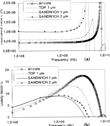
Air-core and ferromagnetic spirals have been simulated using Ansoft HFSS 9.0. This has been restricted to the case of the 3.5-turn square spiral which is representative. The corresponding results are shown in figures 7. The simulations use the experimental intrinsic LLG data including the FMR of the material. However, because of numerical limitations due to the finite mesh size, the laminated material is considered as a bulk material with an apparent equivalent higher resistivity in order to keep the skin depth the same as for the laminated material. For the on-top configuration, the results are in fairly good agreement with measurements (non
de-embedded) with L-enhancement of about 35% and Q of - 12 at 1 GHz. When considering the possibility of a sandwich configuration, the simulations indicate that a much larger increase in L is possible, typically 135%. However, the simulations also indicates that Q will be lowered of about 20% from the previous case because of the FMR frequency is reduced (4.5GHz instead of 5.5GHz) with the sandwiched spiral. This is due to magnetostatic coupling between the top and the bottom magnetic planes which reduce the demagnetizing field (Hd) responsible of the decrease of the FMR. Improvements on Q are still possible with restoring the FMR frequency at higher frequency. For example, the simulations show (fig. 7) that increasing the thickness of the magnetic materials (2ƒÊm instead of 1ƒÊm) would partially reinforce Hd and the FMR frequency while keeping L unchanged, the permeance being constant.
Adjusting the distance between the top and the bottom
magnetic planes has to be considered too.
(a)
(b)
Fig. 7 Simulated series inductance (a) and quality factor (b) for the 3.5-turn square spiral inductors using SMP with 100% HA-excitation in on-top (1ƒÊm-thick) and sandwich (1 and 2 ƒÊm-thick) configurations, respectively, (non-de-embedded data).
(a)
(b)
Fig. S Comparison on L and Q between a conventional 5.5 nH
air-core spiral and the SMP on-top spiral of same inductance and
between
a conventional
10 nH air-core spiral and the SMP
sandwiched spiral of same inductance, (non-de-embedded
data).
3.5 Resizing air-core spirals
Based on these results, simulations have allowed real illustrations of the re-sizing of the conventional air-core spirals 1) which is the goal of this work. A first example is shown in figure 8 where a 5.5 nH conventional spiral is compared with an equivalent ferromagnetic spiral using 1ƒÊm-thick magnetic material on top of the inductor. The ferromagnetic spiral realizes 25% saving in surface occupancy with similar L and Q. As a second example, it is shown that sandwiched spirals may compete with high inductance value air-core spirals (typically of 10 nH) with realizing •`50% surface reduction. To go further, it is suggested that the ultimate compactness for spirals would be realized by sandwiching the metal traces as close as possible. Indeed, this would allow inductance enhancement up to •`200%. However, this solution would require the use a granular material having similar magnetic properties as FeHfN, in order to cancel the excess capacitance with the metal traces. This point has motivated the following investigations on FeHfNO.
4.
FeHfNO
films
In
this
part,
co-incorporation
of
oxygen
with
nitrogen
in FeHf films is investigated
in order to raise the
resistivity
and to retain high magnetization
and adequate
soft magnetic
properties
8-9). In a first time, a comparison
has been made
between
pure-N2
and pure-O2
reactive
process, respectively.
In a second time, N2 and O2 reactive
gas have been mixed together.
In details, for a constant
amount
of O2
being
introduced
increasingly,
the
nitrogenation
of the film is controlled
by varying
the N2
flow
rate.
Microstructural,
magnetic
and
electrical
properties
of the films are summarized.
More details are
given in 10).
4.1
Comparing
FeHfN and FeHfO
FeHfO
and FeHfN
film properties
have
been
investigated
as a function of O2
and N2 flow rate,
respectively.
Pure O-incorporation
leads
to lattice
reduction and grain size expansion, typically, from 20 nm
to 45 nm (fig. 9 a and b). Also, it has been highlighted
that no iron-oxide forms. The lattice parameter of FeHfO
becomes similar to pure iron suggesting Hf atoms being
removed partially from the iron lattice towards grain
boundaries.
This
has
been
confirmed
by
TEM
observations indicating the presence of HfO2 at the grain
boundaries,
only. Thus, it is concluded that pure O2
reactive sputtering is suitable for preventing from massive
oxidation of iron and promoting preferential oxidation
with Hf at the grain boundaries. When comparing with
pure N2 process, it is shown that the dependences of the
grain size and the lattice parameter of the films with the
reactive gas flow rate are totally opposite. Finally FeHfO
films
consist
in large
columnar
(110)
bcc grains
containing almost pure iron and being surrounded by
HfO2.
In
contrast,
FeHfN
films
exhibit
fine
nanocrystallites scattered in an amorphous-like matrix.
(a)
(b)
Fig. 9 XRD scans of 100nm-thick as-deposited FeHfO films
with different oxygen flow rates (a) and TEM cross section
images of (Fe97.6Hf2.4)80O20
(b).
(a)
(b)
(c)
(d)
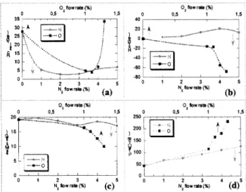
Fig. 10 Comparison between FeHfN and FeHfO films regarding
coercitif field along EA (a), anisotropy field (b), magnetization
(c) and resistivity (d).
The corresponding magnetic and electrical properties are described in figures 10. First, FeHfO films surprisingly present soft magnetism (fig.10a) while exhibiting larger grains with increasing O2. This contrasts with FeHfN whose origin of softness is with grain refinement with increasing N2. Second, FeHfO films show unexpected uniaxial anisotropies with Hk up to 80 Oe(fig.10b).
However, one must note that Hk is negative which means the easy axis is at 90•‹ from the expected direction with the substrate magnetic field. The origin of Hk with FeHfO being possibly related to magnetocrystalline constant changes totally differs from those with FeHfN (vanishing anisotropy) 11). Third, when comparing the saturation magnetization and the resistivity of the films (fig. 10c and d), one might be surprised that at low flow rates FeHfO and FeHfN behave similarly with retaining high 4ƒÎMs (=l5kG) and realizing moderate ƒÏ (=100 ƒÊƒ¶cm) which was not anticipated with O2. However, at high flow, as expected ƒÏ increases more sharply with O2 (=250 ƒÊƒ¶cm) and 4ƒÎMs also decreases more significantly (=l0kG). These results might be explained in relation with the opposite changes of the films microstructure with O2 and N2, respectively. Indeed, with O2, the unexpected high magnetization is consistent
with low iron oxidation, Hf removal from iron lattice and grain enlargement. On the other hand, all this points partially balance the expected natural increase in resistivity with oxidation which was expected with oxygen. With N2, N-incorporation is a priori more suitable for high 4ƒÎMs (no oxidation) but less suitable for high ƒÏ. However, because N-incorporation also results in severe grain refinement with a substantial increase in low 4ƒÎMs-amorphous-like matrix, it also leads to lowered magnetization and enhanced resistivity. Finally, these conclusions suggest that mixing N2 and O2 would be advantageous.
4.2 Mixing FeHfNO
Now, we investigate the effects of the combination of O2 together with N2.We use fixed O2 flow rates(0,1,1.1, 1.2 and 1.3%) while increasing the N2 ratio as for FeHfN. In these conditions, FeHfNO films retain the original bcc
FeHf phase with N dissolving interstitially. The increase in N2 still leads to lattice expansion and grain size reduction from tvpically 30 nm down to less than 5 nm
(fig.11).
Finally,
regarding the microstructure,
FeHfNO
films keep similar characteristics
as pure FeHfN films,
suggesting nitrogenation
superior
to oxidation.
Morein
details,
TEM observations
have revealed that
the addition
of O2 besides N2 still
promotes preferential
oxidation of
the surrounding amorphous matrix with HfO2 formation.
O2 might also contribute
to the enrichment with Hf of the
matrix but no clear
evidence has been found.
When using large N2 ratio (> 2%), the combination with O2 leads to a sharp transition from homogenous to heterogeneous microstructure which does not exist with FeHfN. The film microstructure consists in an
amorphous-like phase growing on top of a crystalline iron-oxide layer containing (FeHf)50O50 and no nitrogen.
These films do not exhibit soft magnetism anymore. Consequently, the range of control for the nanocrystalline phase, which encompasses high 4ƒÎMs and soft magnetic properties, is more restricted with N2 + O2 than with pure N2. At low N2 flow, addition of O2 let nitrogenation being superior to oxidation but this is reversed with large N2 flow.
(a)
(b)
Fig. 11 XRD scans of 100nm-thick as-deposited FeHfNO films
with different nitrogen flow rates and for 1.0% oxygen flow rate
(a) and TEM cross section images of Fe78Hf2O15N5 (b).
(a)
(b)
(c)
(d)
Fig. 12 HC(EA) (a), Hk (b), 4ƒÎMs (c) and ƒÏ (d) vs. nitrogen flow rates for 5 additional oxygen flow rates (as-deposited 100 nm-thick FeHfNO films).
Magnetic and electric properties of FeHfNO films agree with these microstructural changes as shown in fig.12. When N-atoms dissolve interstitially, the film
softness improves by grain refinement (fig.12a) and Hk increases with lattice dilation (but starting from negative
values with FeHfO as previously shown) (fig. 12b). As an advantage, the use of relatively low O2 flow rate besides nitrogenation shifts the resistivity by a factor 5 to 10. It is worth to note that the resistivity still linearly depends on N-incorporation (fig.12 d). When considering 4ƒÎMs, the trends are similar but on the opposite direction with a shift to lower values with increasing O2 (fig. 12c). In conclusion, the combination of N2 and O2 has confirmed the balance of the respective effects on the magnetic and electrical properties of FeHfNO. Thus, in contrast to pure FeHfO and pure FeHfN, the achievement of a compromise for high ƒÏ and 4ƒÎMs would be easier. This is confirmed partially with ƒÏ of -500 ƒÊƒ¶.cm and 4ƒÎMs of ∼10kG . However, besides the advantage of realizing very high resistivity (ρ ≧103μ Ω.cm),the dual reactive process
does not allow to retain adequate magnetization (4πMs≦ 7kG),yet.This requires further investigations.
43
Considerations
on permittivity
As FeHfNO
films
and
more
generally
granular
magnetic
films
may
exhibit
very high resistivity,
one
might ask about the permittivity
of such materials.
To our
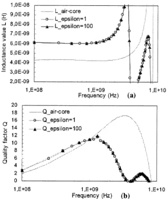
knowledge, this has been never investigated so far. For this purpose, capacitances have been fabricated on silicon with using FeHfNO films with ƒÏ 103ƒÊ ƒ¶.cm as the dielectric layer between two Pt electrodes. The results show that such film might exhibit very large permittivity with typically ƒÃ' of •` 200. Thus, when considering the use of the granular material having both high ƒÊ' and large ƒÃ' with spirals, both aspects have to be taken into account. Preliminary simulations have been realized based on the
3.5 turn square spiral as previously investigated but using l ƒÊ m-thick granular FeHfNO on top the spiral with 4ƒÎMs of 10kG, ƒÏ of 500 ƒÊ ƒ¶.cm and ƒÃ of 100 and 1 (no loss assumed). Also the distance between the magnetic material and the spiral has been reduced to 1 ƒÊ m (instead of 5ƒÊ m). As shown in fig.13, L-enhancement is around 42% over the air-core value. The quality factor increases of 38% at low frequency (< 800 MHz) and reaches maximum of 12 at 1.5 GHz. There are no obvious effects of on the L and Q values. But the interpretation of these results needs further investigations taking notably into account the dielectric losses ƒÃ".
5.
Conclusion
In this paper, we have first highlighted the use of high magnetization FeHfN laminated material for size reduction with spirals on silicon. Indeed, 25% to 50% surface saving have been shown and discussed with considerations both on L and Q. Then, conditions for an ultimate down sizing with L-enhancement up to 200% have been suggested based on the possibility of a material combining similar magnetic properties as FeHfN together with much higher resistivity. This was the main motivation for the second part of this work where the effect of O-addition besides N-incorporation for FeHfNO films has been detailed. It has been shown that each process leads to opposite consequences on the film microstructure but combine advantageously.
Thus, the nitrogen incorporation of the films with addition of small amount of oxygen remains superior and results in fine high 4ƒÎMs-nanocrystallites scattered in a preferentially oxidized matrix. This has led to a compromise with 4ƒÎMs of •` 10kG and ƒÏ of •` 500ƒÊ ƒ¶.cm which is better than those with pure FeHN and FeHfO. It is also shown that the dual reactive sputtering process is suitable for higher resistivity (ƒÏ = 103ƒÊ ƒ¶.cm) but it has not realized 4ƒÎMs above 8kG so far. In the final part, considerations on permittivity besides permeability with of granular films have been discussed. Indeed, permittivities of the order of 200 have been measured with FeHfNO. This result reveals that such film is both magnetic and dielectric and that this duality has to be taken into account for the optimization of future ultimate compact ferromagnetic spirals on silicon.
(a)
(b)
Fig. 13 Simulated series inductance (a) and quality factor (b) for the 3.5-turn square spiral inductors using 1 ƒÊm-thick granular FeHfNO SMP with ƒÃ = 100 and ƒÃ=1 separated from the metal trace by 1ƒÊm thick BCB and comparison with the corresponding air-core inductor (de-embedded data).
REFERENCES
1) B. Viala, S. Couderc, A. S. Royet, P. Ancey, G. Bouche, "Bi-Directional Ferromagnetic Spiral Inductors Using Single Deposition" , Intermag Asia - 2005, accepted in IEEE Trans. Mag., sept. 2005.
2) K.H. Kim, H. W. Choi, J. Kim, S. R. Kim, K. Y. Kim, S. H. Han, and H. J. Kim , "Magnetic Properties and Reliabilities of FeXN(X = Ti, Al, Hf , CoHf, CrHf) Nanocrystalline Thin Film Head Materials", IEEE Trans. Mag. 36, (5), pp..2656-2659, 2000. 3) K.H. Kim, Y.H. Kim, J. Kim, S.H. Han, H.J. Kim, "Effect of
sputtering input power on structural inhomogeneities in as sputtered FeHfN thin films", J. Mag. Mag. Mat., 215, pp.368-371, June 2000.
4) K.H. Kim, Y.H. Kim, J. Kim, S.H. Han, H.J. Kim, "Thickness effect on magnetic properties in nanocrystallineFeHfN thin films" , J. Mag. Mag. Mat., 215, pp. 428-430, June 2000
5) G. De Vries, Physica, 25, pp. 1211, 1959.
6) B. Viala, A.S. Royet, R. Cuchet, M. Aid, P. Gaud, O. Valls, M. Ledieu and O. Acher, "RF Ferromagnetic Inductors on Silicon" , IEEE Trans. Mag., 40, (4), pp.1999-2001, July 2004.
7) A-S. Royet, B. Viala, S. Couderc and B. Orlando, "Investigation of " Proximity Effects in Ferromagnetic Inductors with Different Topologies: Modeling and Solutions" , Trans. Magn. Soc. Jap. 2005.
8) J. Huijbregtse, and al., "High-frequency Permeability of Soft-magnetic Fe-Hf-O films with High Resistivity" , J. Appl. Phys., 83, (3), pp.1569-1574, February 1998.
9) Makino, A. Inoue, T. Masumoto, "Nanocrystalline Soft Magnetic Fe-M-B (M = Zr, Hf, Nb), Fe-M-O (M = Zr, Hf, rare earth) Alloys and their Applications" , Nanostructured Materials, 12, pp. 825-828, 1999.
10) S. Couderc, B. Viala, P. Ancey, G. Bouche, •á FeHfN and FeHfNO Soft Magnetic Films for RF Applications" , Intermag Asia - 2005, accepted in IEEE Trans. Mag., sept. 2005..
11) H. Hoffmann, "Magnetic properties of thin ferromagnetic films in relation to their microstructure" , Thin Solid Films, 58, pp. 223-233,
1979.
Received Jun. 06, 2005; Accepted Sep. 16, 2005