九州大学学術情報リポジトリ
Kyushu University Institutional Repository
先細末広ノズル内のトランソニックトーン発生に関 する研究
申, 昇永
https://doi.org/10.15017/1398550
出版情報:Kyushu University, 2013, 博士(工学), 課程博士 バージョン:
権利関係:Fulltext available.
i
A Study on
Transonic Tone Generation in Convergent-Divergent Nozzles
Dissertation
Submitted to
Department of Energy and Environmental Engineering on Graduate School of Kyushu University
in Partial Fulfillment of the Requirements for the Degree of Doctor of Engineering
By
Seungyoung Shin
Kyushu University
October 2013ii
Abstract
When a supersonic flow condition is non-isentropic condition that a shock wave occurs within the divergent section of convergent-divergent nozzle, transonic tone can occur at low nozzle pressure ratios. And the tone is distinct from other jet noise components. The main objectives of the present thesis were to get better understanding on the acoustic characteristics and generation mechanism of transonic tone in supersonic nozzle experimentally.
First, the effects of nozzle-lip thickness on the acoustic features of transonic tone have been investigated to check a location of the noise source. Far-field acoustic measurements are accomplished to obtain the noise spectra of the supersonic jets, which are issued from a supersonic nozzle with a design Mach number of 2.0. The acoustic characteristics of the supersonic jet, such as the transonic tone or screech tone frequency and amplitude will be discussed briefly in this thesis using the acoustic measurement results. The results obtained obviously show that the acoustic characteristics of transonic tone are differ from the screech tone and distinctly from the screech tone, it is found that the transonic tone has internal noise source.
To understand the transonic tone generation mechanism, the first shock wave the transonic tone had tried to correlate with flow oscillations. In particularly, the first shock wave oscillations and wall static fluctuations are considered with high speed video camera and simultaneous measurement system. And the results show that the frequencies of the shock wave and wall static pressure fluctuations correspond to the transonic tone and it is expect that a feedback loop between the shock wave and the nozzle exit.
In the present thesis, a tone reduction method is also considered by extension of the nozzle-lip length in 2-dimensional supersonic nozzle. And the transonic tone reduced at stage 1 about 5~10 dB when the nozzle-lip attached at the side of large separation zone in the nozzle and the extended nozzle-lip also affected the
iii
shock wave oscillations, wall static pressure fluctuations and cross-correlations between the shock wave and the wall static pressure fluctuations.
iv
Acknowledgement
I would like to my hearty thanks to my supervisor, Professor Toshiyuki Aoki for his guidance and encouragement to accomplish the present work both inside and outside the laboratory over the years. I also sincerely thank the committee members of my manuscript, Professor N.obuhiko Yamasaki and Professor Taro Handa for taking valuable time out their busy schedules to provide advice and suggestions to my work.
I want to express my special thanks to Dr. Makiko Yonamine and Dr. Sungjae Jung for their technical advice and encouragement during my first year for a doctorate. I also wish to express my gratitude to Mr. Nobuaki Kondoh who made a more complete work by providing much technical assistance. In addition, special thanks to graduate students, Mr. Akira Tokumoto, Mr. Yuya Yamasita, Mr.
Hiroki Kuguyama, Mr. Akira Matunaga and Mr. Hiroyuki Marubayashi for their assistance, cooperation and kindness over the course of my graduate study.
I am also thankful to my special friends Youngjin Lee, Yongbaek Kang, Choongsik Kim and Fukuoka Central Church families for their constant encouragement, prayer and help with material and emotional support for life in Fukuoka.
I would like to express my gratitude toward my parents and parents-in-laws their un-failing love, patience, support and prayer through a long educational process. Finally, I am deeply thankful to my lovely wife and baby inside her for being my great delight, comfort and encouragement.
October, 2013
v
Contents
Abstract ii
Acknowledgement iv
Contents iii v
List of Figures viii
Nomenclature xi
1 Introduction
1.1 Background ··· 1
1.1.1 Supersonic Jet Noise ··· 1
1.1.2 Motivation ··· 5
1.2 Objectives of Research ··· 6
1.3 Overview of Thesis ··· 6
2 Survey of Previous Work
2.1 Introduction ··· 112.2 Staging Phenomenon and Tone Generation Condition··· 11
2.3 Prediction of Transonic Tone Frequency ··· 12
2.4 Reduction of Transonic Tone ··· 13
3 Experimental Apparatus
3.1 Anechoic Test Room ··· 173.2 High Pressure Air Supply ··· 18
3.3 Convergent-Divergent Nozzle ··· 18
3.4 Schlieren Optical System ··· 19
3.5 Pressure Transducer and Microphone ··· 20
vi
4
Acoustic Characteristics of Transonic Tone and Effect of Nozzle-Lip Thickness on Transonic Tone in Axisymmetric Nozzle
4.1 Experimental Conditions··· 25
4.2 Acoustic Characteristics of Transonic Tone··· 26
4.3 Effect of nozzle-lip length on Transonic Tone ··· 27
4.4 Summary··· 28
5 Transonic tone in 2-Dimensional Supersonic Nozzle
5.1 Experimental Conditions ··· 425.2 Acoustic Characteristics··· 43
5.3 Flow Visualization ··· 44
5.4 Shock wave oscillation ··· 44
5.5 Wall Static Pressure Fluctuation··· 45
5.6 Cross-correlation··· 46
5.7 Summary··· 48
6 Effect of Nozzle-Lip Length on Shock-Induced Separated Flow and Transonic Tone in 2-Dimensional Supersonic Nozzle
6.1 Experimental Conditions ··· 656.2 Effects on The Transonic Tone Reduction ··· 66
6.3 Flow Visualization ··· 67
6.4 Effects on The First Shock Wave··· 68
6.5 Effects on Wall Static Pressure Fluctuation··· 70
6.6 Effects on Cross-correlations ··· 71
6.7 Summary··· 72
7 Conclusions
vii
7.1 Conclusions ··· 105 7.2 Future Work ··· 107
References
··· 109viii
List of Figures
1.1 Far-field narrow-band noise spectrum of an imperfectly-expanded supersonic jet measured by Seiner & Yu (1984). Microphone is located at 150° from the jet axis
1.2 Overall sound pressure levels of unheated jet from a convergent-divergent nozzle (C-D) with a design Mach number Md=1.5 at 150° to the jet axis (Seiner & Yu, 1984) : , imperfectly-expanded case ; , perfectly- expanded case
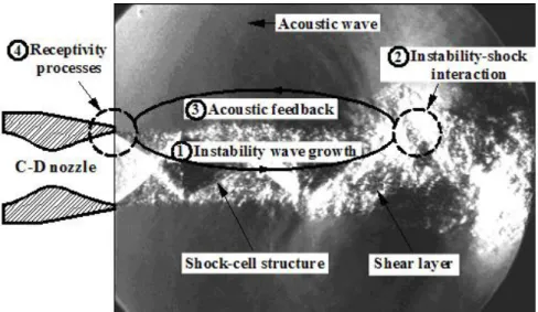
1.3 Fundamental mechanism of screech tone feedback loop. This is the flow visualization picture for imperfectly-expanded jet (Mj=1.51) obtained from the present work
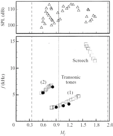
2.1 Variation of frequency and amplitude of acoustic tones with Mj (Zaman, Dahl, Bencic & Loh 2002)
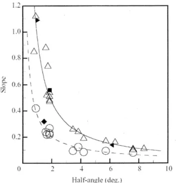
2.2 Variations of slope of fNL/a0 with Mj for various nozzles as a function of the half-angle of divergence (θ) (Zaman, Dahl, Bencic & Loh 2002)
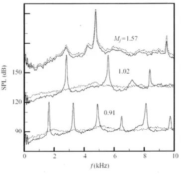
2.3 Tripped boundary-layer effect (dotted lines) on resonance in sound pressure level (Zaman, Dahl, Bencic & Loh 2002)
3.1 Schematic diagram of experimental facility (unit : mm) 3.2 Details of a convergent-divergent nozzle (unit : mm) 3.3 Spark schlieren optical system
3.4 Schematic diagram of experimental procedure 4.1 Microphone locations
4.2 Arrangement and picture of a baffle plate (unit : mm)
4.3 Typical far-field noise spectrum measured at r/D=50 and θ=96° (NPR= 1.8) 4.4 Far-field noise spectrum variation with NPR( r/D=50 and θ=96°~60°)
4.5 Peak frequency distribution of transonic tone and screech tone (r/D=50 and θ=96°)
4.6 Relationship between transonic tone amplitude and Mj( r/D=50 and θ=96°)
ix
4.7 Relationship between screech tone amplitude and Mj (Miyazato et al., 2004) 4.8 Variation of transonic tone amplitude with t/D
4.9 Variation of screech tone amplitude with t/D for over-expanded and under- expanded jets
4.10 Variation of transonic tone frequency with t/D
5.1 Schematic diagram of 2-dimensional convergent-divergent nozzle 5.2 A photo of the 2-dimensional convergent-divergent nozzle
5.3 Sound pressure level spectrum(2-D nozzle, θ=60°) 5.4 Transonic tone frequency variation with NPR
5.5 Schlieren images showing limit position of shock waves 5.6 Oscillations of the first shock wave
5.7 Power spectral density of the first shock wave oscillations 5.8 Power spectral density of wall static pressure fluctuation
5.9 Frequency comparison between transonic tone and first shock wave oscillation and wall static pressure fluctuation
5.10 Cross-correlations at typical NPR(NPR=1.7, 2.0 and 2.8)
5.11 Plots of peak cross correlation coefficients(Shock wave vs wall static pressure)
5.12 Plots of peak cross correlation coefficients(Wall static pressure vs sound pressure)
5.13 Plots of peak cross correlation coefficients (Shock wave vs sound pressure) 6.1.1 Comparisons of sound pressure level whit flow direction(Normal nozzle) 6.1.2 Comparisons of transonic tone reduction(Case of the upper-side nozzle-lip
extension)
6.1.3 Comparisons of transonic tone reduction(Case of the bottom-side nozzle-lip extension)
6.1.4 Comparisons of transonic tone reduction(Case of the both sides of nozzle-lip extension)
6.2.1 Bar-plots of transonic tone reductions at typical NPR(6mm-nozzle-lip attached)
x
6.2.2 Bar-plots of transonic tone reductions at typical NPR(12mm-nozzle-lip attached)
6.3 Schlieren images showing limit position of shock wave 6.4 Traces and displacement histogram of the first shock wave
6.5 The variation of the first shock wave position from the nozzle exit 6.6 Long-stay position variations of the first shock wave
6.7 Maximum displacement of the first shock wave 6.8 PSD distribution of the first shock wave oscillation 6.9 PSD comparison between wall static pressures
6.10 PSD distribution of wall static pressure(6mm from nozzle exit)
6.11 The variation of the first shock wave position from the nozzle exit Typical cross-correlations
List of Tables
4.1 Detailed dimensions of baffle plates (unit : mm) 5.1 Delay time and velocity at peak cross correlation
xi
Nomenclature
a sound speed
D downward or down-side
D nozzle exit diameter or diameter
f frequency
L length of nozzle-divergent section
M Mach number
N normal
NPR nozzle pressure ratio
P pressure
PSD power spectral density R cross-correlation coefficient SPL sound pressure level
t thickness
U upward or upper side
r radius from nozzle exit
X distance along the jet axis from nozzle exit γ specific heat ratio
θ angle of acoustic measurement installed or half angle of nozzle- divergence section
τ time delay
Subscripts
0 stagnation state in the plenum chamber
a ambient state
b baffle
h half
i inside or sampling step
xii
j fully expanded condition of the jet
m microphone
m odd harmonics number
o outside
p pressure sensor
p peak
s shock wave
1
Chapter 1
Introduction
1.1 Background
1.1.1 Supersonic Jet Noise
Supersonic jets have long been used in many diverse fields of engineering applications such as supersonic aircrafts (Ennix et al., 1993), jet propulsion thrust vectoring (Strykowski, 1996), fuel injectors for supersonic combustion (Ramesh et al., 2000), soot blower devices (Jameel et al., 1994), coating technology for structural materials (Postel & Heberlein, 1998), supersonic ejectors (Bartosiewicz et al., 2005), jet pumps (Eames, 2002), etc. Until now, a great deal of studies has been experimentally and theoretically carried out to obtain detailed features of supersonic jet. It has been well known that the time-mean structure of supersonic jet is determined by nozzle pressure ratio and nozzle configuration (Love et al., 1959 ; Addy, 1981 ; Bülent Yüceil & Volkan Ötügen, 2002).
When a supersonic jet is issued from a nozzle exit, the high frequency noise problems occur. Many research have been conducted to understand the noise characteristics and generation mechanism including the appropriate noise control methods in suppressing the supersonic jet noise. Recently, the supersonic jet noise is being a very important issue to be resolved from the practical point of view of performance of fluidic device (Li & Halliwell, 1985 ; Krothapalli et al., 1986 ; Meier et al., 1990) as well as environmental noise problem (Thomas et al., 2002). However, it is not simple to understand and to control the jet noise generation because the understanding of jet noise is tied to the understanding of turbulence in jet flows.
Since Lighthill (1952, 1954) first introduced his acoustic analogy theory in
CHAPTER 1.Introduction 2
1952 and 1954, jet noise has been a topic of interest for many researchers. The idea that the sound radiated from aerodynamics flows can be modeled as a distribution of quadrupole sources has led to many different models and theories in order to predict the noise from jet flows. He established that the acoustic power radiated from a jet should scale as the eighth power of the jet velocity. While Lighthill’s original theory is valid only for subsonic jet, other researchers have extended the previous theoretical studies of Lighthill into the range of supersonic jet velocities. In particular, Ffowcs Williams (1963) showed how turbulence con- vected downstream at a relatively high speed can be very strong source of noise in the far-field, and found that for very high speed jets, the acoustic power of the radiated noise should scale as the third power of the jet velocity.
It is now well known that the supersonic jet noise consists of three major components (Tam, 1995) : the turbulent mixing noise, the broadband shock- associated noise, and the screech tones. A typical far-field noise spectrum of an imperfectly-expanded supersonic jet in the upstream direction is described in Fig.1.1. The turbulent mixing noise is usually observed over a broad spectral hump centered around a Strouhal number (fD/uj) of 0.1-0.2. The broadband shock -associated noise appears at a higher frequency than that of the turbulent mixing noise. The screech tone is observed between the mixing noise and the broadband shock noise. The mixing noise is generated in subsonic jet as well as supersonic jet, but other two noise components appear only in an imperfectly expanded supersonic jet which has a quasi-periodic shock cell structure in the jet plume.
The turbulent mixing noise of supersonic jet is produced by the fine-scale turbulence and the large-scale turbulence propagating downstream at supersonic Mach number relative to the ambient sound speed. The large-scale turbulent structures are capable of producing intense Mach wave radiation. Surprisingly, the existence of large-scale structures was not known until the early 1970s with works such as Crow & Champagne (1971), Brown & Roshko (1974), Winant &
Browand (1974), and Browand & Weidman (1976). Depending on the references, researchers refer to the largest coherent scales within a jet flow as : large-scale
CHAPTER 1.Introduction 3
turbulent structures, large vortices, large eddies, coherent structures, etc.
For supersonic jets, the intensity as well as both the directional and spectral characteristics of the turbulent mixing noise strongly depend on the jet Mach number and the jet temperature (Fisher et al., 1973 ; Tanna, 1977a). The turbulent mixing noise increases as the jet Mach number increases. As the jet temperature is increased, the mixing noise also increases due to the increase in jet velocity with heating. Furthermore, Ffowcs Williams et al. (1975) and Krothapalli et al.
(2000a) studied a particular turbulent mixing noise, referred to as crackle, which is generated due to the micro explosions of the cold ambient fluid entrained into the hot jet flow.
On the other hand, when a convergent nozzle is operated at supercritical pressure ratio (under-expanded), or when a convergent-divergent (C-D) nozzle is operated at off-design Mach number (over-expanded or under-expanded), a shock cell structure is formed in the jet flow. This causes the shock-associated noise, in addition to the basic turbulent mixing noise. Figure 1.2 shows the noise intensity of a supersonic jet from a convergent-divergent nozzle (Seiner & Yu, 1984).
Since there is no shock-associated noise when a jet is correctly-expanded, the solid line and black circles represents the minimum noise level (consisting of only the turbulent mixing noise) of the jet at a given fully expanded jet Mach number. When the jet is imperfectly-expanded, the total jet noise consists of both the mixing and shock-associated noise components, as shown in Fig.1.2.
The shock-associated noise can be divided into two distinct components. The first component is broadband in nature, and is usually known as the broadband shock-associated noise. The broadband shock-associated noise is generated by the weak interaction between the downstream propagating large-scale turbulence structure of the jet flow and the quasi-periodic shock cell structure. The second component is discrete in nature, usually with several harmonics, and commonly referred to as the screech tone. The generation of screech tone is due to the acoustic feedback phenomenon, as shown in Fig.1.3.
The broadband shock-associated noise was first identified by Harper Bourne
CHAPTER 1.Introduction 4
& Fisher (1974). Since then, it has been studied experimentally by a number of researchers, such as Tanna (1977b), Tam & Tanna (1982), Norum & Seiner (1979, 1982a), and Seiner & Yu (1984). These researches have provided much detailed information on the acoustic characteristics of the broadband shock-associated noise. Harper Bourne & Fisher (1974) developed the theoretical model for the prediction of the characteristics of shock noise, by regarding each shock cell end as a compact source of acoustic radiation. They also showed that the intensity of the broadband shock-associated noise is proportional to the fourth power of the shock strength. Its noise spectrum is distinct from that of the turbulent mixing noise, as shown in Fig.1.1, and is characterized by a peak. The frequency of this peak varies with angle in the manner of a Doppler shift, and is proportional to the jet velocity and inversely proportional to the shock spacing.
The screech tone phenomenon was first described by Powell (1953a, b) as arising through an acoustic feedback mechanism. Figure 1.3 shows the generation mechanism of screech acoustic feedback loop : (1) A disturbance in the jet shear layer is convected downstream and is amplified in passing downstream. (2) The amplified large-scale turbulence structure interacts with the shock cell structure, scattering intense sound waves at that point. (3) These acoustic waves propagate through the ambient fluid in the upstream direction and interact with the jet shear layer close to the nozzle exit. (4) This interaction gives rise to a new downstream traveling disturbance that continues the cycle (receptivity processes).
Independently of the general noise components, the transonic tone can occur at low nozzle pressure ratios when a shock wave occurs within the divergent section of convergent-divergent nozzle without any abrupt area change. Such transonic tone through `whistler nozzles' has been studied by Hill & Greene (1977) and by Hussain & Hasan (1983). Resonance of similar flows discharging through a duct or `ejector', involving choked and supersonic conditions, have been studied by Witczak (1977) and by Krothapalli & Hsia (1996). The resonance in many cases could be traced to a coupling between the duct acoustic modes and the instability of the shear layer originating from the sudden expansion.
CHAPTER 1.Introduction 5
1.1.2 Motivation
Transonic tone can occur at low nozzle pressure ratios when a shock wave occurs within the divergent section of convergent-divergent nozzle without any abrupt area change. In the present study, the transonic tone also observed in convergent-divergent nozzles designed by characteristic method with a smooth convergence to the throat and then a smooth divergence up to the exit without any abrupt area change when a shock exists within the diverging section of the nozzle. In this range of operating conditions the flow often locks on to a resonance accompanied by very loud tones.
The ‘transonic tone’ or ‘transonic resonance’ was named by Zaman et al.(Zaman & Dahl 2002) at the first. Prior to that, of course, acoustic tones which occur at intermediate range of pressures when a shock exists within the diverging section of a nozzle have been noted, for example, in convergent-divergent nozzles as ‘a precursor to screech’ (Seiner J. M. 1998) as well as in subsonic diffusers (Zaman & Dahl 1990). Especially, a self-excited flow oscillation was observed from a series of experiments with two-dimensional diffuser at transonic conditions (Chen, Sajben & Kroutil 1979; Sajben, Bogar & Kroutil 1980; Bogar, Sajben & Kroutil 1983; Hsieh & Coakley 1987).
A few experimental and numerical researches on the diffusion of the transonic tone have been carried out (Bogar, Sajben & Kroutil 1983; Loh &
Zaman 2002). In particular, Zaman et al. investigated the characteristics of the transonic tone in various nozzle conditions, and provided correlation equations to predict the frequency from a collection of data for single round nozzles (Zaman, Dahl, Bencic & Loh 2002). Moreover, they showed that transonic tone takes place similarly to the (no-flow) longitudinal acoustic resonance of a conical section with one end closed and the other end open. However, it remains unclear under what process the transonic tone can occur in actual flow complicated by shock oscillation and shock wave/boundary layer interaction phenomenon.
CHAPTER 1.Introduction 6
1.2 Objectives of Research
The primary objectives of this thesis are to investigate the characteristics and generation mechanism of transonic tone at low nozzle pressure ratios when shock wave occurs within the supersonic nozzle. These objectives are accomplished by experimental works. Three major objectives of the present work are listed as follows:
Acoustic characteristics of transonic tone and effect of nozzle-lip thickness on transonic tone in axisymmetric nozzle – It may be helpful to consider some important characteristics of transonic tone. One of them, for example, is which region the transonic tone source exist. The objective of this part is to understand the acoustic characteristics of transonic tone and its variation according to nozzle pressure ratio and to examine which region has the transonic tone source by comparing the nozzle-lip thickness effects on the transonic tone frequency and amplitude with screech tone’s one.
Transonic tone in 2-dimensional supersonic nozzle – This objective is to investigate the relationship between the transonic tone and the first shock wave oscillation or wall static pressure fluctuation when the transonic tone occurs. There are some attempts to correlate the transonic tone and flow oscillation in 2-dimensional supersonic nozzle.
Effect of nozzle-lip length on transonic tone in 2-dimensional supersonic nozzle – A new control technique of transonic tone is experimentally studied by changing the nozzle lip length. This objective is to examine the effect of nozzle-lip length on transonic tone as a supplement the validity of feedback mechanism of transonic tone. The variation of the first shock wave oscillation and wall static pressure fluctuation according to nozzle-lip length will also be discussed.
1.3 Overview of Thesis
The background and research progress of general supersonic jet noise and
CHAPTER 1.Introduction 7
transonic tone have been briefly explained in Chapter 1. The motivation and major objectives of the present thesis are also described in this chapter. Some brief reviews of transonic tone in supersonic jet are followed in Chapter 2. The fundamental acoustic characteristics of transonic tone and its control techniques are explained in this chapter. Chapter 2 will be helpful in getting the insight into the present situation of researches related to transonic tone, and understanding the needs for the present study.
Chapter 3 gives a full description of the facility and experimental apparatus used for the present work. This includes a description of high pressure air supply system, anechoic chamber, nozzle configuration, high-quality spark schlieren optical system and high speed video camera. The data acquisition devices such as a microphone and a pressure transducer are also described.
The results and discussion of the actual experimental works begin in Chapter 4. In this chapter, acoustic characteristics of transonic tone and the effect of nozzle-lip thickness on the transonic tone in axisymmetric convergent-divergent nozzle are discussed with comparing the acoustic characteristics of transonic tone to screech tone according to the nozzle-lip thickness variation.
Chapter 5 describes an experimental work to investigate characteristics and generation mechanism of the transonic tone in 2-dimensional supersonic nozzle.
In particular, the frequency of the first shock wave oscillation and wall static pressure fluctuation are analyzed and tried to correlate to the transonic tone and a feedback mechanism for generation of transonic tone is proposed.
Chapter 6 describes an experimental work to investigate the effect of nozzle- lip length on transonic tone in 2-demensional supersonic nozzle. Especially, with considering the large separation zone location from which the feedback loop development is expected, the effect of nozzle-lip length on the transonic tone, the first shock wave oscillation, wall static fluctuation and variation of the cross- correlations will be reported.
Finally, Chapter 7 summarizes the important findings obtained from Chapter 4, 5 and 6. Some recommended directions for future research are also suggested.
CHAPTER 1.Introduction 8
Figure 1.1 Far-field narrow-band noise spectrum of an imperfectly-expanded supersonic jet measured by Seiner & Yu (1984). Microphone is located at 150°
from the jet axis
CHAPTER 1.Introduction 9
0.0 0.5 1.0 1.5 2.0 2.5
(M
j2- 1)
1/290 100 110 120 130 140
S P L ( d B )
Mj=Md=1.5
Under-expanded Over-expanded
Mixing noise Total noise for C-D nozzle
(shock noise & mixing noise)
Figure 1.2 Overall sound pressure levels of unheated jet from a convergent- divergent nozzle (C-D) with a design Mach number Md=1.5 at 150° to the jet axis (Seiner & Yu, 1984) : , imperfectly-expanded case ; , perfectly-expanded case
CHAPTER 1.Introduction 10
Figure 1.3 Fundamental mechanism of screech tone feedback loop. This is the flow visualization picture for imperfectly-expanded jet (Mj=1.51) obtained from the present work
11
Chapter 2
Survey of Previous Work
2.1 Introduction
The resonance phenomenon in nozzle flows has been studied in the past by many researchers not only because of academic interest, but also for its significance in many engineering applications ranging from mixing (Hill & Greene 1977) and jet noise control (Krothapalli & Hsia 1996) to buffeting in external flows (Mabey 1989) and rocket engine instability (Schwane,Wong & Torngren 2002). The occurrence of resonance can be self-excited or driven by external unsteady loads,
or combination of these mechanisms. For instance,in the case of convergent- divergent nozzles without any abrupt area change,the nozzles are under a transonic flow condition at a pressure ratio much lower than the design value, and flow separation takes place just downstream of the shock wave. Consequently, self-exited resonance and tones are encountered with such a nozzle condition.
These kind of phenomenon has been studied experimentally (Zaman,Dahl, Bencic & Loh 2002,Hunter 2004,Sajben & Kroutil 1980),as well as numerically (Hunter 2004,Loh & Zaman 2002). Zaman et al.(Zaman,Dahl, Bencic & Loh 2002) provide a complete overview of this activity.
2.2 Staging Phenomenon and Tone Generation Condition
According to Zaman(Zaman,Dahl, Bencic & Loh 2002), the resonant frequencies appears in multiple modes, with the fundamental order mode corresponding to a standing wave of a quarter-wavelength and higher order modes exist only in odd harmonics at a low nozzle pressure ratio. The Fig.2.1
CHAPTER 2. SURVEY OF PREVIOUS WORK 12
shows the tone frequency f as the increasing and stage-jumping resonance with increasing nozzle pressure ratio. The vertical lines demarcate flow regimes determined from one-dimensional nozzle flow analysis, based simply on the throat-to-exit area ratio. From the left, first (dashed line), the second (dotted line) and the third (chain-dashed line) represents respectively the choking condition, exit shock condition and design condition when the flow is perfectly expanded. It seems from the boundaries in Fig.2.1 that the resonance could take place when a shock existed within the divergent section or when the flow was in the early stage of overexpansion. However, it turned out that one-dimensional analysis grossly under-predicts the location of the 'dotted' boundary, and the resonance always involves a shock within the divergent section.
2.3 Prediction of Transonic Tone Frequency
Zaman et al. (Zaman,Dahl, Bencic & Loh 2002) also suggested the empirical equations for the prediction of transonic tone frequency. It comes out that the resonant frequency fN is strongly dependent on the divergent angle of the nozzle for smaller than 2 degree, as shown Fig.2.3. The curves in Fig.2.3 are least- squares-fits through the data for the round nozzle cases(open symbols). From the fitted curves the following equation is obtained, with expressed in degrees:
5 , 3 , 1 ), 1 )(
( )
( 2
1 0
C C M m
ma l f
j h h
N
where C1()=0.2980-0.370, C2()=0.9520-1.029 for stage 1, and C1()=0.2210-
0.325 , C2( )=0.3630 -0.875 for stage 2. This equation was provided for the
prediction the resonance frequency from a collection of data for axisymmetric nozzles. The throat-to-exit axial length (l) and the half angle of divergence (h)
are used to characterize the overall geometry of the divergent section.
CHAPTER 2. SURVEY OF PREVIOUS WORK 13
2.1 Reduction of Transonic Tone
Zaman et al. showed that the acoustic resonance phenomenon was suppressed significantly by a disruption of the azimuthal coherence of unsteadiness in the boundary layer upstream or downstream of the shock induced separation (Zaman, Dahl, Bencic & Loh 2002). It was found that the transonic tone sufficiently reduced with only installing some trip around the throat or installing some tabs in the boundary layer of the exit but the latter resulted in changing the flow state, directly. Sound pressure level spectra, with and without boundary layer trips are shown in Fig. 2.4. The trip was composed of 4.5 in. wide pieces of adhesive tape (approximately 0.003 in. thick) placed close to but sufficiently upstream of the throat so that there was no change in the minimum area. These were spaced equally around the periphery. It can be seen that, at the highest Mj, there is no effect on screech. This is expected because screech occurs due to a feedback loop external to the nozzle. However, the trip essentially eliminates the transonic tones in this case, at the lower values of Mj.
CHAPTER 2. SURVEY OF PREVIOUS WORK 14
Figure 2.1 Variation of frequency and amplitude of acoustic tones with Mj
(Zaman, Dahl, Bencic & Loh 2002)
CHAPTER 2. SURVEY OF PREVIOUS WORK 15
Figure 2.2 Slope variation of fNl/a0 versus Mj for various nozzles, as a function of the half-angle of divergence(θ); △-stage1,
○
-stage2(Zaman, Dahl, Bencic & Loh 2002)
CHAPTER 2. SURVEY OF PREVIOUS WORK 16
Figure 2.3 Tripped boundary-layer effect on resonance in sound pressure level;
dotted line-tripped case, solid line-normal case (Zaman, Dahl, Bencic & Loh 2002)
17
Chapter 3
Experimental Apparatus
This chapter describes the experimental apparatus used in order to investigate the flow and acoustic characteristics of supersonic jets, including an anechoic test room, high pressure air supply, a supersonic nozzle, a schlieren optical system and a microphone. While the supersonic jet is exhausting into the anechoic test room from the nozzle exit, the flow visualization, wall static pressure and acoustic measurements are accomplished.
3.1 Anechoic Test Room
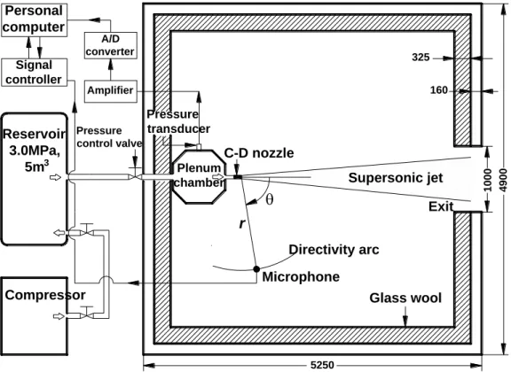
The present experimental works are conducted in an anechoic test room that is schematically shown in Fig.3.1. The anechoic test room has a dimension of 5.3m×4.9m×4.9m and is covered with sound absorption material (glass-wool foam) of a 325mm thickness. The acoustical foam is designed to absorb 95% of the incident noise for frequencies over 500Hz. According to some preliminary acoustic tests, the present test room is anechoic for all frequency components above approximately 120Hz and has the back ground noise of about 10dB.
At the end of the test room, the jet flow enters the exit of the test room which is used to control the ambient pressure in the test room to atmospheric condition.
The ambient pressure and temperature in the test room are measured at pa=101.3kPa and Ta=293K. All experimental devices have been set up to make simultaneous measurement and to control by personal computer installed externally.
CHAPTER 3. Experimental Apparatus 18
3.2 High Pressure Air Supply
A piston-type air compressor is capable of supplying air at a maximum storage pressure of 3MPa. A high pressure storage tank provides a total capacity of 5m3. After leaving the high pressure storage tank, compressed dry air enter the plenum chamber, in which a honeycomb system reduces flow turbulence. A circular convergent-divergent nozzle and two-dimensional convergent-divergent nozzle are installed on the end of the straight pipe. For the circular nozzle, the end wall of the blowdown plenum chamber is connected with a circular straight pipe which has a length of 100mm and an inner diameter of 28mm, as shown in Fig.3.1. And the two-dimensional nozzle is connected with a rectangular straight pipe which has a length of 120mm, an inner height of 16.2mm and an inner width of 30mm. The pressure inside the plenum chamber is controlled by a pressure regulator valve which is located upstream of the plenum chamber.
The temperature in the plenum chamber is measured by using a thermocouple, and it maintains constant at room temperature (approximately 293K) during test.
The pressure is measured by flush mounted pressure transducer (Toyoda PMS-5- 200K) on the top wall of the plenum chamber. The pressure transducer is calibrated prior to each test. The uncertainty in pressure and temperature measurements is estimated to be less than ±2 per cent. These estimations are based on the maximum observed fluctuations in the measurements.
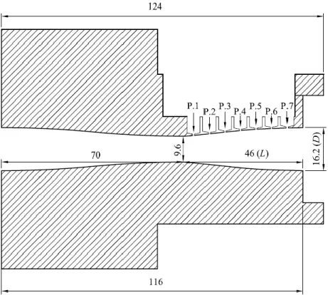
3.3 Convergent-Divergent (C-D) Nozzle
Figure 3.2 shows schematically two convergent-divergent nozzles used in the present study. The interior contour lines of these nozzles are manufactured based upon the method of characteristics (Puckett 1946, Foelsch, 1949) for a design Mach number of 2.0. For the circular convergent-divergent nozzle in Fig 3.2(a), has a throat diameter of 20mm, an exit diameter (D) of 26mm and a nozzle-lip thickness of 2mm at the exit of the nozzle, and has a straight section near the exit of the nozzle. For the two-dimensional convergent-divergent nozzle, the nozzle
CHAPTER 3. Experimental Apparatus 19
has a throat height of 9.6mm, an exit height (D) 16.2mm, and a width 30mm (see Fig. 3.2(b)). And the divergent angles of the nozzles are not constant but total angle in divergent part of circular and 2-dimensional nozzle are about 3.48° and 4.1°, respectively. In the present study, the nozzle pressure ratio NPR (=p0/pa) is defined as the ratio of the pressure (p0) inside the plenum chamber to atmospheric pressure (pa). For the present convergent-divergent nozzles with a design Mach number of 2.0, the correct expansion at the exit of the nozzle is obtained at NPR=7.8.
In the present work, the fully expanded jet Mach number (Mj) will be used to describe the jet expansion condition because the jet Mach number rather than the nozzle pressure ratio has a physical meaning to characterize the supersonic jet.
The jet Mach number is related to the pressure ratio, and is given as follows,
1 1
2 0 1
/
a
j p
M p (3.1) where γ is the specific heat ratio of the gas (γ=1.4).
3.4 Schlieren Optical System
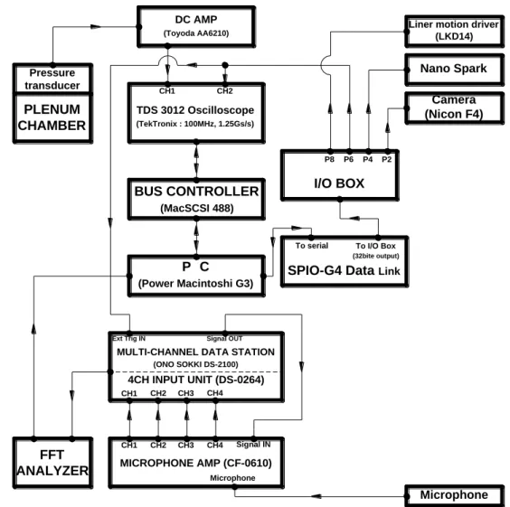
A high quality spark schlieren optical system is employed to visualize the supersonic jet flow, as illustrated in Fig.3.3. The system includes a light source, a collecting lense, pinhole, two concave mirrors and a vertical knife edge. And two types of light sources have been used in the experimental work. The one is nano- spark with a light intensity 10kJ and a duration time of 20ns. And the other one is continuum light source for capturing the shock wave oscillations by high speed video camera. The high speed video camera [Photron FASTCAM SA5] recorded the shock wave movements as the frame rate of 10,000fps for about 1.6 seconds with photo quality of 256×512pixel. The concave mirror has a diameter of 150mm and a focal length of 1000mm.
As shown in Fig.3.4, the output signal from the pressure transducer installed on the plenum chamber is transmitted to a personal computer (PC) through DC
CHAPTER 3. Experimental Apparatus 20
amplifier, oscilloscope and a signal controller, and triggers a nano-spark light source. The remotely triggered light source provides a single spark, and then the light is passed across the test section between two concave mirrors. The schlieren images are recorded on a Nikon D100 digital camera or high speed video camera.
(When the high speed video camera captured the test section, no trigger signal needs to light source.) An open shutter camera obtains the instantaneous images enough to freeze turbulent structures in the supersonic jets.
3.5 Pressure Transducer and Microphone
Calibrated pressure transducers (Kulite XCS-190, XCQ-062) mounted on the nozzle wall at several locations were used to measure and characterize the pressure fluctuation inside the nozzle.
Far-field acoustic measurements are carried out using microphones (Ono Sokki MI-6420) with a diameter of 1/4 inch. It has a sound pressure sensitivity of -24dB±3dB (0dB=1V/Pa), and measures the maximum sound pressure level up to 140dB. The microphones are calibrated using a sound pressure calibrator (Ono Sokki Model). The uncertainty in acoustic measurements is estimated to be less than ±1dB.
The acoustic signals are analyzed by using a 4-channel FFT analyzer (Ono Sokki Model DS0221), as shown in Fig.3.4. A FFT analysis is performed to obtain the power spectra and sound pressure level, providing the spectral data in the range from 0 to 40 kHz. The power spectra are averages of 20 samples, each of which contains 4096 data points.
CHAPTER 3. Experimental Apparatus 21
C-D nozzle Pressure
transducer
Plenum chamber Amplifier
A/D converter
Personal computer
Signal controller
Pressure control valve
Reservoir 3.0MPa,
5m3
Compressor
325
160
5250
1000 4900
Glass wool Supersonic jet
Exit
Directivity arc Microphone r
Figure 3.1 Schematic diagram of experimental facility (unit : mm)
CHAPTER 3. Experimental Apparatus 22
30.6 80.0 49.4
20.0 M30
1.0 2.0
20.0 26.0
Throat
(a) Circular convergent-divergent nozzle
(b) Two-dimensional convergent-divergent nozzle
Figure 3.2 Details of a convergent-divergent nozzle (unit : mm)
CHAPTER 3. Experimental Apparatus 23
Concave mirror
Knife edge
Camera C-D nozzle
Jet flow
Lens Pin hole Collecting lens
Light source
Light
Figure 3.3 Spark schlieren optical system
CHAPTER 3. Experimental Apparatus 24
Pressure transducer
PLENUM CHAMBER
DC AMP
(Toyoda AA6210)
TDS 3012 Oscilloscope
(TekTronix : 100MHz, 1.25Gs/s)
CH1 CH2
BUS CONTROLLER
(MacSCSI 488)
P C
(Power Macintoshi G3)
FFT
ANALYZER MICROPHONE AMP (CF-0610)
CH1 CH2 CH3 CH4
CH1 CH2 CH3 CH4
Microphone Signal IN
4CH INPUT UNIT (DS-0264) MULTI-CHANNEL DATA STATION
(ONO SOKKI DS-2100) Ext Trig IN Signal OUT
P8 P6 P4 P2
I/O BOX
SPIO-G4 Data Link
To serial To I/O Box (32bite output)
Liner motion driver (LKD14)
Nano Spark Camera (Nicon F4)
Microphone
Figure 3.4 Schematic diagram of experimental procedure
25
Chapter 4
Acoustic Characteristics of Transonic Tone and Effect of
Nozzle-Lip Thickness on Transonic Tone in Axisymmetric Nozzle
This chapter discusses the effect of nozzle-lip thickness on the transonic tone in axisymmetric convergent-divergent nozzle and describes a comparison the acoustic characteristics of transonic tone with screech tone according to the nozzle-lip thickness variation. A baffle plate made of an annular metal plate was installed at the nozzle exit to change the nozzle-lip thickness and its diameter was varied. Far-field acoustic measurements are accomplished to obtain the noise spectra of the supersonic jets, which are issued from an axisymmetric supersonic nozzle with a design Mach number of 2.0. The acoustic characteristics of the supersonic jet, such as the transonic tone frequency and amplitude will also be discussed in this chapter using the acoustic measurement results.
4.1 Experimental Conditions
In order to investigate the nozzle-lip thickness effect on the transonic tone, far- field acoustic measurements were made by using a condenser microphone which has 1/4 inch of diameter. The sound pressure measuring locations are schematically shown in Fig. 4.1. Four condenser microphones were located at 12°
CHAPTER 4.Acoustic Characteristics of Transonic Tone and Effect of Nozzle-Lip Thickness on Transonic Tone in Axisymmetric Nozzle 26
interval between 60° and 96°angles from the jet direction along a circular arc of radius 1300mm(r/D=50) away from the exit of the nozzle. The nozzle pressure ratio (NPR) was varied between 1.2 and 2.8, isentropic corresponding to the jet Mach numbers of Mj=0.52 to 1.31. The nozzle pressure ratio applied in this study covers the supersonic jets ranging from choking condition to non-isentropic condition which means shock wave occurs within divergent section in the convergent-divergent nozzle.
An annular baffle plate was installed at the exit of the nozzle to change the nozzle-lip thickness. Details of a baffle plate are shown in Fig. 4.2 and Table 4.1.
The width tb of the baffle plate was varied in the range from 24mm to 76mm. As the simple nozzle has a thickness of 2mm between inner and outer wall at the nozzle exit plane as shown in Fig. 4.1(a), the nozzle lip-thickness ( t ) is given as t=tb+2mm. In the present study, the nozzle-lip thickness is described as t/D non- dimensionalized by the exit diameter of nozzle (D=26mm). Note that t/D=0.1 indicates the basic case without a baffle plate at the nozzle exit.
4.2 Acoustic Characteristics of Transonic Tone
Fig. 4.3 shows a typical noise spectrum of a supersonic jet at low nozzle pressure ratios when a shock wave occurs within the divergent section of convergent- divergent nozzle where r/D=50, θ=96° and NPR=1.8. The spectrum is characterized by three noise components, the turbulent mixing noise, the transonic tones and its harmonics. At first, the detailed acoustic characteristics for the transonic tones will be explained in this chapter.
Fig. 4.4 shows the sound pressure spectra of the jet with NPR=1.2 to 2.8 measured at point of θ=96°, 84°, 72° and 60° degrees. At NPR=1.6 to 2.4, the peak value is observed at about 1kHz and 3kHz. These peak values show the transonic tones and stage1(shown in dotted blue line) and stage2(shown in dotted red line), respectively. It is not exact that the transonic tone exist at NPR1.2 or 1.4 but the case 1.6 of NPR, the transonic tone appear conspicuous and becoming
CHAPTER 4.Acoustic Characteristics of Transonic Tone and Effect of Nozzle-Lip Thickness on Transonic Tone in Axisymmetric Nozzle 27
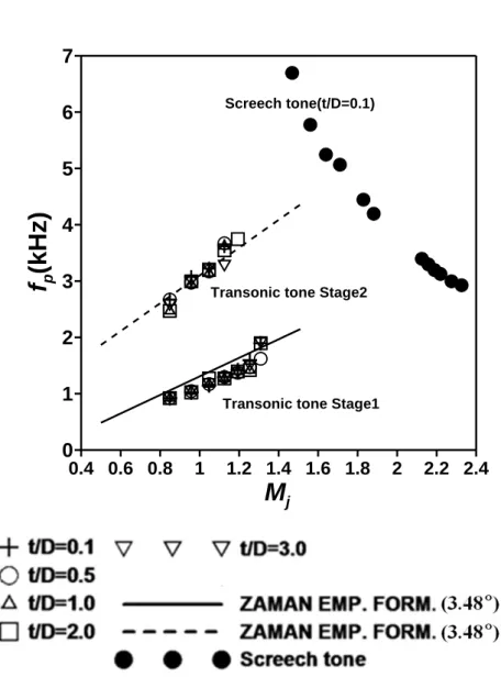
more and more apparent according to increase of NPR and then the stage 2 of the transonic tone level decreases more sharply than stage1's level. After all, no transonic tone can found at more than 2.6 NPR. What's interesting here is that the stage1 of transonic tone level gradually increased at NPR=1.6 to 2.2, and then fell rapidly at NPR=2.4 to 2.6. One more interesting fact is that the transonic tone frequency increased correspond to the increases of NPR. This characteristic is differ from screech tone which, as mentioned earlier, is arising through an acoustic feedback loop between nozzle exit and external shock cell structure. Fig.
4.5 obviously shows the transonic tone in distinction from the screech tone. The frequency data of screech tone had been measured as prior work at same condition with this work(Miyazato, Y. Kweon, Y. H. et al, 2004). In the Fig. 4.5, while the screech tone frequency decrease with NPR increasing, the transonic tone frequency is increased corresponding to NPR. And the result of transonic tone frequency is almost corresponding to the value of the empirical equation proposed by Zaman(Zaman, Dahl, Bencic & Loh 2002) as shown in Fig. 4.5.
The relationships between noise amplitude and Mach number is shown in Fig.
4.6 and Fig. 4.7. The increase or decrease tendency of two noise amplitude with Mach number are similar but the transonic tone has more gradual variation of amplitude with Mach number.
4.3 Effect of nozzle-lip length on Transonic Tone
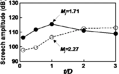
Fig. 4.8 shows the variation of transonic tone amplitude with nozzle-lip thickness.
In Fig. 4.8, it is clearly found that there is little variation, as less than 2 dB, of transonic tone amplitude with the variation of nozzle-lip length. The variation of screech tone amplitude, On the other hand, up to 15dB in Fig. 4.9. This fact is also easily found in Fig. 4.6 and Fig. 4.7. which shows the amplitude variation with Mach number. Overall, the transonic tone emitted at low nozzle pressure ratio relatively. And the transonic tone amplitude and amplitude variation is small compare to screech tone' one. Additionally, the frequency variations are plotted according to nozzle-lip length in Fig. 4.9. At stage 2 of transonic tone, the
CHAPTER 4.Acoustic Characteristics of Transonic Tone and Effect of Nozzle-Lip Thickness on Transonic Tone in Axisymmetric Nozzle 28
frequencies are slightly varied but mostly uniform with nozzle-lip length changing.
Until now acoustic characteristics of transonic tone are discussed by examine the effect of nozzle-lip length on transonic tone with comparing screech tone. The tendency examined earlier, can be interpreted by discussing noise source location.
For example, screech tone occur through feedback loop between nozzle exit and externally located shock cell structure. Therefore the effect of nozzle-lip length is much more than transonic tone which occur in divergent part of convergent- divergent nozzle. The fact that the transonic tone source exist at the inside of nozzle gives a good account for variation of transonic tone frequency according to NPR(or Mach number). That is, as Mach number increase, shock waves moves down stream and then, it is shorter and shorter the noise vibrating region between shock and nozzle exit. Actually, there is close connection between the characteristics of transonic tone and separation shock position in supersonic nozzle. Also it may be explained that the reason why the stage1 decreased rapidly between NPR2.4 and 2.6 in Fig. 4.4 is due to the small angle of half divergence which means expansion angle of divergent part of the nozzle geometry. If the half angle of divergence is sufficiently large, the shock wave moves gradually by NPR increase but the half angle is small, the shock wave moves to downstream rapidly by NPR increase, then, the transonic tone level fall rapidly. The convergent- divergent nozzle used for this chapter, has small of half divergence at nozzle exit.
4.4 Summary
This chapter described the acoustic characteristics and the effect of nozzle-lip length on transonic tone in axisymmetric supersonic nozzle. An annular baffle plate was installed at the nozzle exit to change the nozzle-lip thickness and its diameter was varied. Far-field acoustic measurements were made by using a
CHAPTER 4.Acoustic Characteristics of Transonic Tone and Effect of Nozzle-Lip Thickness on Transonic Tone in Axisymmetric Nozzle 29
condenser microphone. Experiments were accomplished to obtain the noise spectrum of a supersonic jet at low nozzle pressure ratios when a shock wave occurs within the divergent section of convergent-divergent nozzle.
The results obtained clearly show that the transonic tone differently occurs from screech tone in nozzle systems as a source of internal noise. The frequency of transonic tone obtained by experimental work corresponds to Zaman's empirical formula approximately. Considering the results of acoustic characteristics and source location of transonic tone, it is worthy to investigate carefully into relationship between transonic tone and shock wave or flow fluctuation in divergent part of nozzle.
CHAPTER 4.Acoustic Characteristics of Transonic Tone and Effect of Nozzle-Lip Thickness on Transonic Tone in Axisymmetric Nozzle 30
Nozzle exit r/D 96
°
84°
72
°
60
°
Measuring point (microphone)
Jet
Figure 4.1 Microphone locations
CHAPTER 4.Acoustic Characteristics of Transonic Tone and Effect of Nozzle-Lip Thickness on Transonic Tone in Axisymmetric Nozzle 31
D(= 26) 2 Baffle 15
plate
Nozzle tb t
Di Do
(a) Arrangement of a baffle plate (b) Picture
Figure 4.2 Arrangement and picture of a baffle plate (unit : mm)
Table 4.1 Detailed dimensions of baffle plates (unit : mm)
t/D Do Di tb t (=tb+2)
0.1 Simple nozzle (without a baffle plate) 2
1.0 78
30
24 26
2.0 130 50 52
3.0 182 76 78
CHAPTER 4.Acoustic Characteristics of Transonic Tone and Effect of Nozzle-Lip Thickness on Transonic Tone in Axisymmetric Nozzle 32
Figure 4.3 Typical far-field noise spectrum measured at r/D=50 and θ=96°
(NPR= 1.8)
CHAPTER 4.Acoustic Characteristics of Transonic Tone and Effect of Nozzle-Lip Thickness on Transonic Tone in Axisymmetric Nozzle 33
10 100 1000 10000 100000
f (Hz)
45
NPR1.2
55
NPR1.4
65
NPR1.6
70
NPR1.8
70
SP R (d B )
NPR2.0
70
NPR2.270
NPR2.470
NPR2.670
NPR2.8Figure 4.4 (a) Far-field noise spectrum variation with NPR( r/D=50 and θ=96°)
CHAPTER 4.Acoustic Characteristics of Transonic Tone and Effect of Nozzle-Lip Thickness on Transonic Tone in Axisymmetric Nozzle 34
10 100 1000 10000 100000
f(Hz)
45
NPR1.2
55
NPR1.4
65
NPR1.6
70
NPR1.8
70
S P R (d B )
NPR2.0
70 NPR2.2
70 NPR2.4
70 NPR2.6
70 NPR2.8
Figure 4.4 (b) Far-field noise spectrum variation with NPR( r/D=50 and θ=84°)
CHAPTER 4.Acoustic Characteristics of Transonic Tone and Effect of Nozzle-Lip Thickness on Transonic Tone in Axisymmetric Nozzle 35
10 100 1000 10000 100000
f(Hz)
45
NPR1.2
55
NPR1.4
65
NPR1.6
70
NPR1.8
70
S P R (d B )
NPR2.0
70 NPR2.2
70 NPR2.4
70 NPR2.6
70 NPR2.8
Figure 4.4 (c) Far-field noise spectrum variation with NPR( r/D=50 and θ=72°)
CHAPTER 4.Acoustic Characteristics of Transonic Tone and Effect of Nozzle-Lip Thickness on Transonic Tone in Axisymmetric Nozzle 36
10 100 1000 10000 100000
f(Hz)
45
NPR1.2
55
NPR1.4
65
NPR1.6
70
NPR1.8
70
S P R (d B )
NPR2.0
70 NPR2.2
70 NPR2.4
70 NPR2.6
70 NPR2.8
Figure 4.4 (d) Far-field noise spectrum variation with NPR( r/D=50 and θ=60°)
CHAPTER 4.Acoustic Characteristics of Transonic Tone and Effect of Nozzle-Lip Thickness on Transonic Tone in Axisymmetric Nozzle 37
0.4 0.6 0.8 1 1.2 1.4 1.6 1.8 2 2.2 2.4
M
j0 1 2 3 4 5 6 7
f
p(k H z )
Transonic tone Stage1 Transonic tone Stage2
Screech tone(t/D=0.1)
Figure 4.5 Peak frequency distribution of transonic tone and screech tone (r/D=50 and θ=96°)
CHAPTER 4.Acoustic Characteristics of Transonic Tone and Effect of Nozzle-Lip Thickness on Transonic Tone in Axisymmetric Nozzle 38
0.8 1 1.2 1.4
M
j60 80 100 120
A m p li tu d e (d B )
0.1 t/D stage1 0.5 t/D stage1 1 t/D stage1 2 t/D stage1 3 t/D stage1
0.1 t/D stage2 0.5 t/D stage2 1 t/D stage2 2 t/D stage2 3 t/D stage2
Figure 4.6 Relationship between transonic tone amplitude and Mj
( r/D=50 and θ=96°)