Comparison of Synchronization Phenomena in Three Network Topologies
Jun Shiomoto†, Yoko Uwate†, Thomas Ott‡ and Yoshifumi Nishio†
†Dept. of Electrical and Electronic Engineering, Tokushima University, 2-1 Minamijosanjima, Tokushima, 770-8506 Japan
Email:{shiomoto, uwate, nishio}@ee.tokushima-u.ac.jp
‡Dept. Einsiedlerstrasse 31a, 8820 Waedenswil, Switzerland Email:[email protected]
Abstract—In this study, we investigate synchronization phe- nomena of coupled chaotic circuits. The chaotic circuits are combined by resisters on one-dimensional coordinate system. We change the distance between the circuits to adapt the coupling strength. We investigate synchronization phenomena when the distance between the circuits in the group is changed. Also, we measure the phase difference using computer simulations. From the computer simulations, we could make sure of the breakdown of inter-cluster synchronization when the system is changed from the symmetrical system to the asymmetrical system. Additionally, we compare the results of three systems.
I. INTRODUCTION
Synchronization phenomenon is one of the typical phenom- ena observed in nature. Recently, many studies have been investigated synchronization of chaotic circuits [1]∼[5]. It is focused how the differences of the network structure impact on the whole circuits. Additionally, it is applicable to the fields of medical science and biology and so on.
In our research group, we have observed the synchroniza- tion phenomena from symmetrical coupled chaotic circuits and asymmetrical coupled chaotic circuits arranged in one- dimensional coordinate. We used only ladder system. In the ladder system, chaotic circuits are connected to only adjacent circuits. Chaotic circuits were coupled by resister. The number of the circuits was always ten and we investigated symmetrical systems and asymmetrical systems. The distance between the central circuits was fixed. We investigated synchronization phenomena by changing the distance between the circuits. We have made sure of the breakdown of inter-cluster synchro- nization when the system was changed from the symmetrical system to the asymmetrical system [6].
In this study, we use three systems. The systems are ladder system, bridge system and full coupled system. In the full coupled system, the chaotic circuits are connected to all chaotic circuits. In the bridge system, only the circuits in the group are full coupled. Figure 1 shows each system model.
We compare the results of the phase differences in the three systems.
II. CIRCUITMODEL
Figure 2 shows the circuit model. This is a chaotic circuit called Nishi-Inaba circuit [7]∼[8].
(a) Ladder system. (b) Full coupled system.
(c) Bridge system.
Fig. 1. System models.
Fig. 2. Circuit model.
The normalized equations of this circuit are obtained as Eq. (1) by changing the variables as below.
i1=
√C
L1V x; i2= √LL1C
2 V y; v=V z;
r
√C
L1 =α; LL1
2 =β; rd√LL1C
2 =δ;
t=√
L1Cτ; “·” = dτd;
˙
x = αx+z
˙
y = z−f(y)
˙
z = −x−βy
(1)
The value of f(y)is described as Eq. (2).
f(y) = δ 2
(y+1 δ
− y−1
δ )
(2)
- 36 -
IEEE Workshop on Nonlinear Circuit Networks December 12-13, 2014
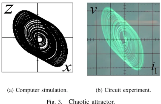
Figure 3 shows the chaotic attractor generated from the circuit by using computer simulation (Fig. 3(a)) and circuit experiment (Fig. 3(b)). For the computer simulation, we set the parameters asα= 0.460,β= 3.0andδ= 470. For the circuit experiment, the parameters are fixed with L1 = 500[mH], L2= 200[mH],C= 0.0153[µF], andrd= 1.46[MΩ].
z
x
(a) Computer simulation. (b) Circuit experiment.
Fig. 3. Chaotic attractor.
In the ladder system, chaotic circuits are connected to only adjacent circuits.
When chaotic circuits are connected to only adjacent cir- cuits, the circuit equations are shown in Eqs. (4)∼(6).
Where the parameter γij represents the coupling strength between the circuits. The value of γij reflects the distance between the circuits in an inverse way, described by the following equation:
γ{i,j}= g
(dij)2. (3)
dijdenotes the Euclidean distance between thei-th circuit and the j-th circuit. The parameter g is coupling coefficient that determines the coupling strengths. In this study, we set the parameter as g= 1.0×10⁻³.
CC1:
˙
x1 = αx1+z1
˙
y1 = z1−f(y1)
˙
z1 = −x1−βy1−γ{1,2}(z1−z2)
(4)
CCn:
˙
xn = αxn+zn
˙
yn = zn−f(yn)
˙
zn = −xn−βyn−γ{n,n−1}(zn−zn−1)
−γ{n,n+1}(zn−zn+1)
(5)
CCN:
˙
xN = αxN +zN
˙
yN = zN−f(yN)
˙
zN = −xN −βyN
−γ{N,N−1}(zN −zN−1)
(6)
In full coupled system, the circuit equation is shown in Eq.
(7).
˙
xi = αxi+zi
˙
yi = zi−f(yi)
˙
zi = −xi−βyi−∑N
j=1γ{i,j}(zi−zj) (i, j= 1,2,· · ·, N)
(7)
In bridge system, the circuit equation is shown in Eq. (8).
This equation shows the case of using ten circuits.
˙
xi = αxi+zi
˙
yi = zi−f(yi)
˙
zi = −xi−βyi−Γ (i= 1,2,· · ·, N)
(8)
CC1∼4:
Γ =γ{n,k}(5·zn−
∑5 k=1
zk) (n= 1,2,3,4)
CC5:
Γ =γ{5,k}(6·z5−
∑6 k=1
zk)
Due to the symmetry of the system, equation for from CC6
toCC10 is omitted.
III. SIMULATIONMETHOD
We use the three systems arranged in one-dimensional co- ordinate system. We use ten circuits in computer simulations.
We divide into the two symmetrical groups, and there are five circuits in one side of the group.
Fig. 4. Network structure.
In the left side and the right side groups, the distances between the circuits are 0.3. The distance between the central circuits is 0.5. The symmetrical network structure is shown in Fig. 5.
Fig. 5. Symmetrical network structure.
We change the distance between the circuits by changing the coupling strength. We define the distances between the circuits in the left side group as d1. In the same way, the
- 37 -
distances between the circuits in the right side group as d2. And we define the distance between the central circuits as dcenter. In this simulation, we fix the values of dcenter and d2, and the value ofd1is changed. The value ofd1is decreased gradually, and the value ofd1is changed from0.3to0.1. The asymmetrical network structure is shown in Fig. 6.
Fig. 6. Asymmetrical network structure.
We measure the phase difference between the circuits using the computer simulation. And we investigate the change in the phase difference when the system is changed from the symmetrical system to the asymmetrical system. Additionally, we compare the results of the three systems.
IV. SIMULATIONRESULT
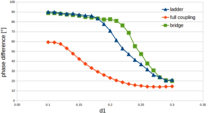
Figure 7 shows the graph of comparison of the results in each system. This figure is focused on only the phase difference of the central circuits.
Fig. 7. Comparison of the results in each system (between the central circuits).
From the simulation result, in the ladder system, the phase difference is increasing gradually. And the central circuits become asynchronous aroundd1= 0.19. In the bridge system, the phase difference is increasing gradually in the same way as ladder system. However the central circuits in the bridge system becomes asynchronous around d1 = 0.22. Although the number of coupling of the bridge system is heavier than the ladder system, the bridge system become faster asynchronous than the ladder system. In the bridge system, only the circuits in the group are full coupled. We consider that the bridge system becomes asynchronous faster than the ladder system, because the coupling in the group becomes stronger. In the
full coupled system, the central circuits do not become asyn- chronous for large number of the coupling.
From this result, we can see that the strength of synchro- nization is not affected by the number of the coupling of the systems.
V. CONCLUSIONS
In this study, we have investigated the synchronization phenomena in coupled chaotic circuits networks. We also investigated the phase difference in the symmetrical network system and the asymmetrical network system. Additionally, we have compared the results of three systems. From the computer simulation, we have confirmed the similar results in all of the system. Additionally, we have obtained very interesting results to compare the central circuits of the three systems.
For the future work, we would like to confirm the same results by using the circuit experiments.
ACKNOWLEDGMENT
This work was partly supported by JSPS Grant-in-Aid for Challenging Exploratory Research 26540127.
REFERENCES
[1] N.F. Rullckov and M.M. Sushchik, “Robustness of Synchronized Chaotic Oscillations,” Int. J. Bifurcation and Chaos, vol. 7, no. 3, pp.
625-643, 1997.
[2] M. Wada, Y. Nishio and A. Ushida, “Analysis of Bifurcation Phenom- ena in Two Chaotic Circuits Coupled by an Inductor,” IEICE Trans.
Fundamentals, vol. E80-A, no. 5, pp. 869-875, 1997.
[3] Y. Nishio and A. Ushida, “Chaotic Wandering and its Analysis in Simple Coupled Chaotic Circuits,” IEICE Trans. Fundamentals, vol. E85-A, no.
1, pp. 248-255, 2002.
[4] G. Abramson, V.M. Kenkre and A.R. Bishop, “Analytic Solutions for Nonlinear Waves in Coupled Reacting Systems,” Physica A: vol. 305, no. 3-4, pp. 427-436, 2002.
[5] I. Belykh, M. Hasler, M. Lauret and H. Nijmeijer, “Synchronization and Graph Topology,” Int. J. Bifurcation and Chaos, vol. 15, no. 11, pp.
3423-3433, 2005.
[6] J. Shiomoto, Y. Uwate, T. Ott and Y. Nishio, “Breakdown of Inter- Cluster Synchronization of Coupled Chaotic Circuits Arranged in One- Dimensional Coordinate,” Proc. NOLTA’14, pp.640-643, Sep. 2014.
[7] R. Stoop, P. Benner and Y. Uwate, “Real-World Existence and Origins of the Spiral Organization of Shrimp-Shaped Domains,” Phys. Rev. Lett., 105, 074102, Aug. 2010.
[8] C. Bonatto and J. A. C. Gallas, “Periodicity Hub and Nested Spirals in the Phase Diagram of a Simple Resistive Circuit,” Phys. Rev. Lett., 101, 054101, Aug. 2008.
- 38 -
![Figure 2 shows the circuit model. This is a chaotic circuit called Nishi-Inaba circuit [7] ∼ [8].](https://thumb-ap.123doks.com/thumbv2/123deta/7315293.2423351/1.892.468.811.352.722/figure-circuit-chaotic-circuit-called-nishi-inaba-circuit.webp)