Title Stability research of river embankment on soft ground usingtraditional reinforcement system in Indonesia( 本文(Fulltext) ) Author(s) SUYUTI Report No.(Doctoral Degree) 博士(工学) 工博甲第562号 Issue Date 2020-03-25 Type 博士論文 Version ETD URL http://hdl.handle.net/20.500.12099/79329 ※この資料の著作権は、各資料の著者・学協会・出版社等に帰属します。
DISSERTATION:
STABILITY RESEARCH OF RIVER EMBANKMENT ON SOFT
GROUND USING TRADITIONAL REINFORCEMENT SYSTEM
IN INDONESIA
インドネシアの軟弱地盤に構築する伝統的補強法を用いた河川
堤防の設計法の提案
SUYUTI
1123812106
MECHANICAL AND CIVIL ENGINEERING DIVISION
FACULTY OF ENGINEERING AND
GRADUATE SCHOOL OF ENGINEERING
GIFU UNIVERSITY, JAPAN
i
List of Contents
List of of contents...i Abstract...iv Chapter 1. Introduction... 1 1.1 Research Background... 11.1.1 Typical natural problem... 1
1.1.2 Technical situation of reinforced soft soil... 7
1.2 Research Objectives...13
References...15
Chapter 2. Proposed Empirical Calculations...16
2.1 Conventional Method of Traditional Reinforcement... 16
2.2 Design Considerations for Calculation... 20
2.2.1 Design reinforcement system...20
2.2.2 Trial construction dataset...20
2.3 Loading Pressure on the Mattress...22
2.3.1 Load pressure of small footing... .22
2.3.2 Load pressure of large footing... 24
2.4 Propose of Empirical Method... 27
2.4.1 Stability criterion... 27
2.4.1.1 Stability criterion for Case 1...27
2.4.1.2 Stability criterion for Case 2...29
2.4.2 Settlement criterion...30
2.4.2.1 Settlement criterion for Case 1...30
2.4.2.2 Settlement criterion for Case 2...30
2.5 Comparison with Finite Element Analysis ...31
2.5.1 Small footing model for mattress... 32
2.5.1.1 Making the geometry of the mattress...33
2.5.1.2 Input soil parameters of material model...34
2.5.1.3 Input parameters of reinforcement models...36
2.5.1.4 Setting of calculation scheme for mattress...38
ii
2.5.2.1 Trial construction dataset...40
2.5.2.2 Making the geometry of the embankment...42
2.5.2.3 Input soil parameters of material model...43
2.5.2.4 Input parameters of material models for reinforcement...46
2.5.2.5 Setting the calculation scheme for the embankment...48
References...50
Chapter 3. Design Criterion of Reinforcement on Thick Soft Clay Foundation of Traditional Construction Method in Indonesia... 52
3.1 Introduction... 52
3.2 Research Objectives... 54
3.3 Theoretical Analyses... 56
3.3.1 Distribution of load pressure...56
3.3.2 The ultimate bearing capacity of reinforced ground... 60
3.3.2.1 Tensile capacity of geo-grid... 60
3.3.2.2 Bearing capacity pile driven in soft clay... 62
3.3.3 Loading pressure on the mattress... 63
3.4 Comparison with Finite Element Analysis... 63
3.5 Design applications... 65
3.4 Summary...73
References...74
Chapter 4. Classical Design Approach of Indonesian Traditional Reinforced Embankment on Soft Clay Ground... 76
4.1 Introduction...76
4.2 Proposed Research Method...79
4.3 Proposed Design Criteria... 81
4.3.1 Design criterion of stability... 81
4.3.1.1 Bearing capacity of reinforced foundation soil... 81
4.3.1.2 Allowable height and safety factor... 87
4.3.2 Settlement criterion... 88
4.3.2.1 Total settlement...88
iii
4.3.2.3 The settlement rate ...95
4.4 Comparison with Finite Element Analysis (F.E.A)... 95
4.4.1 Making geometry of the embankment... 95
4.4.2 Parameters of the material model... 97
4.4.3 Setting calculation scheme for FEA...99
4.5 Results and Discussions...100
4.5.1 Stability criterion...101 4.5.2 Settlement criterion...103 4.6. Summary...107 References...109 Chapter 5. Conclusions ...112 Acknowledgments...114 Appendixes...115
iv
Stability Research of River Embankment on Soft Ground Using Traditional Reinforcement System in Indonesia
Abstract
The ground near seashores or rivers in Indonesia is mostly covered by thick soft soil. In these areas, there are many houses and buildings standing on the soft soil and by the water. To prevent the natural disasters of flooding or big waves, local engineers have to construct tall and long embankments on the soft soil with low bearing capacity and stiffness.
In order to increase the bearing capacity of the soft soil, a traditional reinforcement method using timber piles has been widely used. However, the local design guidelines published by the Ministry of Public Works of Indonesia do not give details of the stability and settlement criteria, but recommend trial construction of a test embankment prior to the real design and construction.
In this study, a simple and practical calculation method using several classical ideas is proposed to obtain the ultimate bearing capacity, the factor of safety and the final settlement for cases with and without reinforcements. The effectiveness of the proposed method is evaluated based on trial embankments conducted in Indonesia and two-dimensional finite element analysis (FEA).
The following are the contents of this research. First of all, the background of this research is introduced, with the natural situation of the target area and technical problems in constructing reasonable countermeasures in Indonesia. After that, the objectives of this research are explained. Secondly, the proposed calculation scheme is explained using the conventional design for the traditional reinforcement system of soft clay. In this section, the required bearing capacity performance is established by the proposed method. Next, new design concepts are adopted within the traditional reinforcement system on thick soft clay using the proposed calculations. The proposed design is applied to determine the bearing capacity criterion, the height of the embankment and the settlement respectively.
It is found that the results from the proposed method can reproduce the bearing capacity and settlement of trial embankments qualitatively. In order to satisfy this research, it is proposed to use a small footing on a mattress overlying soft clay ground supported by timber piles. Then the calculation scheme is provided using an empirical method to establish a reasonable design rule for the required stability and settlement criteria for the embankment. In order to calculate the design criteria ofthe embankment for the traditional reinforcement, elastic and plastic material models are selected in the two-dimensional FEA.
Finally, the results of the empirical calculation and the FEA results are compared with the monitored data from a trial construction. Through these results, the proposed method is demonstrated to be very useful for Indonesian local engineers in charge of the design and construction of embankments on soft clay ground.
Keywords: Design criterion, factor of safety, embankment, soft clay, traditional
1 Chapter 1. Introduction
1.1 Research Background
Flooding and wave attacks are common natural hazards that occuring Indonesia. People living around the seashore or along river banks have to construct high river dikes on soft soils to reduce the damage. However, river dikes usually have problems, mainly centred on natural and technical situations.
1.1.1 Typical natural problems
The typical natural situations in Indonesia are thick soft soils, floods, earthquakes, and wave attacks from seashores or rivers. According to the Ministry of Public Works, about 2,150 floods were recorded from October 1st, 2009 to February 28th, 2015 [1] and 1,566 of these occurred in the eastern parts of Sumatra, northern parts of Java, and southern parts of Kalimantan. Satibi (2009) studied the soft soil areas for all the islands of Indonesia. He plotted these areas in green as shown in the map [2]. The number of floods and the areas of soft soil in the islands of Sumatra, Java and Kalimantan are shown in Figure 1.1.
Figure 1.1 Numbers of floods and areas of soft soil in Indonesia [1, 2] 1,020
239
Java 307
2
Floods and big sea waves are two types of natural hazards that frequently occur in all the Indonesian islands. These hazards have led to severe damage to the residential areas located along the coast as well as along the dikes of rivers. It is impossible to stop these natural hazards, but the local government can apply appropriate technologies in constructing dikes to mitigate the severe damage they can cause.
For this study, two cases of river dikes were used to explain the background, namely the dikes along the Tembilahan and Siak Rivers in Sumatra [3, 4].
In the case of Tembilahan River, the dike was built on soft soil to support the construction of a main access road for the local people in the sub-district.However, the dike collapsed due to the condition of the soil and frequent heavy rainfall, as shown in Figure 1.2 [3].
3
A deep borehole sampling was conducted by the local government at two different points around the collapsed dike. These samples were used for triaxial compression, consolidation and Atterberg limit tests to investigate the soil properties. The results obtained are listed in Table 1.1 [3].
Table 1.1 Soil properties at the Tembilahan River
Depth (m) Soil properties Remark
γs (kN/m3) cu (kPa) PI (%) ϕs (o )
0.0~6.0 14.8 18 52 3 Soft clay-1
6.0 ~ 21.0 16.0 10 83 3 Very soft clay-2
21.0 ~ 23.0 16.8 25 22 10 Mediumclay
23.0 ~ 30.0 17.2 5 - 30 Sand
30.0 ~ 45.0 17.5 23 33 6 Stiff
Table 1.1 shows the effect of the change of depth on the undrained cohesion of soil
cu, the plasticity index PI and the angle of internal friction. When the plasticity index PI is
more than 22%, the angle of internal friction of the soil ϕs is very small at any depth of the
clay layer. These soil layers include very soft clay to soft clay consistencies, with the undrained cohesion cu less than 25 kN/m2 [5].
Moreover, the local government also conducteda field investigation using a Standard Penetration Test (SPT). The results obtained are presented in Table 1.2 [3].
This river dike was reconstructed where the old dike had collapsed, over an area 300 m long and 53 m wide. The construction design adopted was a concrete plate bridge supported byconcrete piles.
4
Table 1.2 The N-SPT tests results at Tembilahan River dike
Depth (m) N-SPT Remark
0.0~6.0 1 Softsoil
6.0 ~ 21.0 1 ~ 3 Very soft soil
21.0 ~ 23.0 15 ~ 27 Medium
23.0 ~ 30.0 18 ~ 21 Sand
30.0 ~ 45.0 > 43 Stiff
Figure 1.3 Cross-section of the typical design of a concrete plate bridge [3] Plate bridge ( t = 25cm) Sidewalk Concrete beam Concrete piles d = 600 mm, L ≈ 32 m s = 2.0 m s = 2.0 m Flood level Normal level Soil dike failure Original ground
Asphalt
Old dike construction
Not to scale Medium clay
to sand layer
Dike before collapse
Soft soil ground: cu, ϕs, γs (N-SPT = 1 ~ 3) - 21 m (N-SPT = 15 ~ 27) - 32 m Stiff layer (N-SPT > 43) ± 0.0 - 27 m Sand to stiff (N-SPT 18 ~ 21)
5
Figure 1.3 shows the typical design of the concrete plate bridge constructed on the Tembilahan River dike. The concrete pile installation was arranged in as quare pattern with a pile diameter d of 600 mm, and pile spacing s of 2 m perpendicular to the river dike and 5 m parallel to the dike [3].
In the case of the Siak River dike, the local government recommended the reconstruction of a dike 600 m in length to overcome flood hazards and big wave attacks from the adjacent river. This led to the provision of a design with the height of the dike to be 5m from the ground surface (GS) as shown in Figure 1.4 [4].
Figure 1.4 Cross-sectional design of Siak River dike [4]
Figure 1.4 shows the properties of the soft soil including the unit weight γs of the soil,
undrained cohesion cu and the angle of internal friction ϕs of the soil. The embankment was
designed on soft soil using the traditional reinforcement method involving
(i) installing timber piles to increase the stiffness of the soft soil as the foundation, (ii) laying geo-grid on the timber piles to reinforce the gravel layer,
1 Geo-grid
6 m
Not to scale
River dike area Slope area
4.5 m 13 m
+5 m
+2 m
±0.0 -1m
Installed timber piles
Counterweight (impermeable) Gravel 1.5 Original ground Gravel Depth Hard layer 6 m 4 m 50 cm 50cm 15cm 10 cm Soft soil: cu, ϕs, γs River GS
6
(iii) spreading and compacting gravel on the geo-grid as a mattress to reinforce and distribute the load from the embankment, and
(iv) constructing an embankment on the mattress for the dike.
The Cone Penetration (CPT) and Standard Penetration (SPT) tests were conducted to determine the soil consistency such as cone resistance qnc, and N-SPT down to a depth of
20 m. The results obtained are shown in Table 1.3 [4].
Table 1.3 The CPT and N-SPT tests results at Siak River Depth(m) CPT, qnc
(kg/cm2) N-SPT Remark
0.0~ 2.1 3 ~ 5 1 ~ 4 Soft soil
2.1 ~ 10.2 2 ~ 3 0 ~ 1 Very soft soil
10.2 ~ 12.0 5 ~ 50 2 ~ 7 Soft soil
12.0~ 20.0 50 ~ 250 > 34 Stiff
Triaxial compression and Atterberg limit tests were conducted to determine the properties of the soil. The results obtained are listed in Table 1.4 [4].
Table 1.4 Soil properties at Siak River
Depth (m) Soil properties Remark
γs (kN/m3) cu (kPa) PI (%) ϕs (o )
0.0~2.1 17 22 64.5 3 Soft clay
2.1 ~ 10.2 11.0 9 83.5 7 Very soft clay
10.2 ~ 12.0 15 14 29.5 9 Soft clay
12.0 ~ 20.0 20 0 - 25 Stiff
Table 1.4 shows the results of the plasticity index PI, undrained cohesion cu of 25 kN/m2 and
7
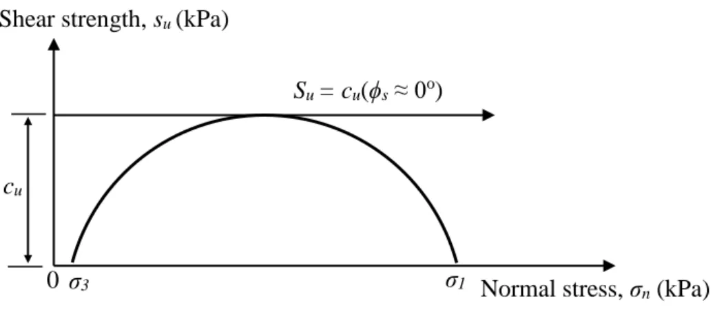
The results of these investigations of dikes for Tembilahan and Siak River showed that they were constructed on soft clay [3, 4]. The consistency of the undrained cohesion cu
with the undrained shear strength of soil su can be expressed based on the Mohr‒Coulomb
failure criterion in Figure 1.5.
Figure 1.5 Mohr‒Coulomb failure criterion of soil using triaxial compression test
Figure 1.5 shows σ1 as the major stress and σ3 the minor stress in the undrained triaxial
compression test. Further calculations proposed in the next sections may involve the use of this undrained shear strength of soft clay su.
1.1.2 Technical situation of reinforced soft soil
To understand the technical situation of the reinforcement of soft soil, a traditional construction method is first introduced. To increase the bearing capacity of soft soil, a traditional reinforcement method using timber piles or bamboo has been widely used for embankments in Indonesia. These piles are called Cerucuk-piles locally in Indonesian.
Indonesian guidelines have been published by the Ministry of Public Works for embankment construction using the traditional reinforcement method [6, 7]. The steps in the
Normal stress, σn (kPa)
Shear strength, su (kPa)
σ3 σ1
Su = cu(ϕs ≈ 0o)
0
8
procedure for embankment construction on soft soil for roads in the guidelines are explained in Figures 1.6 to 1.10 [6. 7].
(1) Cutting the surface of the ground.
Figure 1.6 shows the cutting of the original ground, where it is planned to have the same thickness for the gravel layer Dm and the width of the bottom surface Bb for the embankment.
The groundwater table (GWT) is set as the same as the surface of the ground after cutting (GS).
`
Figure 1.6 Cutting the ground surface
(2) Installing timber piles into soft soil
Figure 1.7 shows the manual installation of timber piles to reinforce the soft soil, arranged in a square pattern. Local material is available to use for piles, which are 6 m long with a diameter d of 8~15 cm.
±0.0
GS (after cutting) GWT
Soft soil: cu, ϕs, γs
Original ground surface (GS)
Depth
Hard layer
Dm
Cutting ground
9 Figure 1.7 Installing timber piles on the soft soil
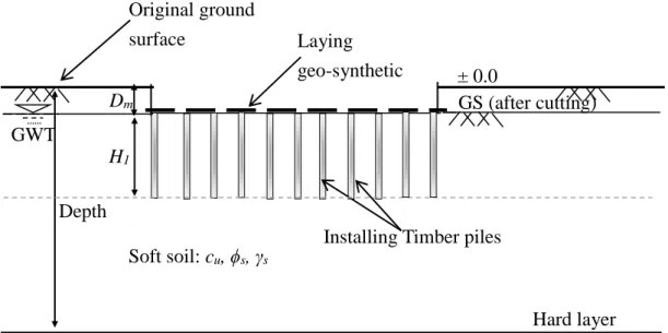
(3) Laying geo-synthetic on top of the timber piles
Figure 1.8 shows the geo-synthetic laid on top of the timber piles and each tips of the geo-synthetic leaves free about 1 m for each side. The geo-synthetic is used to reinforce the gravel layer. There are two options for using geo-synthetics: (i) geo-textile which is for small size gravel, and (ii) geo-grid for large size gravel.
Figure 1.8 Laying geo-synthetic on top of the timber piles
GS (after cutting) GWT
Soft soil: cu, ϕs, γs
Installing Timber piles
H1 Original ground surface Depth Hard layer Dm ± 0.0 Laying geo-synthetic `
Piles installed manually
GS (after cutting) GWT
Soft soil: cu, ϕs, γs
Installing timber piles
H1 s Original ground surface (GS) Depth Hard layer Dm ± 0.0 s d
10 (4) Spreading and compacting gravel
Figure 1.9 shows the spreading and compacting of gravel on the geo-synthetic. The combination of the geo-synthetic and gravel layer for reinforcing the embankment is called the mattress in the guidelines.
Figure 1.9 Spreading and compacting gravel for mattress
(5) Filling up embankment.
Finally, an embankment is constructed on the soft soil using the traditional reinforcement method. These traditional reinforcement materials provide the following dimensions and strength parameters:
(i) Installation of timber piles of length H1 for reinforced soft soil;
(ii) Mattress construction with thickness Dm for distributing load from the embankment,
which is reinforced by geo-synthetic with tensile strength T and angle of friction ϕr
between the mattress and geo-synthetic; and
(iii) The dimensions using the embankment design are height Hb, gradient of slope n,
width at the top of the embankment Ba and width at the bottom of the embankment
Bb as shown in Figure 1.10.
GS (after cutting) GWT
Soft soil: cu, ϕs, γs
Installing Timber piles
H1 Original ground surface Depth Hard layer Dm ± 0.0 Geo-synthetic Spreading and compacting gravel
11
Figure 1.10 Cross-section of embankment on the mattress with underlying soft soil supported by timber piles [6, 7]
Figure 1.10 shows the parameters such as the unit weight of submerged soil layer 1 γs1,the
unit weight of soil layer 2 γs2, the unit weight of water γw, the average width of the
embankment at mid-height B, the unit weight of embankment γb, the gradient of slope of
embankment n, the length of pile H1, the equivalent diameter of the timber pile and the
diameter of a single timber pile d.
These dimensions and parameters of the embankment construction procedure and the stability and settlement criteria are briefly explained in the guidelines.
In respect to the technical situation, the idea of increasing the bearing capacity of soft soil using bamboo piles Qup has been studied by the Ministry of Public Works [8]. In their
final report, full-scale plate loading tests in the field (ASTM-D-1194-1972) were carried out at three sites in West Java (Karawang, Cirebon, and Banjar). The investigation found that the increase of the bearing capacity of soft soil with bamboo pile reinforcements compared with the original soft soil was 315% at the Karawang site, 242% at Cirebon and 215% at Banjar. These experimental results were proposed for a river dike, road and building constructions respectively [8]. However, the bearing capacities obtained can not be applied to other sites, because the condition of soft soil varies at each site.
GS (after cutting) GWT
Embankment
Soft soil-2: cu2, ϕs2, γs2
Installing timber piles Geo-synthetic Mattress Bb Ba n 1 Hb s d Original ground surface Dm H1 Hard layer Depth B Soft soil-1: cu1, ϕs1, γs1
12
In order to determine the appropriate reinforcement of soft soil, the guidelines recommend constructing a full-scale trial embankment and give an outline of the design technique for using a trial embankment for road construction. In these guidelines, the cases of two trial models are explained briefly.
(1) For the first model, a road embankment construction is planned on peat soil with a preloading method without any reinforcement [9]. To determine the stability of the embankment, a stability analysis for a factor of safety is conducted using the limit equilibrium method. This conventional design method is considered to determine the stability of embankment criterion.
(2) For the second trial, a shallow foundation of soft soil using cement and timber piles for road embankment construction was introduced [10]. Generally, with mixed soil‒cement materials for road construction on an embankment, the height of the embankment is limited to 3 m without pile reinforcement. However, for this construction in the guidelines, the height required for the embankment on soft soil is 3 m or more. So, soil‒cement mixing with varying thicknesses and timber or bamboo piles were applied for the required stability and settlement during construction. When the monitored settlement rate is within the rangein the guidelines, the engineer can continue monitoring to check the settlement. Finally, using the monitored data, finite element analysis (FEA) is conducted to simulate the settlement criteria for embankment design. But, it is too difficult for local engineers to conduct the FEA and the recommended process leads to a loss of time and money. Usually, in order for local engineers to establish the design criteria, the currently used design with the traditional method of reinforcement for embankments on soft soil is obtained from a trial construction on site [10].
The traditional reinforcement method for soft soil is still popularly used by Indonesian local engineers and local government. Therefore, an appropriate calculation
13
scheme is required to enable the engineers to design the stability and settlement criteria. In order to prevent natural disasters, a reasonable design rule of construction is required to achieve a good bearing capacity and minimal settlement. However, the criteria for construction to check the stability and the settlement are given without any explanation in the guidelines. The annual settlement rate of an embankment through consolidation is examined to determine whether to design theconstruction using a rigid or a flexible pavement for the road.
The embankment is required to satisfy the performance criteriafor the particular kind of road, so roads constructed on embankments are grouped as (i) a rigid pavement construction for higher importance roads, and (ii) a flexible pavement construction for lower importance roads.
The criterion for settlement of the embankment in the guidelinesis that it must be less than 20 mm/year for higher importance roads and less than 30 mm/year for lower importance roads [8]. The stability of the embankment also requires a factor of safety Fs of 1.40 for higher importance roads and 1.30 for lower importance roads [7].
1.2 Research Objectives
These research objectives are to present a geotechnical solution for the appropriate stability and settlement performance ofa river dike on soft clay ground with the traditional reinforcement system. The aims of the research using an empirical calculation method are to be achieved by taking the following things into consideration:
(1) a mattress constructed on top of the timber piles installation to reinforce and to distribute loads from the embankment, and
(2) an embankment constructed on the mattress, which is supported by timber piles. A reasonable design rule based on geotechnics for design criteria for the traditional
14
reinforcement method can be provided by an empirical calculation scheme. The first study is to identify the load-spreading within the mattress from the surface of the ground, which is calculated by the friction angle of load-spreading. The mattress considered is both unreinforced and reinforced by timber piles, and loaded by a small width of footing [11, 12].
This empirical calculation is applied by using the dataset of the Siak River dike construction. However, the monitored deformation data is not available to compare the design application (see Figure 1.4).
The second study is to propose an empirical calculation scheme using a large width of footing of the embankment.
The dataset from a previous trial construction of an embankment at East Kalimantan, Indonesia, is adopted to evaluate the proposed calculation method in the design application [13]. In order to have the required bearing capacity and settlement for the embankment, a trial embankment is constructed by using the traditional reinforcement method.
The author uses FEA to simulate the stability of the embankment and to check the settlement beneath the embankment for the trial construction dataset mentioned above. However, in the case of trial construction in East Kalimantan, a mattress did not used. The construction procedure of the embankment on soft clay using a mattress for the traditional reinforcement system is required in the guidelines (see Figures 1.6 to 1.10).
Then the simulation result obtained from the FEA is used for comparison with the empirical calculation method. Finally, the stability and settlement criteria of an embankment on soft clay reinforced by geo-textile and timber piles can be presented.
15 References
[1] Ministry of Public Works, Reporting Natural Disasters, Directorate of Water Resources, Indonesia, 2015 (In Indonesian).
[2] Satibi S., Numerical Analysis and Design Criteria of Embankments on Floating Piles, Universitӓt Stuttgart, 2009, p. 1-5.
[3] Ministry of Public Works, Design Construction of River for Protecting Residences and
Infrastructures at Tembilahan District, No.615/SRPD/contract/54/2008, Indonesia,
2008 (In Indonesian).
[4] Ministry of Public Works, Study Countermeasure Damage Against Geotechnical
Construction at Siak River, Final report, Indonesia, 2005(a) (In Indonesian).
[5] Terzaghi K. and Peck R.B., Soil Mechanics in Engineering Practice, John Wiley, 1948, p.299-304.
[6] Ministry of Public Works, Construction Procedures for Timber or Bamboo Pile
Foundation on Soft and Peat Soils, No.020/T/BM/1999, Indonesia, 1999 (In
Indonesian).
[7] Ministry of Public Works, Design and Construction for Road Embankment on Soft Soils,
First Edition–Book 4th, No. Pd- T-10-2002-B, Indonesia, 2002 (In Indonesian).
[8] Ministry of Public Works, Bamboo Pile for Soil Improvement, Final report, Indonesia, 1989 (In Indonesian).
[9] Ministry of Public Works, Design Road Embankment Construction on Peat Soils with
Preloading Method, Indonesia, 2004, p. 1-38 (In Indonesian).
[10] Ministry of Public Works, Soft Soil Shallow Stabilization for Road Embankment
Constructions Using Cement and Timber, Indonesia, 2005(b) (In Indonesian).
[11] Giroud J.P. and Noiray L., Geotextile Reinforced Unpaved Road Design, Journal of The Geotechnical Engineering Division,107(GT9), 1981, p.1233-1254.
[12] Bordeau P.L., Modelling of Membrane Action in aTwo-Layer Reinforced Soil System, Computer and Geotechnics, Elsevier, England, 1989, p.19-36.
[13] Suheriyatna S.L., Imran A.M. and Harianto T.,Full Scale Model Test of Consolidation
Acceleration on Soft Soil Deposition with Combination of Timber Pile and PVD,
16 Chapter 2. Proposed Empirical Calculations
2.1 Conventional Method of Traditional Reinforcement
Local governments have been building river dikes on soft soil using the traditional reinforcement system in Indonesia [1, 2]. The procedure for embankment construction on soft soil has been introduced in the guidelines [3, 4]. The design method for road embankment construction on soft soil using the traditional reinforcement system includes the recommendation by the Ministry of Public Works to perform a trial construction, and that includes monitoring of the settlement at the mattress beneath the embankment [5].
In order to propose an empirical calculcation method using the traditional reinforcement system for embankments, the steps in the procedure for the trial construction for the conventional design of embankments are expressed in Figures 2.1 to 2.5 [3~5].
(1) Cutting the surface of the ground
Figure 2.1 Cutting the ground surface
Cutting ground
GS (after cutting) GWT
Soft soil: su, γs, ϕs
Original ground surface (GS)
Hard layer Depth
17 (2) Installing timber piles into soft soil
Figure 2.2 Installing timber piles in the soft soil
Figure 2.2 shows the situation of pile installation, where H1 is the length of the piles
embedded in the soft soil, s is the spacing of the piles, d is the diameter of the piles, GWT is the groundwater table and GS is the ground surface after cutting.
(3) Laying geo-synthetic on top of the timber piles
Figure 2.3 Laying geo-synthetic on top of the timber piles
s
Laying geo-synthetic
GS (after cutting) GWT
Soft soil: su, γs,ϕs
Installing timber piles
H1
d
Original ground surface
Hard layer Depth
s
Install timber piles
GS (after cutting) GWT
Soft soil: su, γs,ϕs
Installing timber piles
H1
d
Original ground surface
Hard layer Depth
18 (4) Spreading and compacting gravel
Figure 2.4 Spreading and compacting gravel for mattress
(5) Constructing embankment on the mattress
Figure 2.5 Sectional view of trial construction on the mattress with underlying soft soil supported by timber piles [5]
s
Geo-synthetic GS (after cutting) GWT
Soft soil: su, γs,ϕs
Installing timber piles
H1 d Original ground surface (GS) Hard layer Depth Mattress Dm Hb n 1 Settlement plates s Geo-synthetic GS (after cutting) GWT Soft soil: su, γs,ϕs
Installing timber piles
H1 d Original ground surface Hard layer Depth Mattress Dm
19
In the application of the traditional reinforcement method for embankments, the local government has to construct an embankment with the required height of more than 3 m. Usually, soil–cement mixing was applied asa mattress construction, with the wet mixed material spread and compacted on top of the installation of timber piles or bamboo piles before filling the embankment. The role of this mattress is to increase the bearing capacity and to reduce settlement in the trial construction [5]. The dataset from a previous trial construction will be used to simulate the criteria for design of the embankment. The outline of the conventional method is shown in Figure 2.6 [3~5].
Figure 2.6 Conventional method of embankment design on soft soil
In Figure 2.6, when the monitored settlement rate is within the range of the guidelines, the engineer can continue the monitoring to check the settlement. The monitored dataset is used to simulate settlement for designing the real construction of the embankment [5] and the local engineer should use this dataset to conduct FEA to identify the design criteria for the embankment. Finally, the design of embankment can be obtained based on the FEA results
Monitor settlements of trial embankment
Identify design criteria Construct real embankment
Finish Trial embankment
Start
20
and the monitored data. But, it is difficult for local engineers and local government in Indonesia to perform FEA, so the recommended process for construction design leads to a loss of time and money.
Therefore, an empirical calculation using the conventional method of traditional reinforcement for embankment design is proposed in this study by using a trial construction dataset in Indonesia.
2.2 Design Considerations for Calculation 2.2.1 Design reinforcement system
In order to determine the performance of the foundation soil with the traditional reinforcement system for an embankment, two model cases of reinforcement systems are prepared, as listed in Table 2.1 [3, 4].
Table 2.1 Reinforcement system for foundation soil [3, 4] Reinforcement
system Timber pile Geo-synthetic Mattress
Case 1 Without With Gravel
Case 2 With With Gravel
Table 2.1 shows that the mattress used for Case 1 is without timber piles, while Case 2 has foundations where the mattress is supported by timber piles. In Case 2, the position of the pile heads is assumed to be just beneath the mattress. The timber piles are installed without caps to connect between piles.
2.2.2 Trial construction dataset
To simulate the design criteria for the embankment using the empirical method in the calculation scheme, the dataset from a previous trial construction at East Kalimantan in Indonesia is adopted. The trial construction is shown in Figure 2.7 [6, 7].
21
(a) Cross-section of embankment in the trial construction
(b) Timber pile cluster used in the trial construction
Figure 2.7 Cross-section of a trial embankment construction on soft clay ground supported by timber pile cluster [6, 7]
Figure 2.7 (a) shows the trial embankment which was constructed on normally consolidated soft clay. The shear strength of soft clay layer 1 (su1) and soft clay layer 2 (su2) are used to
define the soil parameters for the design considerations. Three timber piles d
Timber pile cluster GWT Hb(Embankment) B Soft clay-1: su1, γs1 Soft clay-2: su2, γs2 n 1 H1 Ba d s Stiff layer Hs (considered depth) Original ground surface (GS) Bb Geo-textile
22
Figure 2.7 (b) shows the timber pile clusters used in the trial construction. A model of a two-dimensional timber pile cluster driven in soft clay is used to calculate the friction and end bearing capacity. The equivalent diameter of the timber pile cluster de is calculated
using two equations.
For friction capacity, the diameter equivalent of pile cluster def is defined (Appendix A) as
d
def =2.5 (2.1)
For the bearing capacity of the tip, the diameter equivalent of the timber pile cluster deb is
defined as
d
deb = 3 (2.2)
where d is the diameter of a single timber pile.
2.3 Loading Pressure on the Mattress
In order to prepare the empirical calculation method for the required stability and settlement criteria, the foundation can be defined intwo strip footing models:
(i) a small strip footing model, which is simplified by using a static load from truck tyres, and
(ii) a large strip footing model, which is modelled from the full embankment.
2.3.1 Load pressure of small footing
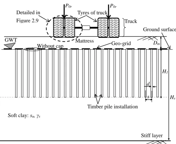
In this model, a foundation is constructed on normally consolidated clay. Gravel or sandy gravel material is used for the mattress, and it is reinforced by geo-grid and timber piles [2]. For mattress construction, we need the thickness, angle of friction and bulk density. Therefore, in the real construction a lightweight roller machine is used for compacting the gravel layers. The loading pressure of a small footing on the mattress construction can be idealised by static loading from tyres, which areassumed to be from a truck’s rear axle P0r.
23
Figure 2.8 Truck tyres loaded on the mattress supported by timber piles
Here, Dm is the thickness of the mattress, H1 is the length of the piles embedded in soft clay, d
is the diameter of the piles, s is the spacing of the piles, Hs is the depth of the soft clays.
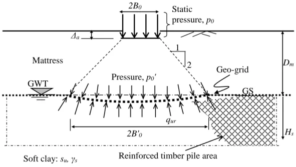
The static load pressure p0 with width footing 2B0 from the mattress surface through the
mattress to the ground surface is set up by a two-dimensional model in the calculation. This is shown in Figure 2.9 [9, 10]. Ground surface GWT Soft clay: su, γs Stiff layer Mattress Geo-grid
Timber pile installation
Dm H1 Tyres of truck Truck Detailed in Figure 2.9 P0r P0r Hs d s Without cap
24
Figure 2.9 Static loading pressure p0 acting on the mattress supported by timber piles
Here, 2B0 is the width of the strip footing for two tyres, 2B'0 the width of the strip footing at
the ground surface, p0 is the static loading pressure, p0' is the load pressure distributed at the
ground surface, qur is the ultimate bearing capacity of the soft clay reinforced with geo-grid
and the bearing capacity of the timber piles driven in soft clay.
To determine the tensile strength capacity of the geo-grid on the soft clay, the vertical deformation ∆a is allowed by load pressure p0 at the mattress surface, as required in the
guidelines [4].
2.3.2 Load pressure of large footing
In order to presentthe proposed empirical calculation method using a two-dimensional model, the load pressure of a large footing of the embankment is applied. The trial construction on the soft clay using the traditional reinforcement system is adopted for the proposed calculation (see Figure 2.7) [6, 7]. Therefore a large footing width Bb of an
embankment for the required design criteria is distinguished as two sections for discussion below.
Reinforced timber pile area Pressure, p0' Mattress Soft clay: su, γs Static pressure, p0 2B0 2B'0 Dm Hs Δa qur GWT 1 2 Geo-grid GS
25
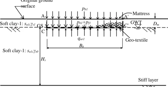
(1) The loading pressure model of the large footing on the gravel layer reinforced with geo-textile (as mattress) is shown in Figure 2.10.
Figure 2.10 Static loading pressure of large footing on the mattress on soft clay
In the figure, the following parameters are defined: the loading pressure on the large footing from embankment pb1, the loading presssure of mattress pf1, the ultimate bearing capacity of
original soft clay qs, the width of the footing at the bottom of the embankment Bb, the
thickness of the mattress Dm and the depth of the soft clay Hs.
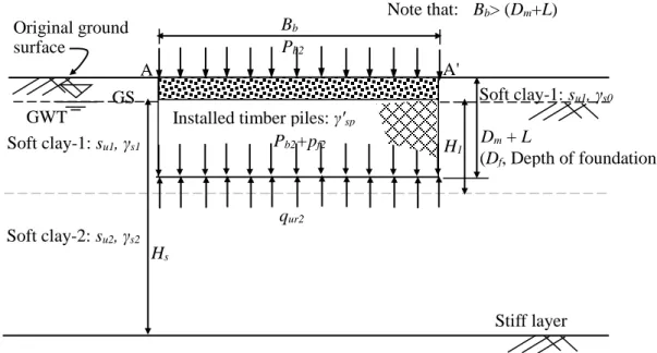
(2) The loading pressure of the large footing on the mattress construction supported by timber piles is shown in Figure 2.11.
GS GWT Soft clay-1: su1,γs1 Bb Dm Original ground surface p b1 qur1 Mattress Geo-textile C' C A' A pb1+pf1 Soft clay-1: su1,γs0 Hs Stiff layer
26
Figure 2.11 Static loading pressure of the large footing on the mattress supported by timber piles
Here, pb2 is the loading pressure of the large footing on the embankment (pb1 = pb2), pf2 is the
loading presssure of the mattress (pf1 = pf2), qur2 is the ultimate bearing capacity of the soft
clay with geo-textile supported by timber piles, Dm is the thickness of the mattress and γm is
the unit weight of the mattress.
The load pressure from the embankment pb2 is supported by a shallow large footing
consisting of timber piles and the mattress. It is assumed that the area reinforced with timber piles and the mattress behaves as a rigid block.
Therefore, the traditional reinforcement system for soft clay can be analysed using the Terzaghi‒Peck classical formula, which is prepared with the large footing width Bb. This
classical formula refers toa shallow foundation by the ratio of (Dm+L) / Bb < 1.0, where
(Dm+L) is the depth of the shallow foundation soil [11, 12].
Soft clay-2: su2, γs2
Soft clay-1: su1, γs1 Dm + L
GWT
GS
Bb
Installed timber piles: γ'sp Original ground surface Note that: Bb> (Dm+L) Pb2 qur2 A A' H1 Pb2+pf2 (Df, Depth of foundation) Soft clay-1: su1, γs0 Stiff layer Hs
27 2.4 Proposed Empirical Method
This chapter addresses an empirical calculation method to design the criteria of an embankment on soft clay ground using the traditional reinforcement system (see Table 2.1). However, the empirical calculation method of a small width footing’s stability criterion will be presented in Chapter 3. The design of the stability and settlement criteria is presented through two cases respectively.
2.4.1 Stability criterion
2.4.1.1 Stability criterion for Case 1
The model of Case 1 is an embankment on a mattress. The design criterion of the embankment on the mattress is required as [13, 14]
1 1
1 f ur
b p q
p + (2.3)
Where qur1 is the ultimate bearing capacity of soft clay, pb1 is the load pressure distributed at
the ground surface and pf1 is the mattress pressure as the foundation.
Hence, the ultimate bearing capacity of soft clay qur1 is provided with the tensile strength of
the geo-textile, and can be defined as (see Figure 2.10) [14, 15]
2 1
1
q
q
q
ur=
+
(2.4)
where q1 is the bearing capacity of the soft clay, q2 is the capacity of the geo-textile laid at
the ground.
The ultimate bearing capacity of the soft soil q1 for a large strip footing width Bb is usually
calculated by [12, 14]
D N B N N c q u c s f q 2 b s1 1 0 1 1 = + + (2.5)where Nc,Nq, Nγ are the soil bearing capacity factors, defined as
) 2 45 ( tan ) tan exp( 2 o s s q N =
+
(2.6a) s q c N N =( −1)cot
(2.6b)28 s
q
N
N =2( +1)tan
(2.6c)where Df is the depth of the footing, ϕs is the the internal friction of the soil, γs0 is the unit
weight of soft soil at the top of the ground watertable, andγs1 is the unit weight of saturated
soft soil layer 1.
In this case, the angle of internal friction of soft soil ϕs is very small, so ϕs is assumed to be
zero. The factors for the soft soil bearing capacity obtained are Nc of 5.14, Nq of 1.0 and Nγ
of zero [14].
The bearing capacity factors in Equation (2.5) for the ultimate bearing capacity of the soil are given by f s c u N D s q1= 1 +
0 (2.7)In this soft clay, the undrained shear strength of soft clay-1 su1 is used in the calculation (see
Figure 2.10), where γs0 is the unit weight of soft clay-1 above the groundwater level, and Df
is the depth of the foundation.
The tensile strength capacity of the geo-textile q2 per unit meter for width footing Bb is
predicted as [15, 17] b r gt B T q2 = 2 sin
(2.8)where ϕr is the interface friction between the geo-textile and the mattress at both points C-C'
in Figure 2.10.
The width at the bottom of the embankment Bb is defined as (see Figure 2.7)
b a
b
B
nH
29
2.4.1.2 Stability criterion for Case 2
The model of Case 2 is an embankment on a mattress supported by timber piles, for which the design criterion is [13, 14]
2 2 2 f ur b p q p + (2.10) 2 1 b b p p = (2.11)
The loading pressures of the embankment pb2 and the soil foundation of the mattress pf2 at the
ground surface can be derived as
(
D L)
H p
pb2 + f2 =
b b +
m m +
'sp (2.12)where γ'sp is the (bulk) unit weight of the soft clay with piles, γm is the unit weight of the
mattress, and Dm is the thickness of the mattress (Dm ≈ Df).
The ultimate bearing capacity of the mattress supported by timber piles at the width points A-A' qur2 in Figure 2.11 is
L D
N c
qur2 = u2 c+
s0 m +
's1 (2.13)The effective unit weight of soft clay-1 γ'sp after installing piles is
(
)
p e
s p(
e)
psp n d s n d
' = 1− 2 /4 2 '1+ 2/4 (2.14)
where np is the number of timber piles driven per meter square (np = 1.0), γp is the unit weight
30 2.4. 2 Settlement criterion
2.4.2.1 Settlement criterion for Case 1
The model of Case 1 is an embankment on a mattress construction. The total settlement of the ground surface beneath the embankment on the mattress Δhr1 is defined as
[16]
0
1 h h
hr = em +
(2.15)
where δhem is the deformation of the embankment on the mattress layer with geo-textile, and
δh0 is the primary settlement by consolidation of the soft clay beneath the mattress.
The calculation of the settlement rate of the soft clay ∆ht by consolidation is considered with
the time period t [4, 16]:
1 0 z m t h h U h = + (2.16)
where Uz1 is the degree of consolidation of soft clay-1.
2.4.2.2 Settlement criterion for Case 2
The model of Case 2 is an embankment on a mattress with geo-textile supported by timber piles. The total settlement of the soft clay surface beneath the embankment on the mattress supported by timber piles Δhr2 is defined as
2 1
2 h h h
hr = m + +
(2.17)
where δhm is the deformation of the mattress. By the mattress layer is assumed as a rigid
footing, it is not allowed vertical deformation (δhm≈ 0) (see Figure 2.11). In which, δh1 is the
elastic deformation of the timber piles and δh2 is the primary settlement by consolidation of
31 δhm GS σbm1 σ'v02+Δσv L= H1 H1/3 2/3(H1) GWT B' Stiff layer Soft clay-2 δh1 δh2 Timber piles 2 1 H2 H2/4 B' H1/6 H2/4 H1/3+H2/2 +B' 5 L /6+H 2 /2 σbm1 H1/6 H2/2-H1/6 Original ground surface (GS)
The definitions of these parameters for the embankment of Case 2 are expressed in Figure 2.12.
Figure 2.12 Definition of parameters for considered design of settlement [17]
The settlement rate of the soft clay by consolidation (Δht*) can be given as 2 2 1 * z t h h U h = + (2.18)
where Uz2 is the degree of consolidation of soft clay-2 in Case 2.
2.5 Comparison with Finite Element Analysis
In order to compare the results from the empirical calculation method for the embankment using the traditional reinforcement method, two-dimensional FEA is used to simulate the design criteria for embankments with the two kinds of reinforcement: (i) a
32
mattress construction as a small footing by tyres loading, and (ii) a mattress construction loaded by a large footing for the full embankment .
2.5.1 Small footing model for mattress
A mattress construction on soft clay ground reinforced with timber piles is modelled as small strip footing width 2B0 with pressure p0 from truck tyres. To determine the soil stress
beneath the mattress, FEA is carried out on the loading pressure p0. The calculation steps for
the mattress are shown in Figure 2.13 [18].
Figure 2.13 Outline of calculation steps for mattress using FEA
Figure 2.13 shows the flow ofcalculations for the embankment at the Siak River dike adopted to apply FEA for the stability criterion (see Figure 1.4). The dimensions and parameters of the geo-grid and timber piles for reinforced soft clay shown in Figure1.4 are used in the calculations.
Adopt designed embankment (Siak River dike)
Make geometry of mattress on soft clay ground Input parameter dataset of the material model Make calculation using plastic analysis Check calculation results of soil stresses beneath mattress
Start
33
2.5.1.1 Making the geometry of the mattress
In order to simulate the mattress construction on the soft clay ground with FEA, the geometry of the mattress is represented by a thickness Dm of 0.80 m and a depth of soft clays of about
12 m, as modelled in Figure 2.14 [18].
Figure 2.14 Geometry of mattress construction model
Figure 2.14 shows the geometry of the mattress model created by the two-dimensional symmetric condition with an x,y coordinate system, in which x is the horizontal and y is the vertical coordinate. The boundary conditions of the mattress construction are set up by x and y fixed pon the bottom boundary and x fixed on the side boundary.
The geo-grid laid on top of the timber piles at the ground surface beneath the mattress construction is expressed in Figure 2.15.
(150, 119.2) (150, 108) (150, 120) y x (0, 0) (15, 120) (150, 0) (Unit : m) (-150, 120) (-150, 0) (-15, 120) Soft clays Pressure p0 Not to scale (-150, 119.2) Mattress Footing 2B0 (-150, 108)
34
Figure2.15 Modelled half-width strip footing on the mattress
2.5.1.2 Input soil parameters of material model
The soft clay parameters for the finite element simulation referto the final design report of the embankment at Siak River [2]. To calculate the soil stresses at any point beneath the mattress construction, an analysis of undrained soil is modelled in a plastic analysis using the Mohr‒Coulomb (MC) model in the FEA. The soft clay properties at the Tembilahan River and Siak River dikes are considered in this section, following Chapter 1 (see Table 1.1 and Table 1.4).
To simulate the soil’s elastic and plastic behaviour in the FEA, the Mohr‒Coulomb (MC) model is used for all the soil layers of the ground. The MC model involves five parameters: the Young’s modulus of soil Es, Poisson’s ratio υs for soil elasticity, angle of
internal friction ϕs, cohesion c for soil plasticity, and angle of dilatancy ψ.
The input parameters of the soils and of the gravel material for the MC model used in FEA are listed in Table 2.2 and Table 2.3.
Ground surface Geo-grid Timber piles B0 GWT p0 (150, 117) for L = 3m Soft clays
35
Table 2.2 The parameters of soft clay ground for the MC model used in the FEA [2, 3]
Soil layers: Soft clay Medium
clay Stiff layer
Depth (m) Unit 0 – 6 6 – 21 21 – 30 > 30
Material type Undrained Undrained Undrained Undrained
-Unsaturated γunsat (kN/m3) 13.6 14.1 15.2 13
-Saturated γsat (kN/m3) 14.8 16 16.8 14.8
Permeability kx (m/day) 9E-05 9E-05 9E-05 9E-05
Permeability ky (m/day) 9E-05 9E-05 9E-05 9E-05
Cohesion c (kN/m2 ) 10 18 25 5
Internal friction ϕ (o ) 3 3 10 30
Young’s modulus Es (kN/m2) 2,500 2,500 3,000 3,500
Poisson’s ratio υs - 0.35 0.35 0.35 0.30
Dilatancy ψ (o ) 0 0 0 0
Table 2.3 The parameters of gravel for the MC model used in the FEA [19]
Gravel material Unit Value
-Unsaturated γunsat (kN/m3) 19 -Saturated γsat (kN/m3) 20.5 Permeability kx (m/day) 1 Permeability ky (m/day) 1 Cohesion c (kN/m2 ) 1 Internal friction ϕ (o ) 46 Young’s modulus E (kN/m2) 4,000 Poisson’s ratio υ - 0.35 Dilatancy ψ (o ) 16
36
2.5.1.3 Input parameters of reinforcement models
There are two kinds of reinforcement for the traditional system. The Siak River dike is built on soft clay using geo-grid reinforcement and supported by ordinary timber piles (see Figure 2.15) [2]. These material reinforcements are explained respectively below.
(1) Geo-grid reinforcement
In the model of the geo-grid used to reinforce the gravel layer as amattress (see Figure 2.15), the tensile strength Tgg and strain εgg properties of the geo-grid are associated to determine the
axial stiffness parameter EggAgg, which is defined as [20]
(
gg)
gggg
ggA T
E = 100 /
(2.19)(2) Timber pile reinforcement
The timber piles are installed in soft clay to support the gravel layer. In this section, the timber piles are applied as an anchor type to make the model in the software an elasto-plastic material.
There are four parameters for pile modelling: the axial stiffness for timber piles EopAop,
spacing of piles s, maximum force of pile compression Fcomp, and maximum force of pile
tension Ftens. These are explained respectively as follows.
(i) For the parameter of the timber pile material’s axial stiffness EpAp, it is defined that the
constant spring of timber pile k in the soft clay ground can be written as the following equation [21]: 1 H A Eop op
k =
(2.20)37 Then the axial stiffness EpAp is given by
1
kH A
Ep p = (2.21)
where H1 is the length of the timber piles embedded in the soft clay.
The image of the constant spring of timber pile k is shown in Figure 2.16.
Figure 2.16 Model of constant spring k for timber pile in the soil [21]
The constant spring k can be defined as
p op F k
= (2.22)in which δp is the allowed deformation of the timber, and d is the diameter of the timber
pile.
By assuming the allowable force Fp loaded on the timber pile, force Fp will be mobilised
by allowing a vertical deformation of pile δp in the amount [21]
10
d p =
38
Then the allowable load capacity of the timber pile driven in soft clay Fop can be defined as
0
F P
F u
op = (2.24)
where Fo is the safety factor for estimating the allowable load capacity of a floating timber
pile driven in soft clay.
The ultimate load-bearing capacity of timber pile Pu driven in soft clay is calculated as
written in the equations in Appendix B [11].
(ii) The spacing of piles is according to the installation method of the construction procedure published in the guidelines (see Figure 1.7).
(iii) The maximum force of pile compression Fcomp is assumed to be equal to the ultimate
load-bearing capacity of timber pile Pu. The detailed equations of the calculation can be
found in Appendix B.
(iv) For the maximum force of pile tension Ftens [11], the ultimate load-bearing capacity of
timber pile Pu driven in soft clay is calculated. The detailed equations for this calculation are
given in Appendix C.
2.5.1.4 Setting of calculation scheme for mattress
In the calculation scheme of the FEA, the initial conditions are calculated with the initial pore water pressure, which comes from the water level at the ground surface. For drainage conditions, the ground surface is drained and the other boundaries of the two vertical sides are undrained.
The calculation steps start by creating a model of the ground, laying the model of the geo-textile on the ground, installing piles into the soft clay, and so making the model of the mattress and calculating the soils tresses (see Figures 2.14 and 2.15).
39
To calculate the soil stresses beneath the mattress, a plastic analysis is provided in FEA and is set up as below.
(1) making the ground model, placing the geo-grid, constructing a mattress, selecting the plastic analysis and mattress pressure p0 of a small strip footing width 2B0 (see
Figure 2.14).
(2) making the ground model, creating the timber pile installation, placing the geo-grid, constructing a mattress, selecting the plastic analysis and load from mattress pressure p0 with the strip footing (see Figure 2.15).
2.5.2 Large footing model for embankment
A mattress construction on soft clay ground reinforced by timber piles is modelled with a large strip footing as the full embankment. The calculation steps using FEA for the embankment are shown in Figure 2.17.
Figure 2.17 Outline of calculation steps using FEA for embankment
Usetrial construction data in Indonesia [6, 7] (at East Kalimantan)
Represent trial construction stages Make geometry of embankment Input parameters of the material
Check calculation results for design criteria
Start
40
2.5.2.1 Trial construction dataset
To prepare the parameters of the soil models for simulation in the FEA, the dataset of the trial construction of the embankment at East Kalimantan (see Figure 2.7) is adopted. The obtained properties of the soft clay and embankment are listed in Tables 2.4 and 2.5 [4, 6, 7].
Table 2.4 The parameters of soft clay ground [6, 7]
Depth (m) Unit weight (kN/m3) Cohesion cu (kN/m2) Angle of friction ϕs ( o) Permeability (m/day) Remark Unsaturated γunsat Saturated γsat kx ky
0 – 4 12 14.5 10 5 1.38E-03 6.89E-04 Soft
clay-1
4 – 6 12 14.5 12 8 1.38E-03 6.89E-04 Soft
clay-2
6 – 12 13 15 20 12 1.38E-03 6.89E-04 Soft
clay-3
12 – 18 15 16 25 14 1.38E-03 6.89E-04 Soft
clay-4
18 – 25 16 18 30 16.5 1.38E-03 6.89E-04 Silty sand
> 25 16 18 30 16.5 1.38E-03 6.89E-04 Hard layer
Table 2.5 The soil parameters of the embankment [4, 7]
Unit weight (kN/m3) Cohesion Friction Permeability Unsaturated, γunsat Saturated, γsat cu (kN/m2) ϕb( o) kx (m/day) ky (m/day)
19 20 1 33 2 1
For this trial embankment construction, it was reported that timber pile clusters were installed in the soft clay before laying the geo-textile (see Figure 2.7). The axial stiffness of the timber pile clusters EpcApc will be explained below.
The local government conducted a trial construction at East Kalimantan by working with embankments 20 m long and 30 m wide for Case 1 and Case 2. The trial embankments of the two cases were monitored for 98 days and vertical deformation was reported at the
41
centreline of the ground beneath the embankment [6,7]. The details of the two cases are shown in Figures 2.18 and 2.19.
(1) Case 1 is an embankment on soft clay reinforced by geo-textile.
Figure 2.18 Construction stages of trial embankment for Case 1 [6, 7]
(2) For Case 2, an embankment on soft clay reinforced with geo-textile and supported by timber pile clusters is shown in Figure 2.19.
Figure 2.19 Construction stages of trial embankment for Case 2 [6, 7] Height, Hb (m) Time, t (day) 14 52 65 98 0 Embankment 1st stage 2nd stage 3rd stage 3m 4.5m 1.5m
(38 days) (13 days) (33 days) (14 days) Duration (days) Height, Hb (m) Time, t (day) 14 52 65 98 0 Embankment 1st stage 2nd stage 3rd stage 3m 4.5m 1.5m
(38 days) (13 days) (33 days) (14 days)
42
The reinforcement parameters of the traditional system in the finite element simulation are listed in Table 2.6 [7].
Table 2.6 The parameters of traditional reinforcement in the trial construction [6, 7] Trial
construction
Geo-textile
Tgt (kN/m)
Timber pile cluster
Remark Diameter
de (cm)
Length
H1 (m)
Case 1 55 - - Without piles
Case 2 55 25 (d =10cm) 6 With timber piles
Table 2.6 shows the obtained diameter equivalent of timber pile clusters using Eq.2.2 (see Figure 2.7(b).
2.5.2.2 Making the geometry of the embankment
In order to make the FEA simulation of the design embankment on the soft clay ground, the geometry of the embankment is modelled as shown in Figure 2.20.
Figure 2.20 Geometry of embankment model on soft clay ground
(150, 120) y x (0, 0) (15, 120) (8.25, 124.5) (150, 0) (Unit : m) (-150, 120) (-150, 0) (-15, 120) (-8.25, 120)
Soft clay ground
Embankment
43
The geometry of the embankment models on soft clay ground created by the two-dimensional symmetric construction with coordinate system (x,y) for the two cases is shown respectively in Figure 2.21 and Figure 2.22.
Figure 2.21 Modelled embankment construction for Case 1
Figure 2.22 Modelled embankment construction with timber piles for Case 2
Figure 2.21 shows the boundary conditions of the embankment, where x and y are fixed on the bottom boundary and x is fixed on the side boundary for the geo-textile laid on the ground surface, and both of the toes are opened with length 2.5 m for the two cases.
2.5.2.3 Input soil parameters of material model
In order to make FEA simulations of the design criteria for the embankments, the soil parameters obtained from the trial construction dataare adopted (see Table 2.3 and Table 2.4). The parameters of the soft clay ground and embankment were reported for the Mohr‒Coulomb failure criterion (MC) [6, 7]. Thus, this simulation is represented by two soil
(15, 120) Geotextile (2.5m free) Embankment Timber piles Ground surface (15, 120) (8.25, 124.5) Geo-textile (2.5m free) Embankment Soft clay Ground surface
44 models as explained respectively.
(1) Modified Cam-Clay model for soft-to-medium clay layers
The Modified Cam-Clay (MCC) model is selected for normally consolidated soft clays. The material for the Modified Cam-Clay model consists of five parameters: the Cam- Clay compression index λ, Cam-Clay swelling index κ, critical state line M, Poisson’s ratio
υur and initial void ratio e0 [22].
The compression index λ is defined as [22]
PI 0058 . 0 =
(2.25)The plasticity index PI (in percent) for all of the soil is predicted by [23]
34 . 13 ) 1 ( 3 . 102 0 + + = e C PI c (2.26)
where Cc is the consolidation compression index of the soil.
The swelling index κ can be calculated by the next equation [22]:
0 . 8 0 . 3
(2.27)For the initial compression stress states, the slope of the critical state line M is defined as [22, 23] (3 sin ) sin 6 s s M − = (2.28)
where ϕs is the angle of the internal friction of the soil from the triaxial compression test.
In soft clays, the angle of dilatancy parameter ψ for the MCC model is almost zero [18]. The results obtained from the soil sample for the input parameters of soft clay ground are listed in Table 2.7.
45
Table 2.7. Input soft clay ground parameters for MCC model used in FEA
Soil layers Soft clay Medium clay
Depth (m) Unit 0 – 4 4 – 6 6 – 12 12 – 18 18 – 25
Material type Drained Drained Drained Drained Drained
Soil unit weight: [6, 7]
Unsaturated γunsat (kN/m3) 12 12 13 15 16
Saturated γsat (kN/m3) 14.5 14.5 15 16 18
Permeability:
Permeability kx (m/day) 1.38E-03 1.38E-03 1.38E-03 1.38E-03 1.38E-03
Permeability ky (m/day) 6.89E-04 6.89E-04 6.89E-04 6.89E-04 6.89E-04
Initial void ratio einit - 2.2 2.2 2 1.8 1.5
Coef. consol. Cc - 0.9 0.9 0.85 0.6 0.4 Plasticity PI (%) 42.11 42.11 42.33 35.26 29.7 Compression λ [22] - 0.525 0.525 0.496 0.384 0.290 Swelling κ - 0.088 0.088 0.082 0.069 0.057 Poisson’s ratio of unloading-reloading υur [18] - 0.15 0.15 0.15 0.15 0.15
Slope of critical state
line M [22] - 0.179 0.292 0.447 0.772 1.199
Cohesion c [6, 7] (kN/m2 ) 10 12 20 25 30
Internal friction ϕ (o ) 5 8 12 14 16.5
Dilatancy ψ [18] (o ) 0 0 0 0 0
(2) Mohr‒Coulomb model for hard layer and embankment
For elastic perfectly-plastic soil behaviour, the Mohr‒Coulomb (MC) model is used for the hard layer and embankment. The MC model involves five parameters: Young’s modulus E, Poisson’s ratio υ, angle of friction ϕ, cohesion c and angle of dilatancy ψ.
The results obtained for the hard layer and embankment for the input soil parameters are listed in Table 2.8.
![Figure 1.3 Cross-section of the typical design of a concrete plate bridge [3]](https://thumb-ap.123doks.com/thumbv2/123deta/10088387.1489396/10.892.133.782.392.1095/figure-cross-section-typical-design-concrete-plate-bridge.webp)
![Figure 1.10 Cross-section of embankment on the mattress with underlying soft soil supported by timber piles [6, 7]](https://thumb-ap.123doks.com/thumbv2/123deta/10088387.1489396/17.892.155.717.125.479/figure-cross-section-embankment-mattress-underlying-supported-timber.webp)
![Figure 2.5 Sectional view of trial construction on the mattress with underlying soft soil supported by timber piles [5]](https://thumb-ap.123doks.com/thumbv2/123deta/10088387.1489396/24.892.149.774.710.1062/figure-sectional-trial-construction-mattress-underlying-supported-timber.webp)
![Figure 2.7 Cross-section of a trial embankment construction on soft clay ground supported by timber pile cluster [6, 7]](https://thumb-ap.123doks.com/thumbv2/123deta/10088387.1489396/27.892.141.747.137.518/figure-cross-section-embankment-construction-ground-supported-cluster.webp)