INFLUENCE OF SEDIMENT DISCHARGE AND DRIFTWOODS ON NORO-GAWA DAM AND RIVER FLOODING DURING HEAVY RAIN IN JULY 2018
9
0
0
全文
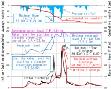
(2) Fig.2 Hydrological time series of Noro-gawa dam. Fig.1 Outline of Noro-gawa river basin.. 2. NORO-GAWA RIVER BASIN: OUTLINE AND DAMAGE. Hiroshima Prefecture. This operation was meant to make the discharge from a dam gradually match the discharge entering the dam. However, the flood control function of the dam is lost under this operation because the river water is not properly stored in the reservoir. Hiroshima Prefecture has a system indicating the dangerous degree of sediment-related disasters1). In this system, Hiroshima Prefecture is divided into 344 gird points, and the dangerous degrees are indicated on the gird points. In this heavy rain disaster, the number of girds exceeding the critical level is 232. The number of the occurrence of the sediment-related disasters was 1,242 in a wide range of Hiroshima Prefecture. The inflow of huge sedimentation and the driftwoods induced the river disasters. Sediment-related disasters frequently occur because of the geological features in Hiroshima Prefecture. This heavy rain disaster is considered as the complex heavy rain disaster of the sediment related disasters and the flooding disasters. Therefore, collaboration between the river bureau and the erosion control bureau becomes critical. Meetings were held to discuss countermeasures for flooding and sedimentation caused by heavy rain and several discussions were conducted. In the Noro-gawa River basin, so many slope failures occurred at Noro-gawa dam located at the upstream side and in the upstream region of Nakahata-gawa River, which is one of the branch rivers. This is a typical example of complex heavy rain disasters. Especially, the huge sedimentation and drift woods influenced the flood operation of Noro-gawa dam. Therefore, we examined the influence of the sediment and the drift woods on Noro-gawa dam and river flooding in the Noro-gawa River basin.. (1) Outline of Noro-gawa River basin As shown in Fig.1, Noro-gawa River originates from the Noro-mountain and passes through Kure City. Noro-gawa River has two branch rivers, Nakahata-gawa River and Nakagiri-gawa River, and finally reaches the Seto Inland Sea. It is 10.5km long with catchment area of 43.2km2. The geologic features around Noro-gawa River consist of dacite and rhyollite2). The Noro-gawa dam is located in the upstream area in Noro-gawa river and the catchment area of this dam is 13.0km2. This area accounts for almost 30% of the area of Noro-gawa River basin. The flood control capacity is 1.05 × 10⁶ m3, and flood control works by the natural control method. The gate opens at 0.42m. (2) Damage in Noro-gawa River basin Figure 2 shows the average rainfall in the upstream area of Noro-gawa dam from 5 July to 9 July in 2018. The maximum 1-hour rainfall was 57.7mm, the maximum 24-hour rainfall was 384.7mm, and the maximum 72-hour rainfall was 621.9mm. These rainfalls were the largest in Hiroshima Prefecture. The return period of the 1-hour rainfall is 50 years and the return period of the 24-hour rainfall is more than 200 years. As shown in Fig.2, the hydrograph of discharge entering Noro-gawa dam has two peaks from nighttime of 6th July to dawn of 7th July. The water level at 22:00 on 6th July was over the water level for starting a disaster prevention operation during abnormal flood. Moreover, it was anticipated that the water level became higher than the surcharge water level. Therefore, a disaster prevention operation. 176.
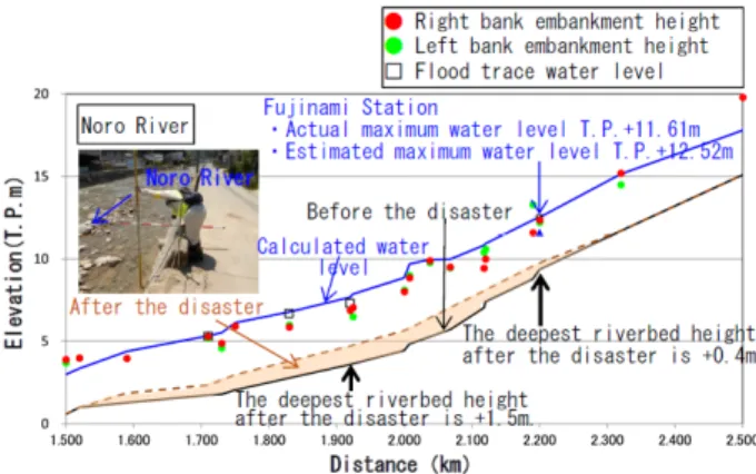
(3) Fig.3 Status of river water level and tide height. Table 1 Damage in Noro-gawa river basin. Disaster Embankment River Bridge loss areas collapse Noro-gawa 20 4 0 Nkahata-gawa 13 6 3 Nakagiri-gawa 8 0 0 Total 41 10 3 ※As of the end of October 2018. Fig.4 Positions of embankment failures and inundation area.. summarized as follows: 1) Noro-gawa dam, Noro-gawa River, Nakahata-gawa River: Decomposition of sediment and driftwood 2) Bridges at the downstream side of the breaking point of the embankment of Nakahata-gawa River: River blockage due to driftwoods 3) The Nakagiri-gawa River where there was little sediment and driftwood: No damage As mentioned above, it may be recognized that the risk of river flooding can increase due to sediments and driftwoods entering the river. We would like to note that the geology of the upper region in the Nakagiri-gawa River is granite and different from the geology of the Noro-gawa River and the Nakahata-gawa River.. during abnormal flood was conducted. This case was the second time in Hiroshima Prefecture. The first peak is larger than the second peak for the rainfall. However, the second peak is larger than the first peak for the inflow discharge. It may be presumed that the effect of the inflow sediments relates to it. This will be discussed in section 3. As shown in Fig.3, the water level observed at Fujinami station located at the downstream side, 2.2km from the river mouth, reached T.P. 11.61m and exceeded the water level of T.P.10.85m at an alarming water level for flooding. It is the highest water level ever recorded. For reference, the tidal height at Miterai Port, which is the nearest port to the Noro-gawa River mouth, is also shown in Fig.3. Fujinami station is not located in the tidal reach and there is no backwater due to the tide. The state of damage in Noro-gawa River basin is shown in Table 1. The revetment failures or similar failures occurred in Noro-gawa River, Nakahata-gawa River, and Nakagiri River. Besides, many bridges were damaged or collapsed. As shown in Fig.4, the inundation in Noro-gawa River basin is induced by the flood and the overflow from Noro-gawa River and the embankment failure in Nakahata-gawa River. We conducted field surveys to identify the mechanisms of damage in the Noro-gawa River basin. A sample survey confirmed an overflow on the embankment at the left bank at Fujinami station. Although the observed highest water level was T.P.11.61m, the actual water level was estimated to reach T.P.12.5m. The main mechanisms of damage of Noro-gawa River basin obtained from the field surveys are. 3. ESTIMATED INFLOW TO NOROGAWA DAM (1) Estimation of inflow discharge and outflow discharge It is important to estimate the inflow discharge and the outflow discharge in order to discuss new dam operations and new action plans for flooding. As shown in Fig.5, a back calculation method is adopted to evaluate the inflow discharge into Noro-gawa dam. This method is based on the balance of the actual outflow discharge and the actual storage volume. In this disaster, the access roads to the dam management office were cut off due to landslides. In addition, telephone lines and LAN were also cut off. The office staff needed to conduct the disaster prevention operation during abnormal flood conditions where there was no information related to the disaster and no one to support them. In such a severe situation, the outflow discharge did not follow the regulation correctly. Besides, a large amount of. 177.
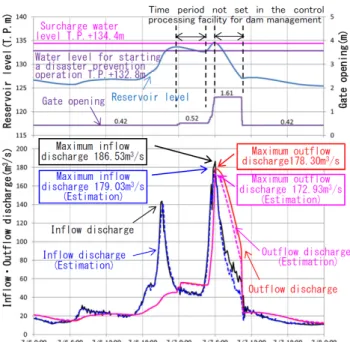
(4) Fig.5 Computation concept of inflow.. Fig.6 Computation concept of inflow with sedimentation. Table 2 Gate operation rule in computation. Event. Gate operation Operation based on the gate A. Starting a disaster prevention operation opening correspondence table B.[A.Outflow discharge]= Inflow discharge Constant reservoir level C.[B.Inflow discharge]= Constant gate opening(0.42m) Maximum planned inflow discharge. Fig.7 Estimation of inflow discharge and outflow discharge.. considering the actual open height of the gate. In Fig.7, the red solid line indicates the actual outflow discharge evaluated with the conventional method, and the pink dotted line indicates the estimated outflow discharge using the corrected discharge coefficient. There is a large discrepancy between them while the open height of the gate is 1.61m, and the evaluated outflow discharge is smaller than the actual outflow discharge. This is why the estimated discharge coefficient is smaller than that of the conventional method, for d is larger in this period. As mentioned previously, the inflow discharge of Noro-gawa dam can be evaluated with the balance of the outflow discharge and the reservoir storage volume. The estimated inflow discharge obtained from the corrected outflow discharge is shown in Fig.7. The black line indicates the actual inflow discharge evaluated with the conventional method, and the blue line indicates the estimated inflow discharge. The estimated maximum inflow discharge to Noro-gawa dam and outflow discharge from Noro-gawa dam were 179 m3/s and 173 m3/s, respectively.. sediment and driftwood flowed into the reservoir. The evaluated inflow and outflow discharges in Noro-gawa dam were influenced by those facts. Therefore, it is necessary to evaluate the inflow discharge due only to rainfall by taking the following items into account as shown in Fig.6: 1) Correction of outflow discharge. 2) Correction of inflow discharge using the corrected outflow discharge. 3) Estimation of inflow discharge due only to rainfall. Elimination of the contribution of sedimentation. The outflow discharge from Noro-gawa dam is calculated according to the regulation shown in Table 2 for the dam management control facility. For the actual operation, the open height of the gate is fixed to 1.61m when the outflow discharge is equal to inflow discharge for the water level of the reservoir to decrease. The discharge water in this stage is an orifice flow, which has no free surface. Torricelli's theorem is used for evaluating the outflow discharge. The discharge coefficient is evaluated with Iwasaki's chart 3). The parameter H/d in this chart is the ratio of the water depth from the water surface to the gate H and the open height of the gate d. Usually, d is constant at 0.42m, so that the discharge coefficient is evaluated only from H. This is the conventional method. On the other hand, in this flooding, the open height of the gate changed from 0.42m to 1.61m as shown in Fig.7 (upper figure). The discharge coefficient must be evaluated with the parameter H/d, which includes the change in d. The actual outflow discharge was corrected. (2) Estimation of inflow of Noro-gawa dam due only to rainfall The corrected inflow discharge consists of the rainfall and the sedimentation because the relationship between the water level of the reservoir H and the reservoir storage volume V varied during the flooding. There was a need to confirm the H-V relationship because of the huge sedimentation disasters in the upstream region of Noro-gawa River and the situation of the dam reservoir after the flooding. So, the inflow discharge due only to rainfall was. 178.
(5) Table 3 H-V relationship before and after disaster. Reservoir level (T.P.m) T.P.+122.4m T.P.+124.4m T.P.+132.8m T.P.+134.4m. Water storage (103 m3) Before After the disaster the disaster 500 447 650 578 1,485 1,365 1,700 1,574. (a) Reservoir plan view. (observation line: 50m interval). (b) Cross-sectional view.. Fig.9 H-V relationship obtained from the estimation. Table 4 Model constants of the storage function method. Plan Identification Model constants value result Watershed constant K 41.7 40.7(0.97 times) Watershed constant P 0.31 0.31 Saturated rainfall Rsa 50mm 350mm Primary runoff rate f1 0.5 0.7 Secondary runoff rate fsa 1.0 1.3. ※Results based on the H-V relationship before and after the disaster. (c) Longitudinal view.. inflow discharge due only to rainfall, a runoff analysis was conducted according to the following procedure: 1) Identification of the model parameters by using the hydrograph which has the first peak. 2) The results of the runoff analysis are assumed to be the inflow discharge due only to rainfall and confirm the transient state of the H-V relationship (see Fig.9). Note that the hydrograph which has the second peak changes after 5:00am on 7th July. The H-V relationship before the disaster will shift to that after the disaster after the sedimentation disaster in the upstream region of Noro-gawa dam occurs. It can be estimated that the H-V relationship after the disaster was shifted around 5:00am 7th July based on the following facts: the staff of the dam management office confirmed the sedimentation disaster occurred at just the upstream side from the dam site; the observed data of Ichihara water level station located near the upstream edge of the dam reservoir was missing at 5:20am 7th July. Table 4 shows the model constants of the storage function method obtained by the above procedure.. Fig.8 Reservoir configuration before and after the disaster.. attempted. In order to determine the bottom topology of the Noro-gawa dam reservoir, a topographic survey was conducted using a UAV Laser system for the land and a multibeam system for the bottom of the reservoir. As shown in Fig.8, a cross-sectional diagram after the disaster was created along the same survey lines as those in the survey conducted in 2017. The H-V relationship can be created by the following procedure: First, the difference between the cross sections before and after the disaster along each survey line was calculated. Second, the storage volumes at several important water levels were calculated using the cross-sectional average method. The storage volumes of Noro-gawa dam are shown in Table 3. The volume of the sedimentation inflowed under the surcharge level was estimated to be 1.26 × 10⁵ m3. This volume accounts for 7.4% of the total volume of Noro-gawa dam 1.70 × 10⁶ m3. The runoff model for the Noro-gawa River basin was the storage function method. To estimate the. 179.
(6) Fig.11 River channel considering the deposition of the sedimentation.. Fig.10 Estimation of inflow discharge and outflow discharge.. The plan values in the table are the constants used conventionally, and the identification results are the constants obtained in this procedure. Comparing both parameters, the watershed constant K of the identification results is slightly smaller than that of the plan, and the saturated rainfall Rsa of the identification results is 7 times that of the plan since the rainfall with weak intensity continues for a long time. The primary runoff rate f1 and the secondary runoff rate fsa of identification results are slightly larger. Figure 10 shows the estimated inflow discharge due only to rainfall. The blue dotted line indicates the estimated inflow discharge mentioned in 3.(1). The green solid line indicates the calculated inflow obtained with the model coefficients with identical results. The simulated inflow discharge around the second peak of the actual inflow discharge is flat and smaller than that of the actual inflow discharge. This difference is considered to be the effect of sediment inflow, and it is presumed that the peak discharge became flat due to continuous rainfall with the same rainfall intensity. The calculated inflow is underestimated on the second decay period. Since the H-V relationship had already been changed to the post-disaster H-V relationship at that time, the supply of the sedimentation was ended. As shown in Figs.9 and 10, the inflow discharge needs to be corrected for the second diminishing part. This diminishing curve was estimated based on the post-disaster H-V relationship.. Fig.12 River channel considering the obstruction by the driftwood.. 4. IMPACT OF SEDIMENTS FLOWING INTO RIVERS. necessary to simulate the flood that occurred in Noro-gawa River basin in order to analyze the inundation factors. The flood simulations were conducted considering the influence of the sedimentation into the river and the flooding discharge was also estimated. The inflow discharge was needed as a boundary condition. However, there was no observation station for the river discharge. There was only the Fujinami station to observe the water level. Moreover, there was no H-Q formula in Noro-gawa River basin. The estimation of flooding discharge was carried out according to the following method4): 1) The flood simulations were conducted using the boundary discharge evaluated by the runoff model, and then verification of the inundation area and the inundation depth was attempted. 2) The validity of the reproduced discharge was confirmed by comparing the computed water levels with the observed marks of the water level.. (1) Computational condition In Noro-gawa River basin, flooding occurred in Noro-gawa River on the downstream side of the Noro- gawa dam, and overflow and three embankment failures occurred in Nakahata-gawa River. It was. (2) Floods simulation model The flood simulation model of Noro-gawa River basin was a plane two-dimensional unsteady flow model. The computational grid interval for spacing was 10m. As shown in Fig.11 and Fig.12,. 180.
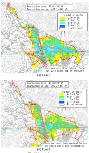
(7) Table 5 Flood simulation conditions. Model cases Objective Case1: When there is no Influence of the sediment inflow into the sedimentation inflow Noro-gawa dam into Noro-gawa dam Case2: When there is no Influence of the river blockage of the river due blockage due to the to sedimentation of the deposition of the river or driftwood under sediment or the drift the bridge woods. the runoff model was performed as described in the previous section. In order to estimate the damaged flow rate in the analysis area, the flow rate of each river was given by trial and error. The damaged flow rate was set so that the inundation range and inundation depth shown in Fig.13 and the water level in the river channel shown in Fig.11 and Fig.12 coincide with the trace water level. The obtained results are shown in Fig.14. The values in the parentheses are the planned high water discharge with 20 years return period. As shown in Fig.14, the discharge into Noro-gawa dam is 150m3/s, which is 1.07 times the planned high water discharge. The difference is small. The flooding discharge at just the downstream side of Noro-gawa dam is 180m3/s. This discharge is much larger than the planned high water discharge. The reason is that the disaster prevention operation during abnormal flood and the flood control did not work for the second peak of the inflow discharge. The flooding discharge at Fujinami station is estimated to be 230 m3/s. The flooding discharge after the conjunction point with Nakagiri-gawa River and Nakahata-gawa River is 430 m3/s.. Fig.13 Estimation of inflow discharge and outflow discharge.. Fig.14 River discharge distribution.. Noro-gawa River was modeled considering the deposition of the sedimentation, and Nakahata-gawa river was modeled by introducing the obstruction by the driftwood at the bridge point to the river channel. To investigate the influence of the sedimentation flow into the river, two river channel models were prepared. One was the river channel without sedimentation and the other was the river channel with sediment deposition. The initial time was set at 5:00am on 7th July. As shown in Fig. 13, There are two drainage pump facilities in the river basin. The capacity of the Tsukimi Park pump station was set at 5.83m3/s, and the capacity of the Urajiri pump station was set at 5m3/s. There were three breaching points of the levee in Nakahata-gawa River. The breaching times were determined based on the results of an interview survey with local residents.. (4) Estimation of inundation volume considering sedimentation Some factors induced the inundation, such as the river blockages due to the sedimentation and drift woods in the Noro-gawa River basin. Therefore, the inundation simulations were conducted in order to investigate the inundation factors in Noro-gawa River basin. Table 5 shows the model cases and their objectives. The influence of the sedimentation inflow into Noro-gawa dam on the inundation in the downstream region is investigated in Case1. The influence of the river blockage due to the deposition of the sediment or the drift woods trapped by bridges on the inundation in the downstream region is investigated in Case2. The inundation simulation was conducted with no sedimentation inflow into Noro-gawa dam in Case1 and with no river blockage in Case2. The simulated inundation areas for Case1 and Case2 are shown in. (3) Estimation of flooding discharge Flooding calculation and flow calculation using. 181.
(8) Table 6 Comparison of the impact of inundation factors. Impact amount Model cases Inundation Inundation area volume 59.4×10⁴ m2 464.4×10³ m 3 Flood record Case1: Influence of the 437.1×10³ m 3 58.0×10⁴ m2 (-1.4×10⁴ m2) (-27.3×10⁴ m2) sedimentation <2.3%> <5.9%> inflowed Case2: Influence of the river blockage due 306.3×10³ m 3 49.3×10⁴ m2 (-10.1×10⁴ m2) (-158.1×10⁴ m2) to the deposition of <17.0%> <34.0%> the sediment or the drift woods. ※( ) : Difference from actual results , < > : Impact rate. because of the river blockages due to the accumulation of the sedimentation and the drift woods trapped by the bridges. The disaster prevention operation during abnormal flood was implemented since it was anticipated that the flood control storage would become empty. This heavy rain disaster was made more complex by sedimentation and river flooding, which are peculiar to Hiroshima Prefecture. This paper reported the influence of sedimentation and driftwoods on Noro-gawa dam on the flooding in the downstream region of Noro-gawa River. The main conclusions are described below. 1) The main factor in the flooding of Noro-gawa dam, Noro-gawa River, and Nakahata-gawa River was the accumulation of the sediment and the drift woods. In particular, the predominant factor in the levee failures in Nakahata-gawa River was the blockage at the downstream side from the breaching points due to the driftwoods trapped by bridges. There was no damage in Nakagiri-gawa River because there was little sedimentation and driftwoods. 2) The back calculation method for evaluating the inflow discharge into Noro-gawa dam needs the actual outflow discharge. The outflow discharge is evaluated with the constant discharge coefficient for the open height of the gate fixed to 0.42m. The inflow and outflow discharges of Noro-gawa dam was evaluated with the discharge coefficients considering the open height of the gate. As a result, it was estimated that the maximum inflow discharge was 179m3/s and the maximum outflow was 173m3/s. 3) The water level of the reservoir and the storage volume were different because of the huge sedimentation and river water flowed into the dam reservoir. The inflow discharge can be estimated by using the storage volume function using the modified model parameters and the corrected H-V relationship considering the influence of the inflow sedimentation for the flood decay period. 4) The flooding discharges in the flooding area in. (a) Case1. (b) Case2 Fig.15 Inundation area.. Fig. 15. A comparison of both figures showed that the inundation area for Case2 became smaller than for Case1 in the area enclosed with the black circle. The results are summarized in Table 6. The inundation area is reduced by 1.4 × 10⁴ m2 in comparison with the actual inundation area. The reduction rate is 2.3%. The inundation volume is reduced by 27.3 × 10³ m3 and its reduction rate is 5.9%. For Case2, the inundation area is reduced by 10.1 × 10⁴ m2 and the inundation volume is reduced by 158.1 × 10³ m3. The reduction rates are 17.0% and 34.0%, respectively. It can be seen from these results that the inundation in the downstream side of Noro-gawa dam was affected by the river blockage more than the sedimentation inflow into Noro-gawa dam.. 5. CONCLUSIONS The Noro-gawa River basin had heavy rain in July 2018. The overflow from Noro-gawa river and Nakahata-gawa River and the levee failures occurred. 182.
(9) the downstream region of Noro-gawa River were estimated by using the numerical inundation simulation. As a result, the flooding discharge at just the downstream side of Noro-gawa dam was 180 m3/s, that at Fujiwara station was 230 m3/s, and that after the conjunction point with two branch rivers was 430 m3/s. 5) The inundation in the downstream side of Noro-gawa dam was affected by the river blockage more than the sedimentation inflow into Noro-gawa dam. The flood control capacity and the distribution of the river discharge must be determined for Noro-gawa River and Nakahata-gawa River in order to guarantee the flood control safety level of the Noro-gawa dam in the future. Moreover, an effective dam control utilizing technology to predict the inflow and management of the inflow sediment are also important issues.. ACKNOWLEDGMENT: We would like to express our appreciation to the members of the committee for their valuable advice contained in the “Future flood and sediment disaster countermeasures study meeting based on July 2018 heavy rain disaster”. REFERENCES. 1) 2) 3) 4). Hiroshima sediment risk information: http://www.d-keikai. pref.hiroshima.lg.jp/public/MapForm.aspx Geology Navi: https://gbank.gsj.jp/geonavi/geonavi.php# 16,34.29074,132.70406 Japan Society of Civil Engineers: Hydraulics Official Collection, revised in 1969, edited by Japan Society of Civil Engineers, pp. 278, 1971. Ministry of Land, Infrastructure, Transport and Tourism: Basic policy for disaster recovery to protect beautiful mountains and rivers, June 2018, pp. 160, 2018. (Received August 28, 2020) (Accepted November 20, 2020). 183.
(10)
図


+4

関連したドキュメント
Standard domino tableaux have already been considered by many authors [33], [6], [34], [8], [1], but, to the best of our knowledge, the expression of the
The edges terminating in a correspond to the generators, i.e., the south-west cor- ners of the respective Ferrers diagram, whereas the edges originating in a correspond to the
H ernández , Positive and free boundary solutions to singular nonlinear elliptic problems with absorption; An overview and open problems, in: Proceedings of the Variational
An easy-to-use procedure is presented for improving the ε-constraint method for computing the efficient frontier of the portfolio selection problem endowed with additional cardinality
Keywords: Convex order ; Fréchet distribution ; Median ; Mittag-Leffler distribution ; Mittag- Leffler function ; Stable distribution ; Stochastic order.. AMS MSC 2010: Primary 60E05
In Section 3, we show that the clique- width is unbounded in any superfactorial class of graphs, and in Section 4, we prove that the clique-width is bounded in any hereditary
Inside this class, we identify a new subclass of Liouvillian integrable systems, under suitable conditions such Liouvillian integrable systems can have at most one limit cycle, and
Then it follows immediately from a suitable version of “Hensel’s Lemma” [cf., e.g., the argument of [4], Lemma 2.1] that S may be obtained, as the notation suggests, as the m A
