Emulator of Variable-Speed Wind Power
Generation System using Boost Chopper
Circuit of Permanent Magnet Synchronous
Generator
By
Sirichai Tammaruckwattana
A thesis submitted in partial fulfilment for the requirements of
the degree of Ph.D. (by Research) at the
Fukuoka Institute of Technology
I
ABSTRACT
This thesis verifies the performance of a Variable-Speed Wind Power Generation System (VSWPGS) using Permanent Magnet Synchronous Generator (PMSG) and Boost Chopper Circuit (BCC) experimentally. The assessments are conducted with a test bench using a Wind Turbine Emulator (WTE). The WTE reproduces the shaft torque of a wind turbine (WT) for an arbitrary wind velocity by the servo motor drives. The shaft-torque reference of servo motor drive is estimated in real time based on the blade element momentum theory (BEMT) by using windmill wing profiles, wind velocity data, and windmill rotational speed. Also the difference of inertia between the WT and the servo motor is compensated simultaneously. The WTE is newly-proposed for the experimental assessment. The tested VSWPGS using BCC has three speed control modes to the wind velocity. By combining the three control modes, the VSWPGS using BCC can extend the variable speed range more than conventional control methods. The experimental assessments shows that the VSWPGS using the BCC can reduce the costs while improving the reliability of the whole system, and has the same performance as the VSWPGS using a PWM converter of benchmark.
主論文の要旨
本論文は,永久磁石同期発電機(PMSG)を前提とする昇圧チョッパ 回路(BCC)を用いる可変速風力発電システム(VSWPGS)の実機検証を行 う。実機検証は,風車エミュレータ(WTE)を使用するテストベンチによっ て行う。WTEは,サーボモータドライブにより任意の風速に対する風車ター ビン(WT)の軸トルクを再現する。サーボモータドライブに与える軸トルク 指令は,翼素運動量理論に基づいて,風車翼プロファイル,風速データ,そ して風車回転速度からリアルタイムに演算され,同時にサーボモータとWTの イナーシャの違いも補償される。WTEは実機検証のために新規に提案するも のである。実機検証するBCCを用いるVSWPGSは,風速に応じた3つの制御モ ードを有する。3つの制御モードを組み合わせることにより,BCCを用いる VSWPGSは,従来の制御方式よりも可変速範囲を広げることができる。実機 検証により,BCCを用いたVSWPGSが,システム全体の信頼性を向上させつ つコスト削減を達成し,ベンチマークであるPWMコンバータを用いる VSWPGSと同等の性能を有することを示す。II
CONTENTS
Acknowledgements...VIII
List of Abbreviations... IX
List of Figures... XI
List of Tables... XVII
Chapter 1: Introduction... 1
1.1 Background introduction ... 1
1.2 Aims and objectives………3
1.3 Structure of thesis... 5
Chapter 2: Operation principle of the variable-speed wind power generation system………... 7
2.1 Introduction………... 7
2.2 Wind turbine control for grid connection……….……….8
2.2.1 Direct-coupled generator……….………….……8
2.2.2 Doubly-fed induction generator (DFIG)……….……..9
III
2.2.4 AC/DC Rectifier and DC/ DC converter………....………11
2.2.5 Comparison between Direct Torque Control and Field Oriented Control……….………14
2.3 System configuration………... 16
2.4 Boost chopper scheme…….………... 16
2.5 back to back PWM converter scheme...………... 19
2.6 Summary……….………..…………20
Chapter 3: Assessment with simulation of the variable speed wind power generation system………... 21
3.1 Modeling method………...……….21
3.2 Windmill model………..………..22
3.3 Pitch angle control system………..………..31
3.4 Mechanical model for wind turbine………..32
3.5 Mechanical model for wind turbine emulator………..34
3.6 PMSG and converter main circuit………36
3.6.1 Modeling of boost chopper method………..…….……37
3.6.2 Modeling of PWM converter method………..….……….51
3.7 Mechanical system………52
3.8 DC link division………53
3.8.1 Modeling of boost chopper method……….……...53
3.8.2 Modeling of PWM converter method……….57
IV
3.9.1 Modeling of boost chopper method……….………...59
3.9.2 Modeling of PWM converter method……….………62
3.10 Power system and inverter main circuit………..65
3.11 Inverter control system………...……….66
3.11.1 Modeling of boost chopper method……….……….67
3.11.2 Modeling of PWM converter method………..……….70
3.12 MATLAB Simulink model of the Boost chopper method………..71
3.12.1 PI gain of the boost chopper scheme……….72
3.13 MATLAB Simulink model of the PWM converter method……….……..77
3.13.1 PI gain of the PWM converter scheme……….78
3.14 Simulation results of the Boost chopper method……….…...83
3.15 Simulation results of the PWM converter method………..…….…...89
3.16 Summary………..……...94
Chapter 4: Wind Turbine Emulator……….………..95
4.1 Wind turbine emulator………..95
4.2 Blade element momentum theory………..97
4.3 Airfoil profiles……….…..99
4.3.1 Fluid analysis using finite element method software ANSYS....99
4.3.2 Analysis results due to the ANSYS……….…..…100
4.4 Mechanical model………..…………...109
4.5 System configuration of WTE……….………..…..110
V
4.7 Experimental system of wind turbine emulator (PWM converter scheme)113 4.8 Change of the wind velocity of wind turbine emulator. (PWM converter
scheme)……….………..….115
4.9 Experimental results of wind turbine emulator (PWM converter scheme).116 4.10 Simulation results of wind turbine model (PWM converter Scheme).…124 4.11 Natural wind velocity of real wind turbine (PWM converter scheme)...132
4.12 Experimental results of real wind turbine (PWM converter scheme).…133 4.13 Experimental results of wind turbine emulator (PWM converter scheme)………..………..137
4.14 Summary……….……….141
Chapter 5: Experimental assessment of variable speed wind power generation system………..……….…….142
5.1 Performance evaluation scheme………..142
5.2 Experimental system of wind turbine emulator (Boost chopper scheme)...142
5.3Experimental system of wind turbine emulator (PWM converter scheme).144 5.4 Phase locked loop (PLL) control system……….………..…..146
5.5 Laboratory prototype………...147
5.6 Structure of wind turbine emulator……….148
5.7 Structure of real wind turbine……….…149
5.8 Experimental results of wind turbine emulator (Boost chopper scheme)...150
5.9 Experimental results of wind turbine emulator (PWM converter scheme).158 5.10 Experimental system of real wind turbine (Boost chopper scheme).…...166
5.11 Experimental results of real wind turbine (Boost chopper scheme).…....168
5.12 Experimental results of wind turbine emulator (Boost chopper scheme).173 5.13 The each element of the system………..……….……….177
VI
5.13.1 Boost chopper scheme……….………..177
5.13.2 PWM converter scheme……….………177
5.14 Summary……….……….……….179
Chapter 6: Conclusion and Discussion…... 180
6.1 Conclusion and Discussion…...181
References...182
Appendix-A FPGA control for PWM converter………...………192
Appendix-B FPGA control for boost chopper scheme…………...………199
Appendix-C Rotary Encoder Parameter….……….……….207
Appendix-D MWINV-4R222……….………..208
VII
Acknowledgements
I would like to express my sincere thanks to my thesis adviser, Prof. Kazuhiro Ohyama for his invaluable help and constant encouragement throughout the course of this research. I am most grateful for his teaching and advice, not only the research methodologies but also many other methodologies in life.
I would also like to extend my thanks to the technicians of the laboratory of the manufacturing center department for their help in offering me the resources in research. And my thanks go to all research colleagues, in Ohyama laboratory for harmonious atmosphere.
I would also like to extend my thanks to the Royal Thai Government Scholarship for Science and Technology, Ministry of Science and Technology for their support throughout my study.
I would like to express my gratitude to the authority and all members of staff at the Fukuoka Institute of Technology for the support and opportunity they provided for me to be a student of the institution. I am proud of you all.
Finally, I wish to thank my parents for their support and encouragement throughout my study.
VIII
List of Abbreviations
AC Alternating Current
BEMT Blade Element Momentum Theory BCC Boost Chopper Circuit
DSP Digital Signal Processing DC Direct Current
FPGA Field Programmable Gate Array FEM Finite Element Method
IGBT Insulated Gate Bipolar Transistor
NACA National Advisory Committee for Aeronautics PMSG Permanent Magnet Synchronous Generator PWM Pulse Width Modulation
IX
List of Symbols
V0 rotor inflow wind speed [m/s]
u wind speed before passing the rotor [m/s]
u1 wind speed after passing the rotor [m/s] R rotor radius [m]
rotor angler speed [rad/s]
blade pitch angle [rad]
W blade inflow wind speed [m/s]
inflow angle [rad]
meeting angle [rad]
L lift
D drag
a , a’ interference factor
c wind of code [m]
vau, vav, vaw armature voltages
iau, iav, iaw armature currents
eau, eav, eaw speed electromotive forces for permanent magnet field
Ra armature winding resistance
X
Ma’ mutual inductance of armature winding
ωge rotor angular speed (electrical angle)
θge rotor position (electrical angle)
p time derivative operator
R line resistance of power system
Ls line inductance of power system
ωs angular frequency of power system
isd , isq dq-axis current for inverter side [A]
ωs grid system angular frequency [rad/s]
Ls line inductance [H]
isd , isq dq-axis current for inverter side [A]
Vsd , Vsq dq-axis voltage for inverter side [V]
Rs line resistance [W]
esd dq transform of inverter side
Q The generated torque of the wind turbine side
Tg The generated torque of the generator side
T1 The shaft torque of the wind turbine side T2 The shaft torque of the generator side
ωt The rotor rotational angler speed of wind turbine side
ωg The rotor rotational angler speed of generator side
Bt The viscous friction coefficient of the wind turbine side
Bg The viscous friction coefficient of the generator side
Jt The moment of inertia of the wind turbine side
Jg The moment of inertia of the generator side
Tim The generated torque of the induction motor side
XI
ωim The rotor rotational angler speed of induction motor side
Bim The viscous friction coefficient of the induction motor side
Jim The moment of inertia of the induction motor side
idc1 Current flowing through the diode bridge rectifier circuit [A]
DU1 Diode maximum voltage side of the diode bridge rectifier circuit
DV2 Diode minimum voltage side of the diode bridge rectifier circuit
Ldc Inductance of the step-up chopper circuit [H]
rL Resistance of inductance itself of the step-up chopper circuit []
Tr Switch of the boost chopper circuit
rT Switching resistance []
D Diode of the boost chopper circuit
rD Resistance of the diode itself of the boost chopper circuit []
Cdc DC link capacitor [F]
Rdc DC link resistance []
Vdc DC link voltage [V]
Q generated torques for windmill
Tg generated torques for PMSG sides
T1 shaft torques for windmill T2 shaft torques for PMSG sides
ωg Rotor angular speed (mechanical angle)
Bt Viscous friction coefficient for windmill
Bm Viscous friction coefficient for PMSG sides
Jt moments of inertia for windmill
Jm moments of inertia for PMSG sides
n1/n2 gear ratio.
Tg generator torque [Nm]
P stator pole Фfa stator flux [Wb]
iaq q-axis current [A]
ωg generator speed [rad/s]
XII
Jm PMSG moment of inertia [kgm2]
Jt windmill moment of inertia [kgm2]
Bm coefficient of viscosity for PMSG [Nm/(rad/s)]
Bt coefficient of viscosity for wind turbine [Nm/(rad/s)].
iad, iaq dq-axis current [A]
ωge angular velocity of the field (electrical angle) [rad/s]
La stator inductance [H]
Vad, Vaq dq-axis voltage [V]
Ra stator resistance [W]
XIII
List of Figures
Figure 2.1 Fixed-speed wind turbine……….………..9
Figure 2.2 Doubly-fed induction generator (DFIG) wind turbine…….…………10
Figure 2.3 Fully rated converter grid connection………..…………10
Figure 2.4 Wind turbine PMSG with back to back PWM converter……….……12
Figure 2.5 Wind turbine generator with diode bridge rectifier……….….13
Figure 2.6 Wind turbine generator with diode bridge rectifier and boost chopper circuit………14
Figure 2.7 VSWPGS using PMSG of boost chopper method ………..…………18
Figure 2.8 VSWPGS using PMSG of PWM converter method …………..….…20
Figure 3.1 Annular floe tube……....……….……….…22
Figure 3.2 Velocity triangle………..……….…23
Figure 3.3 Wind turbine blade shape model………..…27
Figure 3.4 Wind turbine speed reference and electric power reference to keep maximum conversion factor……….……..….….…28
Figure 3.5 Logic for control of wind turbine……….…....………30
Figure 3.6 Timing to change control method………..……….…..…...…31
XIV
Figure 3.8 Windmill turbine model……….……..……33 Figure 3.9 Simulink and system block of wind turbine ……….………..….……34 Figure 3.10 Windmill turbine emulator model…….………..….……35 Figure 3.11 Simulink and system block of wind turbine emulator…………..……36 Figure 3.12 Simulink and model Equivalent circuit of PMSG…….……...………39 Figure 3.13 U-phase, V-phase main circuit of (conduction mode ①)……..….…41
Figure 3.14 U-phase, W-phase main circuit of (conduction mode ②)……….…..41
Figure 3.15 V-phase, W-phase main circuit of (conduction mode ③)……..…...42 Figure 3.16 V-phase, U-phase main circuit of (conduction mode ④)………...…42 Figure 3.17 W-phase, U-phase main circuit of (conduction mode ⑤)……….…..43 Figure 3.18 W-phase, V-phase main circuit of (conduction mode ⑥)…………...43 Figure 3.19 Simulink model to detect conduction mode……….46 Figure 3.20 Simulink and model Simplified converter main circuit of conduction
mode 1………..………49 Figure 3.21 Model of PWM converter main circuit………....……....52 Figure 3.22 Simulink and model DC link model of boost converter method……..54 Figure 3.23 Simulink and model Simplified DC link model of boost converter
method……….……….57 Figure 3.24 Simulink and model DC link model of PWM converter method …....59 Figure 3.25 Duty ratio control system……….61 Figure 3.26 PWM converter control system……….………...……64 Figure 3.27 System and main circuit of PWM inverter………...……66
XV
Figure 3.28 Inverter control system of boost converter method………..69
Figure 3.29 Inverter control system of PWM converter method……….…70
Figure 3.30 MATLAB Simulink block of the Boost chopper method………...….71
Figure 3.31 Current control system of inverter………74
Figure 3.32 MATLAB Simulink block of the PWM converter method …….……77
Figure 3.33 Speed control system of the PWM converter method….………….…79
Figure 3.34 Current control system of converter……… ………82
Figure 3.35 Generated power of Boost chopper scheme....………..….……..84
Figure 3.36 Wind turbine Torque……….….…………..84
Figure 3.37 Tip speed ratio……….……….85
Figure 3.38 Rotational speed reference and Rotational speed……….…85
Figure 3.39 Duty cycle……….……...86
Figure 3.40 d-axis and q-axis voltage for converter side………....…….86
Figure 3.41 d-axis and q-axis current for converter side………..….…..87
Figure 3.42 d-axis and q-axis current for inverter side……….……..…….87
Figure 3.43 DC link voltage and its reference……….……88
Figure 3.44 Generated power of PWM converter scheme……….….….……90
Figure 3.45 Wind turbine Torque……….……….……..90
Figure 3.46 Tip speed ratio……….……….91
Figure 3.47 Rotational speed reference and Rotational speed……….………91
Figure 3.48 q-axis current for feed-forward reference………..…….….92
XVI
Figure 3.50 d-axis and q-axis current for converter side………...……..93
Figure 3.51 d-axis and q-axis current for inverter side………93
Figure 3.52 DC link voltage and its reference……….…………94
Figure 4.1 Wind turbine emulator……….………96
Figure 4.2 Wind turbine blade shape model……….….………96
Figure 4.3 Real wind turbine blade shape……….………….………97
Figure 4.4 XY coordinate data of NACA4415……….………..…….100
Figure 4.5 The angle of attack of 0 [deg] of the wind vector illustration…...….101
Figure 4.6 The angle of attack of 0 [deg] of the wind velocity distribution…....101
Figure 4.7 The angle of attack of 0 [deg] of the pressure distribution……...….102
Figure 4.8 The angle of attack of -10[deg]………..……102
Figure 4.9 The angle of attack of -10 [deg] of the wind vector illustration….…103 Figure 4.10 The angle of attack of -10 [deg] of the wind velocity distribution….103 Figure 4.11 The angle of attack of -10 [deg] of the pressure distribution…..…...104
Figure 4.12 The angle of attack of +10[deg]………..………….…..104
Figure 4.13 The angle of attack of +10 [deg] of the wind vector illustration…....105
Figure 4.14 The angle of attack of +10 [deg] of the wind velocity distribution…105 Figure 4.15 The angle of attack of +10 [deg] of the pressure distribution…...….106
Figure 4.16 Calculated wind turbine blade performance output result………..…107
Figure 4.17 Windmill output torque………..…108
Figure 4.18 Windmill output power………..…108
XVII
Figure 4.20 Mechanical model for wind turbine emulator………...…….110
Figure 4.21 WTE base on BEMT……….….111
Figure 4.22 Experimental systems using the real wind turbine (PWM converter scheme)…………..………..………..….112
Figure 4.23 Experimental systems using the wind turbine emulator (PWM converter scheme)…………..……….…………..……….…….114
Figure 4.24 Wind velocity……….……115
Figure 4.25 Generated power……….….………...117
Figure 4.26 Wind turbine Torque……….……….117
Figure 4.27 Thrust……….………118
Figure 4.28 Tip speed ratio……….…….……..118
Figure 4.29 Power reference………..………119
Figure 4.30 Rotational speed Reference……….…..……….119
Figure 4.31 Rotational speed……….…………120
Figure 4.32 d-axis and q-axis current for converter side………..……….120
Figure 4.33 Integrated power……….………121
Figure 4.34 q-axis current reference of feed-forward control …………..………121
Figure 4.35 q-axis current reference of Speed regulator……….…..……122
Figure 4.36 q-axis current Reference of Power regulator……….….…122
Figure 4.37 DC link voltage and its reference……….……..123
Figure 4.38 d-axis and q-axis current for inverter side………...…...123
XVIII
Figure 4.40 Wind turbine Torque……….……….125
Figure 4.41 Thrust……….………126
Figure 4.42 Tip speed ratio………....….….……..126
Figure 4.43 Power reference……….….……127
Figure 4.44 Rotational speed Reference………..….…….127
Figure 4.45 Rotational speed……….………128
Figure 4.46 d-axis and q-axis current for converter side………..……….128
Figure 4.47 Integrated power……….……129
Figure 4.48 q-axis current reference of feed-forward control ………..……129
Figure 4.49 q-axis current reference of Speed regulator…………..……….……130
Figure 4.50 q-axis current Reference of Power regulator……….……130
Figure 4.51 DC link voltage and its reference……….……..131
Figure 4.52 d-axis and q-axis current for inverter side……….……...131
Figure 4.53 Natural wind velocity of the real wind turbine……….……..…132
Figure 4.54 Generated power and system power of the real wind turbine………134
Figure 4.55 Tip speed ratio of the real wind turbine……….…134
Figure 4.56 Rotational speed Reference and Rotational speed of the real wind turbine……….…135
Figure 4.57 d-axis and q-axis voltage reference for converter side of the real wind turbine……….………135
Figure 4.58 DC link voltages and its reference of the real wind turbine……..….136
XIX
Figure 4.60 Generated power and system power of the wind turbine emulator....138
Figure 4.61 Tip speed ratio of the wind turbine emulator………...……..138
Figure 4.62 Rotational speed Reference and Rotational speed of the wind turbine emulator………..…139
Figure 4.63 d-axis and q-axis voltage reference for converter side of the wind turbine emulator………..…...139
Figure 4.64 DC link voltage and its reference of the wind turbine emulator……140
Figure 4.65 d-axis and q-axis current for inverter side of the wind turbine emulator……….….140
Figure 5.1 Experimental systems using the wind turbine emulator (Boost chopper scheme)……….……….……… …………143
Figure 5.2 Experimental systems using the wind turbine emulator (PWM converter scheme)……….………..……145
Figure 5.3 Structure of phase locked loop control system… ………..…146
Figure 5.4 Laboratory Prototype………..…....147
Figure 5.5 Structure of the wind turbine emulator…...………...….…148
Figure 5.6 Structure of the real wind turbine ………..………..….….…149
Figure 5.7 Change of wind velocity………..……….………….……150
Figure 5.8 Rotational speed reference and Rotational speed of boost chopper scheme………...….……152
Figure 5.9 Duty control signal of boost chopper scheme……….…...……152
Figure 5.10 Wind turbine torque of boost chopper scheme……….…….153
Figure 5.11 Tip speed ratio of boost chopper scheme……….….….153
XX
Figure 5.13 Power set of boost chopper scheme………...…154 Figure 5.14 DC link voltage and its reference of boost chopper scheme……..…155 Figure 5.15 System power of boost chopper scheme………155 Figure 5.16 Pitch angle control of boost chopper scheme……….………156 Figure 5.17 d-axis and q-axis current of boost chopper scheme……….…….….156 Figure 5.18 d-axis and q-axis voltage for converter side of boost chopper scheme
………157 Figure 5.19 d-axis and q-axis voltage for inverter side of boost chopper scheme
………..……..…157 Figure 5.20 Rotational speed reference and Rotational speed of the PWM converter scheme………..….….159 Figure 5.21 q-axis current reference of feed-forward control of the PWM converter
scheme………...…….159 Figure 5.22 Wind turbines Torque of the PWM converter scheme………...…160 Figure 5.23 Tip speed ratio of the PWM converter scheme………....…..160 Figure 5.24 Integrated power system of the PWM converter scheme………..….161 Figure 5.25 Power set of the PWM converter scheme……….…….……161 Figure 5.26 DC link voltages and its reference of the PWM converter scheme....162 Figure 5.27 System power of the PWM converter scheme………..….162 Figure 5.28 Pitch angle control of the PWM converter scheme…………..…..…163 Figure 5.29 d-axis and q-axis current for converter side of the PWM converter
scheme………...……….…163 Figure 5.30 d-axis and q-axis voltage of the PWM converter scheme………..…164
XXI
Figure 5.31 q-axis current reference of power regulator control of the PWM
converter scheme………164 Figure 5.32 Experimental systems using the real wind turbine (Boost chopper
scheme)……….……….…….167 Figure 5.33 Natural wind velocity of the real wind turbine ……….……….168 Figure 5.34 Generated power and system power of the real wind turbine …..….170 Figure 5.35 Rotational speed Reference and Rotational speed of the real wind
turbine ………..…..170 Figure 5.36 Torque for wind turbine ……….……….……..171
Figure 5.37 d-axis and q-axis voltage reference for converter side of the real wind
turbine ……….……….…….….171 Figure 5.38 DC link voltages and its reference of the real wind turbine ….…….172 Figure 5.39 d-axis and q-axis current for converter side of the real wind
turbine……….………. ..172 Figure 5.40 Generated power and system power of the wind turbine emulator ...174 Figure 5.41 Rotational speed Reference and Rotational speed of the wind turbine
emulator………..….174 Figure 5.42 Torque for wind turbine ……….……...175 Figure 5.43 d-axis and q-axis voltage reference for converter side of the wind
turbine emulator………..…...175 Figure 5.44 DC link voltages and its reference of the wind turbine emulator …..176 Figure 5.45 d-axis and q-axis current for converter side of the wind turbine
XXIII
List of Table
Table 3.1 Conduction mode of diode bridge rectifier ……….44 Table 3.2 Common parameters of boost chopper scheme and PWM converter
scheme……….…….75 Table 3.3 Control parameters of boost chopper scheme ………...….…….76 Table 3.4 Control parameters of PWM converter scheme...80 Table 4.1 Three-dimensional table data……….………...97 Table 4.2 Airfoil profile result……….98 Table 5.1 Integrated power of each mode………..165
1
Introduction
1.1 Background
The power of the wind has been utilized for at least the past 3000 years [1]. Until the early 20th century wind power was used to provide mechanical power to pump water or to grind grain. At the beginning of modern industrialization, the use of the fluctuating wind energy resource was substituted by fossil fuel fired engines or the electrical grid, which provided a more consistent power source. In the early 1970s, with the first oil price shock, the interest in the power of the wind re-emerged. This time, however, the main focus was on wind power providing electrical energy instead of mechanical energy. This way, it became possible to provide a reliable and consistent power source by using other energy technologies, via the electrical grid, as a back-up. The first wind turbines for electricity generation had already been developed at the beginning of the 20th century. The technology was improved step by step since the early 1970s. By the end of the 1990s, wind energy has re-emerged as one of the most important sustainable energy resources. During the last decade of the 20th century, worldwide wind capacity has doubled approximately every 3 years. The costs of electricity generated from wind power have fallen to about one-sixth since the early 1980, and the trend seems to continue. Some experts predict that the cumulative capacity will be growing worldwide by about 25% per year until 2005. Wind energy technology itself also moved very fast towards new dimensions. At the end of 1989, a 300 kW wind turbine with a 30-m rotor diameter was state-of-the-art. Only 10 years
2
later, 1500 kW turbines with a rotor diameter of around 70 m are available from many manufacturers. The first demonstration projects using 2 MW wind turbines with a rotor diameter of 74 m was installed before the turn of the century. Four and five MW wind turbines are expected to become available in 2001 or 2002.
In the last 12 years, A Survey of Control Issues in PMSG-Based Small Wind-Turbine Systems in 2013 [2]. The penetration of the wind-turbine power generation is dramatically increased worldwide. This growing trend is stimulating the research in the power processing field aiming at optimizing the energy extraction from the wind and the energy injection into the grid [4]. Particular interest has been focused in recent years on distributed generation through small wind-turbines because of: lower impact on the landscape, lower noise level, grid codes and national laws imposing simpler grid connection and higher feed-in tariffs and capability to work in island-mode for isolated communities [5].
As power generating systems which can utilize renewable wind energy effectively, the researches of variable-speed wind generator systems which change windmill rotational frequency in proportion to the wind velocity are widely carried out [6-32]. The energy conversion efficiencies of propeller windmills change for conditions of wind velocity and windmill speed. Therefore the converter connected with a generator must control the windmill speed in proportion to the wind velocity in order to maintain the energy conversion efficiency maximum [33].
At present, the variable-speed wind generator systems using the PWM converter (PWM converter method) are introduced [34-56]. The PWM converter is costly because a lot of switching devices are used and its control system is complicated. However, the PWM converters are used for large-capacity variable-speed wind generator systems which need windmill speed control, because the vector control can be applied to realize the high-speed and high-precise generator torque control.
The converter does not need to supply the excitation energy when the permanent magnet synchronous generator (PMSG) is used as a generator [57-59]. Therefore, the wind generator system for the purpose of battery charger uses the diode bridge rectifier as a converter. It is operated mainly at the rated wind velocity since the induced voltage is enough to charge the battery [75-78]. The wind generator systems
3
using diode bridge rectifier (diode rectification method) can constitute low-cost converters [60-68]. However, the windmill speed control becomes difficult, since the converter cannot control the PMSG torque by itself. And, the induced voltage necessary for system interconnection cannot be obtained at low wind velocity. At present, the diode rectification method which realizes the windmill speed control and system interconnection simultaneously at low wind velocity is not reported.
This thesis will address the generator control of a small wind turbine for grid connection. The wind turbine extracts the energy from the wind through the rotor blade, which drives the generator to produce electricity.
This thesis focuses on 3-phase AC Permanent Magnet Synchronous Generator (PMSG). And the research has been focused on the development of a new turbine design to reduce the cost of wind power and to make wind turbines more economical and efficient. The investigation of wind power system involves high performance wind turbine emulators, especially for the development of optimal control solutions. For the effective utilization of renewable wind energy by power generating systems, a large number of studies are being conducted on variable-speed wind generator systems that change the windmill rotational frequency in proportion to the wind velocity. The energy conversion efficiency of propeller windmills depend on wind velocity and windmill speed. Therefore, the converter connected to the generator must control the windmill speed in proportion to the wind velocity in order to maintain the maximum energy conversion efficiency.
1.2 Aims and objectives
This thesis focuses on an experimental verification of a variable-speed wind power generation system (VSWPGS).
First, is the whole simulation system consists of models of PMSG, AC/DC converter, AC/DC rectifier, DC link, Boost chopper circuit, DC/AC inverter, and grid voltage monitoring unit, which are detailed below. The objectives of the simulation system are to develop the above mentioned mathematical and simulation models, and to verify the models through a case study simulation.
4
Second, is the whole experimental system model in laboratory consists of models of wind turbine emulator, PMSG, AC/DC converter, AC/DC rectifier, DC link, Boost chopper circuit, DC/AC inverter, Transformer and grid line, which are detailed below. The objectives of the experimental system are to develop the above mentioned mathematical and control circuit models, and to verify the models through a case study experimental in laboratory.
Third, is the experimental verification of a variable-speed wind power generation system using real wind turbine consists of models of real blade wind turbine, PMSG, AC/DC converter, AC/DC rectifier, DC link, Boost chopper circuit, DC/AC inverter, Anemometer, Transformer and grid line, which are detailed below. The objectives of the experimental system of a variable-speed wind power generation system using real wind turbine are to develop of a new turbine design to reduce the cost of wind power and to make wind turbines more economical and efficient. are detailed below. the experimental verification of a variable-speed wind power generation system using a permanent magnet synchronous generator and a boost chopper with three speed control modes for wind velocities. The control system is used for the VSWPGS using the diode bridge rectifier and boost chopper circuit as a converter (boost chopper scheme). The speed control mode of low wind velocity controls the windmill speed by controlling the PMSG torque with the boost chopper circuit. The boost chopper circuit can control the generator torque by adjusting the armature current of the PMSG. The speed control mode of middle wind velocity controls the windmill speed by controlling the PMSG torque with the system interconnection inverter. The system interconnection inverter can control the PMSG torque by adjusting the DC link voltage. The speed control mode over the rated wind velocity controls the windmill speed by controlling the windmill torque with the pitch angle control system. The pitch angle control system can control the windmill torque by adjusting the pitch angle. The extension of the variable-speed range is realized by using the hybrid control of three speed control modes, consequently, the system interconnection for all speed control modes. In comparison with the PWM converter scheme, the proposed control system has two advantages. First one is the cost reduction produced by reducing the number of switching devices, and second one is high reliability produced by simplifying the main circuits and control circuits.
5
1.3 Structure of the Thesis
This thesis is organized with following ways:
Chapter 2: Operating principle of the variable-speed wind power generation system The structures and operation principles of the VSWPGS using PMSG used for system interconnection are described. Each control principle of VSWPGS using BCC or PWM converter handled in this thesis is explained. The differential equations describing the systems, which are necessary for modeling in simulation, are explained.
Chapter 3: Assessment with simulation of the variable-speed wind power generation system
The modeling method using MATLAB/Simulink is explained. The modelling is conducted based on the simultaneous differential equations describing each system. Also, this chapter explains the modeling method of the wind turbine (WT). The design method for control parameters of the VSWPGS using BCC or PWM converter are explained, and the parameters necessary for the simulation are shown. The simulation is conducted for the conditions of the low, medium and high wind velocity. The simulation results for each VSWPGS are shown, and the validity of the control principle for each VSWPGS is proved.
Chapter 4: Wind turbine emulator
This chapter explains the operating principle and the structure of Wind turbine emulator (WTE) based on the BEMT. Also the structures of the test benches using the WT or WTE are explained. The simulation results of the VSWPGS using PWM converter are compared with the experiment results obtained with the test bench using WTE under the same conditions of low, medium, and high wind velocities. Furthermore, under the conditions of natural winds, the experiment results obtained with the bench using WTE or WT for the VSWPGS using PWM converter are shown.
6
The obtained experimental results show that the proposed WTE has a sufficient performance for the experimental assessment.
Chapter 5: Experimental assessment of variable speed wind power generation system The experimental assessment for the VSWPGS using PWM converter or BCC are conducted with the test bench using WTE under the conditions of low, medium, and high wind velocities. By comparing the experimental results of both VSWPGSs, it is shown that the VSWPGS using BCC can extend the variable speed ranges compared to conventional control methods. Also the each element of the system, which are used for experimental assessments, is considered. Then it is shown that the VSWPGS using BCC can reduce the costs and improve the reliability of the whole system, and has the same performance with the VSWPGS using PWM converter of a benchmark.
Chapter 6: Conclusion
The comprehensive discussions based on the obtained results are conducted, and the obtained research outcomes are clarified.
7
Chapter 2
Operation principle of the
variable-speed wind power
generation system
2.1 Introduction
This chapter shows the literature review of wind energy conversion system modelling a wind turbine extracts kinetic energy from the wind to drive the wind turbine rotor, which is connected to a generator producing electricity [90]. And the variable-speed wind power generation system using a permanent magnet synchronous generator (PMSG), the gearless mechanism which connects the PMSG with the windmill directly without using a speed-increasing gear is realized by adopting the multi-pole PMSG as a generator.
8
2.2 Wind turbine control for grid connection
In this section, the literature review on the state of the art of power converters for different types of VSWPGSs will be made. The comprehensively classified wind turbine grid connection into three classes: direct-coupled generator grid connection, doubly-fed induction generator grid connection and fully rated converter grid connection [81].
2.2.1 Direct-coupled generator grid connection
Until 2000, most wind turbines were based on cage induction generators that are directly connected to the grid, as shown in Figure 2.1. The rotational speed of the rotor is essentially fixed and the rotational speed varies only by a few percentage points. These fixed speed squirrel-cage induction generator (FSIG) wind turbines have the advantages of being simple, reliable and well proven. However, FSIG wind turbines suffer from a number of disadvantages. Firstly, fixing the rotor speed generates high mechanical loading on the structure. Secondly, FSIG wind turbines cannot maintain maximum aerodynamic efficiency. Finally, FSIG turbines are not grid friendly in terms of reactive power, low voltage ride through and flicker. For these reasons an FSIG drive train is no longer favorable for large wind turbines [82].
9 IG Interconnection Transformer Grid Squirrel-cage Induction generator
Gear Capacitor Bank
Fig 2.1 Fixed-speed wind turbine
2.2.2 Doubly-fed induction generator (DFIG) grid connection
The technology of doubly-fed induction generators is becoming more and more common due to the disadvantages of fixed speed induction generator. Variable speed DFIG is also an asynchronous generator, the common characteristics of doubly-fed and fixed-speed generator is that their stator windings can directly be connected to the grid. Power output from the stator of a DFIG can be delivered directly to the grid, and the generator rotor absorbs excitation current from the grid. As Figure 2.2 illustrated, the rotor of DFIG connects to the grid by means of power converter. The power converter is able to transfer power bi-directly, which means it can deliver power to the grid and is also able to absorb power from the grid, depending on the rotational speed of the generator [81].
10 DFIG Interconnection Transformer Grid AC-AC converter Wound induction generator Gear
Fig 2.2 Doubly-fed induction generator (DFIG) wind turbine
2.2.3 Fully rated converter grid connection
Figure 2.3 illustrates the characteristics of wind turbine configuration with fully rated converter grid connection. The wind turbine, with or without a gearbox, is fitted with either an induction generator or a permanent magnet synchronous generator (PMSG), and is connected to the grid with a fully rated power converter [81].
IG Interconnection Transformer Grid AC-AC converter Cage-type Induction generator Gear
Fig 2.3 fully rated converter grid connection The advantages of fully rated converter grid connection are:
11
1) The generator is completely decoupled from the grid, which means the power factor can be corrected by an active filter, i.e. the inverter can improve the output power quality with an unit power factor before injection to the power grid.
2) It allows variable-speed operation of the wind turbine, which enables maximum power point tracking (MPPT) between cut-in wind speed and rated wind speed.
In this thesis the PMSG is chosen for the wind turbine generator, and the power output from the generator is fully rated delivered to the grid through a power converter. The frequency and voltage of the power output from a PMSG varies with the rotational speed of the generator.
For this thesis, the configuration of the PMSG fully rated converter grid connection consists of AC/DC rectifier, AC/DC converter and DC/AC inverter.
2.2.4 AC/DC Rectifier and AC/ DC converter
There are a number of papers which discussed the strategy of grid connection for PMSG wind turbines. The most popular control topology is the back-to-back PWM converter as Figure 2.4 shows.
12
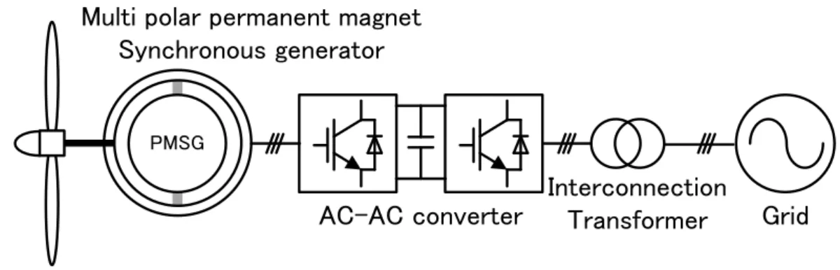
Interconnection
Transformer Grid AC-AC converter
Multi polar permanent magnet Synchronous generator
PMSG
Fig 2.4 Wind turbine PMSG with back-to-back PWM converter
The characteristics of the PWM converter are that the converter utilises active devices at both the generator side for the rectifier and the grid side for the inverter [83].
The advantages of PWM converter are as follows: o The rectifier is controllable, and
o Both rectifier and inverter bridges are composed of active IGBT devices, with the current be able to flow from either the generator to the grid or the grid to the generator.
The major disadvantage of PWM converter topology is:
o The controller is complex and expensive because it requires 12-channel Pulse Width Modulation (PWM) signals for the rectifier and the inverter. For this reason, in a practical application, the control system requires at least two or more Micro-Controller Units (MCU), Digital Signal Processor (DSP), Field Programmable Gate Array (FPGA), etc.
13
A simple topology for wind turbine generation was introduced by [84] and is illustrated in Figure 2.5, which consists of a diode bridge rectifier, with a DC link to an active IGBT inverter.
Interconnection Transformer Grid AC-AC converter
Multipolar permanent magnet Synchronous generator
PMSG
Fig 2.5 Wind turbine generator with diode bridge rectifier
Although this type of converter is simple and reliable, but the power factor of the generator is low. The other problem is that when the output voltage of the rectifier is lower than the grid, power cannot be injected to the grid.
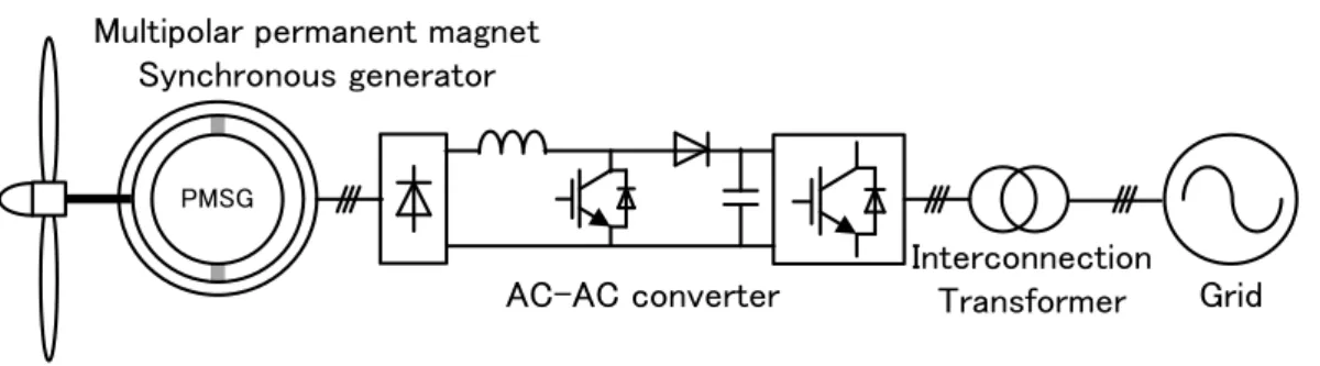
By summarising the topology of back-to-back and diode bridge rectifier, it is possible to insert a boost circuit between the diode rectifier and the inverter, in order to solve the issue of generator power factor, as shown in Figure 2.6. There have been a number of papers describing the inclusion of Power Factor Correction (PFC) with boost chopper circuits, however only a few papers discuss it with the wind turbine controller [68], [69], [85], [86].
14
Interconnection Transformer Grid AC-AC converter
Multipolar permanent magnet Synchronous generator
PMSG
Fig 2.6 Wind turbine generator with diode bridge rectifier and boost chopper circuit
For this topology of converter, operation at relatively low wind speeds is possible due to the inclusion of the boost circuit. The boost chopper circuit can maintain the DC bus link voltage at a constant value. This topology is utilised for the converter in this thesis.
2.2.5
Comparison between Direct Torque Control and Field Oriented ControlDirect torque control (DTC) and field oriented control (FOC) are two of the most commonly applied algorithms for the control of PMSMs. The DTC approach was first developed and presented by I. Takahashi [87]. The basic principle of the DTC approach is that the stator flux linkage and the electromagnetic torque are estimated and compared with their reference values. Based on the control algorithm of mitigating the errors between the reference and estimated values, the reference torque and flux can be achieved by controlling the inverter states. The FOC approach was pioneered by F. Blaschke in 1970s [88]. The FOC approach has been and continues to be a significant factor in PMSMs control, which makes it possible that PMSMs can be controlled as easily as DC machines. In the FOC approach, the dq-axes are rotating at
15
the rotor electrical angular speed with the d-axis aligned with the rotor flux direction. Thus, the flux producing current component, 𝑖𝑑𝑠, and the torque producing current component 𝑖𝑞𝑠, are along the d-axis and q-axis, respectively. Thus, the dq-axes currents can be controlled independently by two closed loop controls in the FOC approach, which indirectly controls the speed and the torque of the PMSMs.
When choosing one control strategy of either DTC or FOC for the generator-side converter control, their merits and drawbacks need to be analyzed and compared according to the operation requirements of the direct-drive PMSG systems. The DTC approach has the advantages that the electromagnetic torque can be changed very fast by changing the reference, and no coordinate transforms and PI controllers are needed which decreases the computational effort. On the other hand, the DTC approach also presents some disadvantages such as: (1) the difficulty to control the torque at very low speed; (2) the high current and torque ripples; and (3) the high noise level at low speed. When it comes to the FOC approach, although its implementation requires large computational effort including PI control and coordinate transformations, it possesses the following merits: (1) fast speed and torque response; (2) outstanding low speed performance; and (3) low current and torque ripples.
For the application of direct-drive PMSG systems, the PMSGs are directly driven by the wind turbine without a gearbox, which means that their operation speeds are always in a relatively low range. Moreover, the torque ripples of the direct-drive PMSGs should be controlled at a low level to decrease the mechanical stresses on the wind turbine. On the basis of the analysis above, the FOC approach was found to be more suitable for the direct-drive PMSG systems than the DTC approach.
16
2.3 System configuration
The variable-speed wind power generation system using a permanent magnet synchronous generator (PMSG), the gearless mechanism which connects the PMSG with the windmill directly without using a speed-increasing gear is realized by adopting the multi-pole PMSG as a generator. The windmill consists of a pitch angle control system. The pitch angle control system is activated beyond the rated wind velocity, and the windmill rotational speed is maintained at the rated windmill speed. Below the rated wind velocity, the windmill rotational speed is controlled in order to maintain the maximum energy conversion efficiency below the rated wind velocity. The converter is connected to the PWM inverter for system interconnection through the DC link condenser. The PWM inverter supplies the power system with the active power obtained from the converter side
2.4 Boost converter scheme
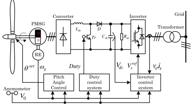
Figure. 2.7 shows the variable speed wind power generation system using diode bridge rectifier and boost converter (boost chopper scheme). It is not possible for the boost chopper scheme to motoring the PMSG, since the diode bridge rectifier limits the direction of current. However, it does not become serious problem, since the motoring mode is not carried out in general wind generator systems. However the diode bridge rectifier cannot control the generator torque, since the armature current of PMSG changes depend on the relationship between induced voltage and DC link
17
voltage. This becomes problem. Then the windmill speed control scheme using the system interconnection inverter was proposed [68], [69]. The proposed scheme controls the windmill speed by adjusting the DC link voltage. The scheme decreases the number of switching devices, and can reduce the size and cost of power conversion system. However, the proposed scheme has the defect that narrows the variable-speed range, since the sufficient generator torque cannot be obtained when the induced voltage is decreases under the low range of wind velocity. Then, in this thesis, the boost chopper circuit is added to improve the variable-speed range. It is possible to control the DC link current regardless of the magnitude of the induced voltage when the boost chopper circuit is added. The generator torque can be controlled by controlling the DC link current in the low range of wind velocity, in which the diode rectification scheme cannot control the generator torque. In short, the variable-speed range from the cut-in wind velocity to the rated wind velocity, which is equivalent to the variable-speed range of PWM converter scheme, is achieved. The PWM converter scheme is explained in 2.5. However the boost chopper scheme needs to add the reactor and switching device for the diode rectification scheme of [68], [69], it has the advantage which can reduce the size and cost of a power converter in comparison with the PWM converter scheme. The inverter controls the generator torque as well as the diode rectification scheme by adjusting the DC link voltage from the wind velocity, which makes the PMSG generate the induced voltage necessary for system interconnection, to the rated wind velocity. The reduction of switching loss and load to the switching device can be reduced by turning off the chopper circuit. And, it is possible to minimize the capacity of switching device by limiting the usage
18
of chopper circuit to the usage in low wind velocity. Under the rated wind velocity, the windmill speed is controlled with two above-mentioned generator torque control schemes. Over the rated wind velocity, the windmill speed is controlled with the pitch angle control system by adjusting the windmill torque. And, the inverter adjusts the DC link voltage and controls the generator torque to maintain the generated output at the rated power of PMSG.
PMSG Anemometer RE g
0V
Converter Inverter Grid
Inverter control system dc C Rdc dc
V
ref sV
v,
si
s Duty control system D Tr dc L Duty Pitch Angle Control set
Transformer N SFig. 2.7 Variable speed wind power generation system using PMSG for boost converter scheme.
2.5 back to back PWM converter scheme
Figure. 2.8 shows the variable speed wind power generation system using back to back PWM converter (PWM converter scheme). The PWM converter controls the
19
windmill speed by adjusting the generator torque. The PWM inverter maintains the DC link voltage to be the constant voltage necessary for system interconnection and keeps the system interconnection. The PWM converter scheme can carry out the high-speed and high-precise generator torque control from the cut-in wind velocity to the rated wind velocity, since the PWM converter scheme can apply the vector control system. Therefore, the frequency characteristics and variable-speed range of the windmill speed control become the benchmark. The similar PWM converter schemes are proposed, and the novelty for scheme itself does not exist. This research utilizes the PWM converter scheme as a comparison object to evaluate the performance of the boost chopper scheme.
a a
i
v ,
ref aV
Converter Converter control system Inverter Grid Inverter control system dc C Rdc dcV
ref sV
v ,
si
s PMSG Anemometer RE g
0V
Pitch Angle Control set
Transformer N SFig. 2.8 Variable speed wind power generation system using PMSG for PWM converter scheme.
20
2.6 Summary
The literature review detailed in this chapter has led to a comprehensive understanding of the concepts relevant to the control of a permanent magnet synchronous generator for wind turbines with grid line connection. Also, this described system configuration of the variable-speed wind power generation system using a permanent magnet synchronous generator for the boost converter scheme and the PWM converter scheme. By this two schemes are utilized for the converter in this thesis.
21
Chapter 3
Assessment with simulation of the
variable speed wind power
generation system
3.1 Modeling method
This chapter described the control strategy and modeling for simulation using Matlab Simulink of the proposed variable-speed wind power generation system using boost converter. Also this paper described the control strategy and modeling of variable-speed wind power generation system using PWM converter. The steady state and transient responses for wind velocity changes were simulated using the Matlab Simulink.
22
3.2 Windmill model
The simulation assumes that wind will pass through the windmill, flowing through the cylindrical tube without interference, as shown in fig.3.1. The velocity diagram of the blade element in the position of radius r assumes fig.3.2. It is assumed that in fig. 3.1, The wind speed accelerates peripheral speed only in𝑤(= 𝑟Ω𝑎,), and that the propeller
wind turbine decelerates the inflow wind speed only in𝑉0𝑎. The variable definitions in
fig. 3.1 and 3.2 are as follows.
0
V
V
0
V
u
V
0
2
V
u
1R
r
dr
Rotor Disk
Fig. 3.1. Annular flow tube
Where, V0:rotor inflow wind speed [m/s], u:wind speed before passing the rotor
23 r w a' r
a
V u 0 1 D L cdirection of wind flow
direction of rotation
W
Fig. 3.2. Velocity triangle
Where, :the rotor angler speed [rad/s], :the blade pitch angle [rad], W:the blade inflow wind speed [m/s], :the inflow angle [rad], :the meeting angle [rad],
L:the lift, D:the drag, a , a’:the interference factor, c:the wind of code [m].
The fore which arises in the blade element caused by wind which passes the propeller wind turbine is defined as lift L and drag D as show in Fig.3.2. The lift dL and drag
dD which arise in the blade element of minimal width dr in the position of radius r are
given in the following equation using the air density𝜌 , lift coefficient 𝑐𝑙, and coefficient 𝑐𝑑 ・・・・・・・・・・・・・・・・・・・・・・・・・・・(3.1) ・・・・・・・・・・・・・・・・・・・・・・・・・・・(3.2) dr cc W dL l 2 2 1 dr cc W dD 2 d 2 1
24
The torques dQ which arises in the blade element of minimal width dr in the position of radius r is a product between radius r and the sum of the rotational direction components of lift dL and drag dD. Therefore, considering the number of blade B, torque dQ is given as.
・・・・・・・・・・・・・・・・・(3.3) In addition, output power is calculated as the product of rotor rotational angle speed 𝛺 and torque dQ.
・・・・・・・・・・・・・・(3.4) In addition, the trust is calculated as.
・・・・・・・・・・・・・・・・・・(3.5) The lift coefficient 𝑐𝑙 and drag coefficient cd are functions of the meeting angle 𝛼. 𝛼 is
calculated using the geometrical relation in the equation.
・・・・・・・・・・・・・・・・・・・・・・・・・・・(3.6) In addition, blade inflow wind speed W and inflow angle 𝜙 can be calculated as follows. ・・・・・・・・・・・・(3.7) ・・・・・・・・・・・・・・・・・・(3.8)
c c
Bcdr r W dQ lsin dcos 2 1 2
c c
Bcdr Ωr W ΩdQ dP lsin dcos 2 1 2
c c
Bcdr W dT lcos dsin 2 1 2
2
2 0 2 2 ' 1 1 a rΩ a V w rΩ u W
1 '
1 tan 0 a rΩ a V w rΩ u
25
Furthermore, torque dQ and thrust dT of the ring division from r to r + dr are given using momentum conservation and Bernoulli’s law in the following equations.
・・・・・・・・・・・・・・・・・・・・・・・・(3.9)
・・・・・・・・・・・・・・・・・・・(3.10) The following equations are obtained, when the equation derived from equations. (3.5) and (3.10) and the equation derived from equations. (3.3) and (3.9) are arranged, by substituting relational expressions of 𝑊 = 𝑢/𝑠𝑖𝑛𝜙 = (𝑟Ω + 𝑤)/𝑐𝑜𝑠𝜙 as explained in Fig.3.2.
・・・・・・・・・・・・・・・・・(3.11)
・・・・・・・・・・・・・・・・・(3.12) The following equation is obtained here, when the variables of 𝑎 = 𝑉𝑜 − 𝑢/𝑉𝑜, 𝑎, =
𝑤/Ω𝑟 , 𝑎𝑛𝑑 𝜎 = 𝐵𝑐/2𝜋𝑟 are defined. 𝜎 is the ratio of local ring division wind receiving area and blade area in the part.
・・・・・・・・・・・・・・・・・・・(3.13)
・・・・・・・・・・・・・・・・・・・(3.14) The following equation is obtained when 𝑥 = 𝑟Ω/𝑉𝑜 the local peripheral speed ratio is
substituted in equations (3.8).
・・・・・・・・・・・・・・・・・・・・・・・・・(3.15) The local output coefficient CP,the local torque coefficient CQ,and the local lift
coefficient CT are given as follows.
rdr
wr u dQ
2
2
rdr
V u
u dT
2
2 0 2 0 sin sin cos 8 d l c c r Bc u u V sin cos cos sin 8 d l c c r Bc rΩ w w
2 sin 4 sin cos 1 d l c c a a cos sin 4 cos sin ' 1 ' cl cd a a '
1
1
tan
a
a
x
26
・・・・・・・・・・・・(3.16)
・・・・・・・・・・(3.17)
・・・・・・・・・・(3.18) Using these local coefficients, the propeller wind turbine output P, the torque Q, and the thrust T are given as.
・・・・・・・・・・・・・・・・・・・(3.19)
・・・・・・・・・・・・・・・・・・・(3.20)
・・・・・・・・・・・・・・・・・・・・・・(3.21) The procedures to calculate propeller wind turbine performance with the derived equations are given below.
(a) The blade of propeller wind turbine is divided into adequate number in a radial direction.
(b) At each division point, the local characteristic value is calculated by the method detailed in the following.
① At the division point position 𝑟, the solution of the nonlinear simultaneous equation composed of equations. (3.13),(3.14),and (3.15) is obtained Concretely, 𝑎, 𝑎′, and 𝜙 are calculated by repeat calculation using the Newton
method. B,c,𝜃,V0,and Ω in the nonlinear simultaneous equation are the
variables given as a condition. cl,cd are a function of 𝛼,and the table for 𝛼
is prepared. equation. (3.6).
② CP,CQ,CT in division point position 𝑟 are calculated with equations. (3.16),
(3.17), and (3.18).
a
a
x r rdr V wr rdr u r rdr V dQ CQ 4 '1 2 5 . 0 2 2 2 5 . 0 02 2 0
a
a
rdr V u V rdr u r rdr V dT CT 4 1 2 5 . 0 2 2 2 5 . 0 02 0 2 0
R P rdr C V P 0 3 0 2 5 . 0
V RCQ r dr Q 0 2 2 0 2 5 . 0
V R CT rdr T 0 2 0 2 5 . 0
3
2 0 3 0 1 ' 4 2 5 . 0 2 2 2 5 . 0 V rdr a a x wr rdr u Ω r rdr V ΩdQ CP
27
(c) After obtaining the characteristic value (CP,CQ,CT) at each division point, the
propeller wind turbine performance (P,Q,T) is calculated with integral computation of equations. (3.19), (3.20), and (3.21).
Fig. 3.3 shows the wind shape of wind turbine. The wind turbine shape is designed for wind turbine power generation of 300 [W] rated power, rotor diameter 1.52 [m]. Table 4.1 shows the width of code [m], the angle of twist [degree], the profile of NACA in the position of distance from the rotor center to the radial direction. The app. Table 4.1 shows the data of lift coefficient and drag coefficient for meeting angle [degree] of the profile of NACA in table 4.1. The calculation program for wind turbine performance calculation based on the Rankine-Froude actuator disc theory is made with Matlab. The program made on Matlab can be referred to on Matlab Simulink as S-function. Therefore, it can be used as a propeller wind turbine model to calculate the wind turbine torque generation.
Fig. 3.3. Wind turbine blade shape model
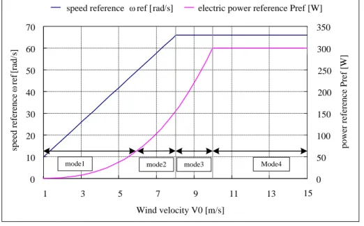
Fig. 3.4 shows the wind turbine speed reference and electric power reference to keep maximum conversion factor. The limited value ωgmax of windmill speed is set at 105%
] [m c 0 0 center of wind turbine ] [m r width of code
distance from center of rotor


![Fig 4.6. The angle of attack of 0 [deg] of the wind velocity distribution Inflow direction](https://thumb-ap.123doks.com/thumbv2/123deta/6497064.1125086/125.892.186.781.645.966/fig-angle-attack-wind-velocity-distribution-inflow-direction.webp)
![Fig 4.10. The angle of attack of -10 [deg] of the wind velocity distribution Inflow direction](https://thumb-ap.123doks.com/thumbv2/123deta/6497064.1125086/127.892.195.771.617.944/fig-angle-attack-wind-velocity-distribution-inflow-direction.webp)
![Fig 4.11. The angle of attack of -10 [deg] of the pressure distribution](https://thumb-ap.123doks.com/thumbv2/123deta/6497064.1125086/128.892.191.782.199.523/fig-angle-attack-deg-pressure-distribution.webp)
