Pyrolysis of Sugarcane Bagasse and Polyvinyl Chloride in Superheated Steam
Atmosphere
Abdul Muaz Hapipi
Graduate School of Environmental and Life Science, Okayama University
March 2018
i
Table of Contents
Chapter 1 General introduction ... 1
1.1 Organic waste ... 1
1.2 Pyrolysis process ... 1
1.3 Sugarcane bagasse carbonization... 2
1.4 Polyvinyl Chloride (PVC) dechlorination ... 3
1.5 Superheated steam ... 4
1.6 Research objectives ... 5
1.7 References ... 6
Chapter 2 Carbonization of sugarcane bagasse and heat transfer property by pyrolysis in superheated steam and nitrogen atmospheres ... 13
2.1 Introduction ... 13
2.2 Experimental ... 15
2.2.1 Method ... 15
2.2.2 Characterization of bagasse ... 18
2.2.3 Sample preparation ... 18
2.3 Results and discussion ... 20
2.3.1 Char yield ... 20
2.3.2 Elemental analysis ... 22
2.3.3 Higher heating value (HHV) ... 25
2.3.4 Carbon losing rate... 26
2.3.5 Calculation model for heat transfer behavior of superheatedsteam and nitrogen in bagasse pyrolysis ... 28
2.3.6 Setting of emissivity, ԑ
12... 29
2.3.7 Comparison of sample temperature change between experimental and calculated values ... 30
2.4 Conclusions ... 37
2.5 References ... 38
ii
Chapter 3 Dechlorination of polyvinyl chloride under superheated
steam ... 43
3.1 Introduction ... 43
3.2 Experimental ... 44
3.3 Results and discussion ... 47
3.3.1 Effect of dechlorination temperature and residence time .... 47
3.3.2 Effect of solid acid catalysts ... 49
3.3.3 Effect of alkali adsorbent ... 50
3.3.4 Effect of metal oxides loading amount ... 51
3.3.5 Effect of metal oxides supported adsorbents... 52
3.3.6 Effect of ZnO loading amount ... 55
3.3.7 Effect of dechlorination atmospheres ... 57
3.3.8 Comparison of dechlorination ability and solid yield ... 60
3.4 Conclusions ... 62
3.5 References ... 63
Chapter 4 Summary ... 69
Acknowledgement ... 72
1
Chapter 1 General introduction
1.1 Organic waste
The main forms of organic waste are household food waste, agricultural waste, human and animal waste and industrial waste [1-2]. Organic waste is considered as an important source of energy because of the presence of the organic compounds. Organic waste can be converted into energy such as solid and liquid fuels which are renewable and environmentally friendly [3-8]. Dumping and landfilling normally used for the treatment of household and industrial wastes while agricultural and human and animal wastes were treated by biological treatment [9]. The other method for treating these wastes are thermal treatment such as incineration, gasification and pyrolysis [10].
1.2 Pyrolysis process
Pyrolysis, the organic (carbon-based) materials decomposes chemically through the application of heat in the absence of oxygen or low oxygen level. The word is derived from the Greek words “pyro” meaning fire and “lysis” meaning decomposition. There are three types of pyrolysis depending on the operating conditions: slow pyrolysis or carbonization (550-950 K), intermediate pyrolysis (850-1250 K) and fast pyrolysis (1050-1300 K) [11]. The main goal for slow pyrolysis or carbonization is production of charcoal with lower moisture content and higher energy content while the main target products of intermediate and fast pyrolysis are bio-oil [11-16]. Pyrolysis products can be used as substitute charcoal or as industrial fuel [1, 17]. In pyrolysis process, product yield and quality can be influenced by many factors such as: catalysts, contact time,
2
feed pretreatment, feed material, heating rate, particle size, moisture content, pressure, reactor geometry, temperature, residence time, reagents and treatment atmosphere [18].
1.3 Sugarcane bagasse carbonization
Sugarcane is used as a feedstock for ethanol and sugar production. Sugarcane bagasse is the residual material derived from sugarcane after extracting cane juice.
Bagasse is discarded as agricultural waste or burned for energy supply in sugar and ethanol mill. Bagasse is a lignocellulosic compound which contains cellulose, hemicellulose and lignin. The decomposition of these components occurs at different temperatures during the pyrolysis [19]. Hemicellulose typically decomposes in the range of 433- 633 K, while cellulose degrades at the higher temperature range of 513-663 K and lignin at 550-770 K. Biochar, bio-oil and gaseous products are the main product that can be obtain during the pyrolysis at different operating conditions. Biochar mainly obtained during carbonization and can be use as adsorbent (activated carbon), catalyst support, fuel feedstock, and soil fertilizer [20]. The bio-oil is the main product of fast pyrolysis, which has a great potential to be used in the equipment such as static engines, turbines, burners, boilers, and diesel engines. Gaseous products are obtained mainly at higher temperatures, and can be consumed to generate heat for pyrolysis reactor, to run a gas turbine for electricity generation, and to produce syngas that can be converted into gasoline and diesel through Fischer-Tropsch process. The hydrogen obtained from pyrolysis can be applied in hydrotreating processes, ammonia production, and in fuel cells [20].
3
1.4 Polyvinyl Chloride (PVC) dechlorination
Polyvinyl chlorine (PVC) is one the widely used plastic polymer after polyethene (PE) [21-23]. PVC is widely used in use in building, transport, packaging, electrical/electronic components and healthcare applications [11]. PVC is obtain from the polymerization of vinyl chloride monomer (VCM) with general chemical formula:
-(CH2CHCl)n- as shown in Fig. 1-1. The disposal of PVC become a major environmental issue because it is non-biodegradable and contain chlorine compound which could be released during waste treatment and cause the corrosion of the boiler and other environmental problems [3,7, 13-30]. Usually PVC waste was treated using thermal degradations such as pyrolysis, gasification and combustion. The main objective for the PVC treatment is to remove the chlorine because it will cause the corrosion of the treatment plant and other environmental problems. The degradation of PVC under pyrolytic conditions can be divided into two stages [31-33]. In the first stage at temperature around 600 K, the degradation is mostly by dehydrochlorination and followed by the formation of polyene, and others aromatic products. The second stage starts at temperature around 750 K with the degradation of polyene leading to the evolution of aromatic compounds such as benzene, toluene, naphthalene, indene, and various chlorobenzenes. Stepwise pyrolysis, catalytic pyrolysis and pyrolysis with adsorbent were the main pyrolysis method used [34-35]. During stepwise pyrolysis, maximum chlorine released from PVC at 573 K [36-37]. In catalytic pyrolysis, solid acid catalysts and metal oxides can increase the chlorine removal rate and some of metal oxide can act as adsorbent which will suppress the HCl formation [34, 38]. The pyrolysis with adsorbents of catalysts usually carried out with the alkali compound such
4
as KOH, NaOH, Ca(OH)2, CaO, Na2CO3 etc. The addition of these adsorbents will trap evolved HCl in the solid sample by physical or chemical adsorption [34].
Fig. 1-1 Polymerization of vinyl chloride to PVC.
1.5 Superheated steam
Superheated steam is produced by heating saturated steam to the temperatures higher than the boiling point of water [39-42]. Superheated steam usually used in the food, medical, and other industries where cleaning, disinfection, and drying play a crucial role.
During the drying process, superheated steam can be act both as dry hot gas and as steam [43]. Compared with hot air and inert gas at the same temperature, this superheated steam has very unique properties such as, 1) high temperature at normal temperature, 2) Extremely high thermal conductivity, 3) a higher heating rate due to radiative heating in addition to convective heating as illustrated in Fig. 1-2, and 4) in low oxygen conditions [43-49]. The only problem of using superheated steam is that a large amount of energy needed to generate superheated steam compared with hot air or gas at the same temperature. The only way to solve this problem is to make use of the extra energy for superheated steam generation at works such as steelmaking plant etc.
5
Fig. 1-2 Superheated steam drying properties.
1.6 Research objectives
A considerable amount of research has been conducted in the area of organic waste pyrolysis process using inert gas such as nitrogen. Less attention has been paid to the others pyrolysis atmospheres such as superheated steam and CO2. Superheated steam is produced by heating saturated steam to the temperature higher than boiling point.
Compared with hot air and inert gas at the same temperature, this superheated steam has very unique properties such as, 1) a higher heating rate due to radiative heating in addition to convective heating, 2) higher specific enthalpy 3. Thus, using superheated steam in the pyrolysis atmosphere may lead to substantial energy saving if no oxidation occurs [50-51]. The main purposes of the research are to study the pyrolysis behavior of two types of organic wastes with, sugarcane bagasse and polyvinyl chloride (PVC) under superheated steam atmosphere. In the case of sugarcane bagasse, the effect of superheated steam on the yield of carbonization products and the heat transfer properties steam were investigated. In the case of low temperature pyrolysis of PVC, effect of pyrolysis atmosphere such as superheated steam and nitrogen on the dechlorination of PVC were investigated. Furthermore, the effects of addition of chemicals, adsorbents and catalysts such as solid acid catalysts, alkali adsorbents and metal oxides on the dechlorination of PVC were investigated.
6
1.7 References
(1) I. F. Titiladunayo, A. G. McDonald, O. P. Fapetu, “Effect of temperature on biochar product yield from selected lignocellulosic biomass in a pyrolysis process,” Waste Biomass Valor, 3 (3), 311-318 (2012)
(2) W. Kwaspinski, C. M. P. Byrne, E. Kyyachko, “Biochar from biomass and waste,”
Waste Biomass Valor, 1(2), 177-189 (2010)
(3) J. Lu, S. Ma, and J. Gao, “Study on the pressurized hydrolysis dechlorination of PVC,” Energy Fuels, 16 (5), 1251–1255 (2002)
(4) A. Castro, “Kinetic study of thermal de-chlorination of PVC-containing waste,”
WASTES: Solutions, Treatments and Opportunities, 1st International Conference 2011
(5) M. Sarker, M. M. Rashid, “Catalytic Conversion of Low Density Polyethylene and Polyvinyl Chloride Mixture into Fuel using Al2O3,” IJMMT, 1 (2), 8–16 (2013) (6) M. Sarker, M. M. Rashid, “Thermal and Catalytic Treatment of PVC and HDPE
Mixture to Fuel using NaHCO3,” IJESTR, 1 (1), 20–27 (2013)
(7) Q. Zhou, C. Tang, Y. Z. Wang, L. Zheng, “Catalytic degradation and dechlorination of PVC-containing mixed plastics via Al-Mg composite oxide catalysts,” Fuel, 83 (13), 1727–1732 (2004)
(8) M. A. Keane, “Review Catalytic conversion of waste plastics: focus on waste PVC,”
J. Chem. Technol. Biotechnol, 82, 787–795 (2007)
(9) T. Li, P. Zhao, M. Lei, Z. Li, “Understanding Hydrothermal Dechlorination of PVC by Focusing on the Operating Conditions and Hydrochar Characteristics,” Appl. Sci., 7 (3), 256 (2017)
7
(10) M. Inyang, B. Gao, P. Pullammanappallil, W. Ding, A. R. Zimmerman, A.R,
“Biochar from anaerobically digested sugarcane bagasse,” Bioresource Technology, 101, 8868-8872 (2010)
(11) C. G. Mothe, I. C. de Miranda, “Characterization of sugarcane and coconut fibers by thermal analysis and FTIR,” J. Therm. Anal. Calorim, 97, 661-665 (2009) (12) D. K. Barnes, F. Galgani, R. C. Thompson, M. Barlaz. 2009, “Accumulation and
fragmentation of plastic debris in global environments,” Philos Trans R Soc Lond B Biol Sci., 1985-1998 (2009)
(13) K. Li, S. W. Lee, G. Yuan, J. Lei, S. Lin, P. Weerachanchai, Y. Yang, J. Wang,
“Investigation into the Catalytic Activity of Microporous and Mesoporous Catalysts in the Pyrolysis of Waste Polyethylene and Polypropylene Mixture,”
Energies, 9 (6), 431 (2016)
(14) T. Bhaskar, M. A. Uddin, J. Kaneko, T. Kusaba, T. Matsui, A. Muto, Y. Sakata, K.
Murata, “Liquefaction of mixed plastics containing PVC and dechlorination by calcium-based sorbent,” Energy Fuels, 17 (1), 75–80 (2003)
(15) A. Castro, D. Soares, C. Vilarinho, F. Castro, “Kinetics of thermal de-chlorination of PVC under pyrolytic conditions,” Waste Manag, 32 (5), 847–851 (2012)
(16) Y. Kakuta, K. Hirano, M. Sugano, K. Mashimo, “Study on chlorine removal from mixture of waste plastics,” Waste Manag, 28 (3), 615–621 (2008)
(17) P. Zhao, T. Li, W. Yan, L. Yuan, “Dechlorination of PVC wastes by hydrothermal treatment using alkaline additives,” Environ Technol., 1–9 (2017)
(18) N. Lingaiah, M. A. Uddin, A. Muto, T. Imai, Y. Sakata, “Removal of organic chlorine compounds by catalytic dehydrochlorination for the refinement of municipal waste plastic derived oil,” Fuel, 80 (13), 1901–1905 (2001)
8
(19) T. J. Hugo, “Pyrolysis of sugarcane bagasse,” Thesis (MScEng (Process Engineering)), University of Stellenbosch, (2010)
(20) E. V. Goncalves, F. L. Seixas, L. R. S. S. Santana, M. H. N. O. Scaliante, M. L.
Gimenes, “Economic trends for temperature of sugarcane bagasse pyrolysis,” Can J Chem Eng, 95 (7), 1269-1279 (2017)
(21) T. Kameda, G. Grause, T. Yoshioka, “Chemical modification of flexible poly(vinyl chloride) by nucleophilic substitution,” Society of Plastics Engineers, (2010) (22) C. L. Beyler, M. M. Hirschler, “Thermal decomposition of polymers,” SFPE
Handbook of Fire Protection Engineering, 2 (7), 111-131 (2002)
(23) Y. Sato, K. Kato, Y. Takeshita, K. Takahashi, S. Nishi, “Decomposition of Polyvinylchloride using Supercritical Water,” Jpn. J. Appl. Phys., 37 (11), 6270-6271 (1998)
(25) J. A. Onwudili and P. T. Williams, “Hydrothermal catalytic gasification of municipal solid waste,” Energy Fuels, 21 (6), 3676–3683 (2007)
(25) F. Osada, J. Yana, “Deplasticization and dechlorination of flexible polyvinyl chloride in NaOH solution by microwave heating,” J. Mater. Cycles Waste Manage., 12 (3) , 245–253 (2010)
(26) T. Kameda, C. Shoji, S. Fukushima, G. Grause, T. Yoshioka, “Removal of chloride from ethylene glycol solution using alumina/zeolite membrane as a physical boundary between the organic and aqueous phases,” J. Mater. Cycles Waste Manage., 15 (3), 404–408 (2013)
(27) S. Shin, T. Yoshioka, A. Okuwaki, “Dehydrochlorination Behavior of Flexible PVC Pellets in NaOH Solutions at Elevated Temperature,” J. Appl. Polym. Sci. , 2171–2177 (1997)
9
(28) M. A. Uddin, Y. Sakata, Y. Shiraga, A. Muto, K. Murata, “Dechlorination of Chlorine Compounds in Poly(vinyl chloride) Mixed Plastics Derived Oil by Solid Sorbents.,” Ind. Eng. Chem. Res., 38 (4), 1406–1410 (1999)
(29) M. Sarker, M. M. Rashid, “Polyvinyl Chloride ( PVC ) Waste Plastic Treatment Using Zinc Oxide ( Zno ) With Activated Carbon And Produced Hydrocarbon Fuel For Petroleum Refinery,” Int J Eng Sci., 1 (8), 29–41 (2012)
(30) R. Zevenhoven, E. P. Axelsen, M. Hupa, “Pyrolysis of waste-derived fuel mixtures containing PVC,” Fuel, 81, 507-510 (2002)
(31) G. Sivalingam, R. Karthik, G. Madras, “Effect of metal oxides on thermal degradation of poly(vinyl acetate) and poly(vinyl chloride) and theirs blends,” Ind.
Eng. Chem. Res., 42 (16), 3647-3653 (2003)
(32) S. Shin, T. Yoshioka, A. Okuwaki, “Dehydrochlorination behavior of flexible PVC pellets in NaOH solutions at elevated temperature,” J. Appl. Polym. Sci., 67, 2171-2177 (1998)
(33) K. German, E. Pawlikowska, K. Kulesza, “Chemical adsorption of liquid organochlorine compounds as a method of purification of pyrolytic oil,” Polimery, 56, 67-69 (2010)
(34) K. Sharma, A. Vyas, S. K. Singh, “Conversion of waste PVC into liquid fuel,”
IJTEEE, 3 (4), 2347-4289 (2015)
(35) T. Zao, Q. Zhou, X. Jiang, A. Du, Y. Wang, “Dehydrochlorination of polyvinyl chloride in basic ionic liquids,” The 5th ISFR , October 11-14, (2009)
10
(36) M. Kappes, G. F. Porzio, V. Colla, M. Vannucchi, W. Krumm, “Steam gasification process of chlorine-rich shredder granules: Experiments and flow-sheeting modelling for process evaluation and scale up,” Chem Eng Trans., 35, 1321-1326 (2013)
(37) M. C. Gupta, S. G. Viswanath, “Role of metal oxides in the thermal degradation of poly(vinyl chloride),” Ind. Eng. Chem. Res. , 37 (7), 2707-2702 (1998)
(38) A. Ballistreri, S. Foti, P. Maravigna, G. Montaudo, E. Scamporrino, “Effect of metal oxides on the evolution of aromatic hydrocarbons in the thermal decomposition of PVC,” J. Polym. Sci. A, 18, 3101-3110 (1980)
(39) W. Ma, G. Hoffmann, M. Schirmer, G. Chen, V. S. Rotter, “Chlorine characterization and thermal behavior in MSW and RDF,” J J. Hazard. Mater., 178 (1-3), 489–498 (2010)
(40) N. Maruyama, Y. Ichihashi, D. Tanaka, T. Shimizu, “ Environmental Evaluation of Material Resource Recycle System from High Water Content Waste to Solid Fuel using Superheated Steam,” 5th Int Energy Convers. Eng. Conf. Exhib. 7, 363-369(2007)
(41) T. Iwasaki, S. Mizuhashi, S.Watano, T. Akachi, H. Yoshida, “ Recovery of Valuables from Wood Waste by Superheated Steam Carbonization,” Asian Pacific Confederation of Chemical Engineers Congress program and abstracts, 1-9 (2005) (42) O. Yamada, “ Generation of hydrogen gas by reforming biomass with superheated
steam,” Thin Solid Films. 509, 207-211 (2006)
11
(43) E. K. Bahrin, A. S. Baharuddin, M. F. Ibrahim, M. N. Abdul Razak, A. Sulaiman,
“ Physicochemical property changes and enzymatic hydrolysis enhancement of oil palm empty fruit bunches treated with superheated steam,” BioResources 7, 1784-1801 (2012)
(44) T. Amatsubo, Y. Hagura, “ Heat transfer characteristics of superheated steam combined with far infrared heating,” Food Sci. Technol. Res., 11, 363-368 (2005)
(45) A. ISA, Y. Hagura, “ Investigation of carbonization energy for waste biomass in superheated steam combined with far-infrared heating,” Japan J Food Eng., 12, 39-45 (2011)
(46) W. H. Chen, S. C. Ye, H. K. Sheen, “ Hydrothermal carbonization of sugarcane bagasse via wet torrefaction in association with microwave heating,” Bioresour.
Technol., 118, 195-203 (2012)
(47) M. Nan, A. S. Baharuddin, E. K. Bahrin, A. Sulaiman, M. N. Naim, R. Zakaria,
“Enzymatic saccharification of oil palm mesocarp fiber (OPMF) treated with superheated steam,” BioResources, 8, 1320-1331 (2013)
(48) N. Maruyama, D. Tanaka, M. Tamada, T. Shimizu, M. Hirota, M, “ Waste recycling using superheated steam and its environmental evaluation,” 7th International Energy Conversion Engineering Conference, Denver, Colorado, August 2-5 (2009)
(49) N. Maruyama, D. Tanaka, M. Tamada, T. Shimizu, A. K. Gupta, A.K,
“ Experimental investigation to process high water content waste to solid fuel using superheated steam,” The Second International Energy 2030 Conference 136-137 (2008)
12
(50) H. Suda, M. A. Uddin, Y. Kato, “Chlorine removal from incinerator bottom ash by superheated steam,” Fuel, 184, 753-760 (2016)
(51) T. Hase, M. A. Uddin, Y. Kato, M. Fukui, “Drying and organic chlorine thermal decomposition behavior of municipal solid waste using superheated steam,” Jpn. J.
Mater. Cycles Waste Manage. 25, 16-24 (2014)
13
Chapter 2 Carbonization of sugarcane bagasse and heat transfer property by pyrolysis in superheated steam and nitrogen atmospheres
2.1 Introduction
Recently, the utilization of biomass resources has gained many interests due to the depletion of fossil fuel. Biomass is also one of the organic wastes which are produced in agriculture and forestry [1]. Biomass waste can be converted into biofuels which are renewable and environmentally friendly [1, 2]. Carbon, hydrogen, oxygen and nitrogen are the most common substances in biomass [3]. The main elemental composition of woody biomass is carbon (52.0 wt%), oxygen (40.5 wt%), hydrogen (6.3 wt%), and nitrogen (0.4 wt%) [3]. Meanwhile, proximate analysis of that woody biomass contains volatile matter (80.0 wt%), fixed carbon (19.4 wt%), and ash (0.65 wt%) [4-7].
Physical, biological and thermochemical processes are normally being used to convert biomass to energy [4]. Grinding, drying, filtration, pressing, extraction, and briquetting are the example of physical process pretreatment before being used in another process. Biological process includes anaerobic digestion and fermentation.
Thermochemical process can be divided into gasification, pyrolysis and combustion [5, 8]. Pyrolysis is a process which converts biomass into liquid (tar and other organics), solid (charcoal) [9, 10], and gaseous products (H2, CO, CO2, CH4, C2H4, C2H6) by heating biomass in the absence of oxygen or very low oxygen level [4]. There are three types of biomass pyrolysis depending on the operating conditions: slow pyrolysis or carbonization (550-950 K), intermediate pyrolysis (850-1250 K) and fast pyrolysis
14
(1050-1300 K) [11]. The main goal for slow pyrolysis or carbonization is charcoal with lower moisture content and higher energy content while the main goal for intermediate and fast pyrolysis are bio-oil [4, 11-17]. Pyrolysis products can be used as substitute charcoal or as industrial fuel [1, 18]. In biomass pyrolysis, product yield and quality can be influenced by many factors such as: catalysts, contact time, feed pretreatment, feed material, heating rate, particle size, moisture content, pressure, reactor geometry, temperature, residence time, and reagents [19]. A considerable amount of research has been conducted to the pyrolysis process using inert gas such as nitrogen. Less attention has been paid to the others pyrolysis atmospheres such as superheated steam.
Superheated steam is produced by heating saturated steam to the temperature higher than boiling point [20-23]. Compared with hot air and inert gas at the same temperature, this superheated steam has very unique properties such as, 1) a higher heating rate due to radiative heating in addition to convective heating, 2) higher specific enthalpy [20, 24-29]. Thus, using superheated steam in the pyrolysis atmosphere may lead to substantial energy saving if no biomass oxidation occurs.
The main purpose of this research is to investigate the carbonization of sugarcane bagasse and heating property via superheated steam and nitrogen gas heating.
Sugarcane bagasse was used as a material of the organic wastes in this research because of their high thermal value when dried [30]. Sugarcane bagasse is the residual material derived from sugarcane after extracting cane juice. Bagasse is carbon-rich biomass and suitable for biochar production. One of the possible ways to obtain high thermal value sugarcane bagasse is to convert to biochar by carbonization process. Some studies have been devoted to the problems of sugarcane bagasse hydrolysis to obtain sugar and furfural [31, 32], but less attention has been paid to the sugarcane bagasse carbonization
15
using superheated steam. In this research, the temperature increasing behavior and carbonization of the sugarcane bagasse under superheated steam and nitrogen atmosphere has been investigated and the results of both methods were compared.
2.2 Experimental 2.2.1 Method
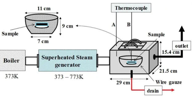
Carbonization of the bagasse was conducted using the superheated steam device (Dai-ichi High Frequency Co. Ltd., Hi-HEATER 2005S) as shown in Fig. 2-1. The equipment consists of a boiler, a superheated steam generator, and a reaction chamber.
Steam was produced from the boiler and then the temperature was risen to the setting temperature using superheated steam generator. Two thermocouples (A, B) were attached to the reaction chamber (A) and sample (B) to measure chamber and sample temperature.
First, superheated steam temperature, Tshs [K], in the chamber was set to the experimental temperature (491,541, 579, 617, 650, and 702 K). When the chamber temperature became almost constant, 5 g of the dried pellet as described in 2.3 was inserted in a sample basket, and placed in the chamber. Carbonization was carried out for 5, 10, 15, 20, 25 and 30 minutes at all temperatures. The flow rate of superheated steam in the reaction chamber was fixed to 10 kg/h. After the carbonization finished, sample was cooled down below 343 K. Then, the sample was dried at 383 K for 24 h to remove condensed water trapped in the carbonized residue.
On the other hand, carbonization via nitrogen gas was carried out by using the electric furnace (As One Co. Ltd., TMF-500N) shown in Fig. 2-2. The reaction tube and sample temperatures were measured by two thermocouples (A, B) attached on the outer
16
wall of the reaction tube (A) and sample (B), respectively. The reaction tube temperature, TN2 [K], was set to be equal to Tshs [K] for superheated steam such as 491, 541, 579, 617, 650 and 702 K. The effect of carbonization time for nitrogen heating was studied at TN2 = 617 K (Tm=592 K) for 5-30 min. Nitrogen flow rate in the reaction chamber was fixed to 6.0 kg/h. Sample preparation and experimental setting is the same as superheated steam carbonization.
The relationship between the chamber (superheated steam) or reaction tube (nitrogen gas) and sample temperatures at 30 min is shown in Table 2-1. The sample temperature, Tm [K], in the reaction tube of Fig. 2-2 became finally lower than that of superheated steam in Fig. 2-1.
Fig. 2-1 Schematic diagram of superheated steam device.
17
Fig. 2-2 Schematic diagram of electric furnace.
Table 2-1 Temperatures of chamber or reaction tube and sample for superheated steam and nitrogen heating practices at 30 min.
Superheated steam Nitrogen gas
Chamber temperature,
Tshs [K]
Sample temperature,
Tm [K]
Reaction tube temperature,
TN2 [K]
Sample temperature,
Tm [K]
491 490 491 471
541 539 541 503
579 576 579 554
617 616 617 592
650 647 650 615
702 701 702 663
18
2.2.2 Characterization of bagasse
The remaining of the sample after carbonization was measured for the char yield. The char yield was calculated using the following equation:
Char yield [wt%] = (Sample residue weight after carbonization [g])/ (Solid
weight before carbonization [g]) ×100 (1) Elemental analysis of the sample was done before and after carbonization. Carbon, C
[wt%], hydrogen, H [wt%] nitrogen, N [wt%] and sulfur, S [wt%] contents were analyzed by CHNS analyzer (Perkin Elmer series, 2004 II) for the ultimate analysis.
While oxygen, O, [wt%] content was calculated from the equation below.
O = 100 – (C + H + N + S) (2)
Higher heating value, HHV [kJ/kg], of the sample can be calculated with ultimate analysis data and the equations can be obtained as follows [33]:
HHV = 343.08C + 424.92H + 261.98N + 27.76O (3)
Carbon losing rate was calculated using the following equation:
Carbon losing rate [wt%] = {(WINITCINIT – WFINCFIN) / (WINITCINIT)} ×100 (4) where WINIT and CINIT are the initial weight [g] and carbon content [wt%] of
sugarcane bagasse, respectively, while WFIN and CFIN are the weight [g] and carbon content [wt%] of the sample after carbonization, respectively.
2.2.3 Sample preparation
Sugarcane bagasse from Okinawa, Japan, was selected as a raw material in this study.
Tables 2-2 and 2-3 show the ultimate and proximate analyses [34], respectively. Carbon, hydrogen, nitrogen and oxygen were recognized from the ultimate analysis. The fixed carbon became 20.4 wt% and HHV was calculated from Eq. (3) as shown in Table 2-3.
19
In order to make it easy to put it in the sample basket, the sample was pelletized. After grinded in a mixer, the resulting pulverized bagasse was dried in a dryer at temperature of 383 K for 24 h to remove the moisture content from the sample. It was compressed using a hydraulic presser to obtain the pellet form of the bagasse. The pellets were also dried in a dryer at temperature of 383 K for 24 h prior to the experiment. Photographic image of the pellet used for the experiment is shown in Fig. 2-3.
Table 2-2 Ultimate analysis of raw material (dry basis).
C [wt%] H [wt%] N [wt%] S [wt%] O [wt%]
46.0 6.2 0.4 0.9 46.5
Table 2-3 Proximate analysis of raw material.
Volatile matter [wt%]
Fixed carbon [wt%]
Ash [wt%]
HHV [MJ/kg]
78.7 20.4 0.9 19.8
Fig. 2-3 Photographic image of the sample pellet.
20
2.3 Results and discussion 2.3.1 Char yield
Figure 2-4 shows the effect of carbonization time on the char yield in superheated steam and nitrogen gas. Both char yields in superheated steam and nitrogen gas atmospheres decreased at the first 10 to 15 minutes and became constant within 25-30 minutes of carbonization.
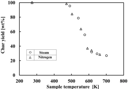
The relationship between the char yield and carbonization temperature at carbonization time of 30 min is shown in Fig. 2-5. The char yield decreased with the increasing temperature and there was no different tendency between superheated steam and nitrogen gas. This suggests that the oxidation rate of carbon by superheated steam is very small and negligible.
Fig. 2-4 Temporal change in char yield for superheated steam and nitrogen gas.
21
Fig. 2-5 Relationship between char yield and sample temperature at 30 min of carbonization.
A possibility of carbon oxidation by superheated steam was examined by thermodynamic equilibrium [34]. The relationship between Gibbs free energy, ΔG [J/mol], of C + H2O→CO + H2 and (1/2) C + H2O→ (1/2) CO2 + H2 and temperature with PH2/PH2O as a parameter is shown in Fig. 2-6. It was found that ΔG<0, that is, the oxidation reaction of carbon may occur according to temperature and PH2/PH2O. For example, when the char yield in Fig. 2-4 reduced to 25wt % at Tm=701 K at 5 min and the sample carbon content was 60.8 wt.% as described later in Table 2-5, PH2/PH2O of C + H2O→CO + H2 and (1/2) C + H2O→ (1/2) CO2 + H2 were calculated as 0.003 and 0.006. Thus, from Fig. 6, these ΔG values became -3x10⁴ and -4x10⁴ J/mol, respectively, and the oxidation of carbon was possible thermochemically. In conclusion, the oxidation rate of carbon by superheated steam was negligible small in this experiment.
22
Fig. 2-6 Relationship between Gibbs free energy change of water gas reaction and temperature in superheated steam.
2.3.2 Elemental analysis
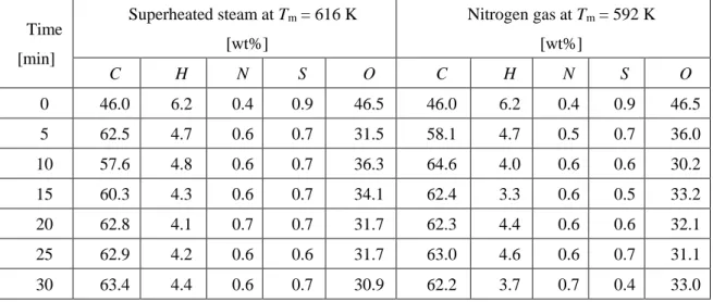
Table 2-4 presents an example of temporal change in the sample composition at Tm of 616 K for the treatment in superheated steam and 592 K for nitrogen, respectively.
There was only a small difference in the char composition between both carbonization atmospheres at each carbonization time. The temperature rising in superheated steam was unstable at the first 10 minutes of carbonization which resulted in the increasing and decreasing in the carbon content. The effect of sample temperature on the composition at 30 min of carbonization time is shown in Table 2-5. The increasing carbonization temperature resulted in the increase of carbon contents and decrease of oxygen contents [35], however the carbon content decreased and the oxygen content increased at the sample temperature of 701 K in superheated steam and 663 K in
23
nitrogen gas. It might be due to secondary cracking of the char into gaseous products [36, 37].
Table 2-4 An example of temporal change in sample composition for superheated steam and nitrogen heating practices.
Time [min]
Superheated steam at Tm = 616 K [wt%]
Nitrogen gas at Tm = 592 K [wt%]
C H N S O C H N S O
0 46.0 6.2 0.4 0.9 46.5 46.0 6.2 0.4 0.9 46.5
5 62.5 4.7 0.6 0.7 31.5 58.1 4.7 0.5 0.7 36.0
10 57.6 4.8 0.6 0.7 36.3 64.6 4.0 0.6 0.6 30.2
15 60.3 4.3 0.6 0.7 34.1 62.4 3.3 0.6 0.5 33.2
20 62.8 4.1 0.7 0.7 31.7 62.3 4.4 0.6 0.6 32.1
25 62.9 4.2 0.6 0.6 31.7 63.0 4.6 0.6 0.7 31.1
30 63.4 4.4 0.6 0.7 30.9 62.2 3.7 0.7 0.4 33.0
Table 2-5 Effect of sample temperature on product composition at 30 min of carbonization time.
Superheated steam [wt%] Nitrogen gas [wt%]
Sample temperature
[K]
C H N S O
Sample temperature
[K]
C H N S O
Raw
material 46.0 6.2 0.4 0.9 46.5
Raw
material 46.0 6.2 0.4 0.9 46.5
490 47.3 6.2 0.4 0.9 45.2 471 47.0 6.0 0.3 0.9 45.8
539 50.1 6.0 0.4 0.9 42.6 503 48.6 5.7 0.4 0.9 44.3
576 54.5 5.7 0.5 0.7 38.6 554 52.8 5.5 0.5 0.8 40.4
616 63.4 4.4 0.6 0.7 30.9 592 62.2 2.7 0.7 0.4 34.0
647 64.1 4.0 0.6 0.6 30.7 615 65.8 4.0 0.6 0.6 29.0
701 60.8 3.2 0.7 0.5 34.8 663 63.7 2.5 1.1 0.4 32.3
24
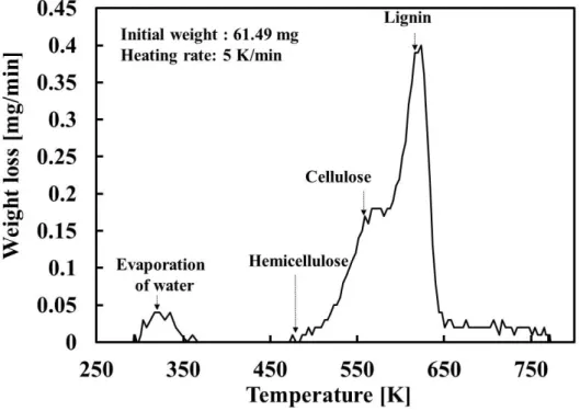
Figure 2-7 shows an example of Thermogravimetric analysis (TGA) curve of sugarcane bagasse. The TGA curve was measured under nitrogen atmosphere with flow rate of 200 ml/min and heating rate of 5 K/min. Weight loss of the sample starts with the evaporation of water (350 K) and followed by decomposition of hemicellulose (470-530 K), cellulose (510-620 K) and lignin (550-770 K). The carbonization via superheated steam and nitrogen gas seems to proceed due to the thermal decomposition as shown in Fig. 2-6.
Fig. 2-7 An example of TGA curve of bagasse.
25
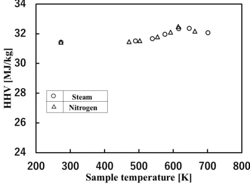
2.3.3 Higher heating value (HHV)
The HHV for both atmospheres of superheated steam and nitrogen gas were calculated by Eq. (3) to evaluate the quality of char as a fuel. Figure 2-8 shows the effect of carbonization temperature on the HHV. Carbon is the element that increases the heating value while oxygen is the element that suppresses the heating value of char.
With the increase in carbonization temperature, the HHV remained almost constant until about 500 K, increased until about 650 K and decreased slightly after that as shown in Fig. 2-7. The decrease in the HHV was due to the decreasing carbon content at this temperature as shown in Table 2-5. As described before, the secondary cracking of the char into gaseous products seems to cause the decrease in carbon content above the temperature around 650 K.
Fig. 2-8 Relationship between higher heating value and sample temperature in superheated steam and nitrogen gas heating practices at 30 min of
carbonization.
26
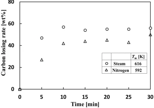
2.3.4 Carbon losing rate
The effect of carbonization time on the carbon losing rate calculated by Eq. (4) is shown in Fig. 2-9. The results indicated that the carbon losing rate for both superheated steam and nitrogen have the same trend, that is, the carbon losing rate increased until 10 min and after that it was almost kept constant. Due to the difference of sample temperature between superheated steam and nitrogen, superheated steam practice had a higher carbon losing rate compared with nitrogen.
Fig. 2-9 Change in carbon losing rate with time.
27
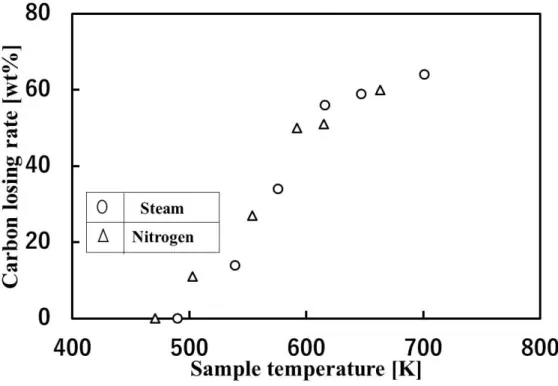
Figure 2-10 shows the effect of carbonization temperature on the carbon losing rate for superheated steam and nitrogen practices at 30 min of carbonization time. Carbon losing rate increased with the increase in carbonization temperature for both methods.
There was no different trend between superheated steam and nitrogen heating practices.
It suggests that the pyrolysis by superheated steam occurs without oxidation and hence the char yield in both cases were almost the same in Fig. 2-5.
Fig. 2-10 Relationship between carbon losing rate and sample temperature at 30 min of carbonization.
28
2.3.5 Calculation model for heat transfer behavior of superheated steam and nitrogen in bagasse pyrolysis
Heat transfer of superheated steam and nitrogen heating practices has been studied in this research. Superheated steam dries the material by convection, radiation and condensation heat transfers compared with hot air or nitrogen gas which only dries through convective heat transfer [20, 24, 28, 29, 38]. Heat transfer properties of superheated steam can be calculated by using a heat balance equation as follows [39]:
hA(Tshs -Tm) + ԑ12σA(Tshs4 – Tm4) + m0(dW/dt)rs = {m0(C0 + WCw)}(dTm/dt) (5) where, h: heat transfer coefficient [W/m2∙K], A: surface area of sample [m2], Tshs :
steam temperature [K], Tm : sample temperature [K], ԑ12 : emissivity of superheated steam and sample [-], σ: Stefan–Boltzmann constant [W/m2∙K4] , m0 : sample weight [kg], rs : latent heat of condensation [J/kg], C0 : specific heat of sample (= 2000 [J/kg∙
K]) [39], W : water content in sample [kg-water/kg-sample] , Cw : specific heat of water [J/kg∙K].
The left side of Eq. (5) is convection, radiation and condensation heat transfers, respectively, and at the right side is the sensible heat of the sample. The following assumptions should be given to obtain the proper calculation.
1) There is no steam condensation during the carbonization because the experimental temperature is sufficiently high.
2) Each heat transfer coefficient of superheated steam and nitrogen heating is constant in the temperature range of this experiment.
According to the above assumption 1) and the initial water content, Wi = 0 [kg-water/kg-sample], in this experimental condition, terms of the water condensation and the heat of evaporation can be neglected in Eq. (5), that is, dW/dt = W =0.
29
The h value in Eq. (5) was changed until the calculated sample temperature matched with the experimental temperature. Using ԑ12 described in 2.3.6, heat balance equation of Eq. (5) was solved by Runge-Kutta Fehlberg method.
2.3.6 Setting of emissivity, ԑ
12Emissivity between superheated steam and the sample were calculated by using the following equation:
1/ԑ12 = 1/ԑ1 + A1/A2{(1/ԑ2)-1} (6) where ԑ1 is biomass sample emissivity [-], ԑ2 is superheated steam emissivity [-], A1 is
surface area of the sample[m2], and A2 is the surface area of superheated steam [m2].
Emissivity of the sample used in this research was 0.90 which is the emissivity value of woody biomass. Effective gas thickness, LG [m], of the superheated steam is required for the calculation of the emissivity, ԑ2, of the superheated steam and can be calculated using the equation below [39].
LG = 4 × (Volume of superheated steam /surface area of superheated steam) × 0.85 (7) Volume and surface area of superheated steam were calculated from the size of the reaction chamber used in this experiment (Fig. 2-1) and the effective gas thickness became 0.17 m. From the superheated steam radiation diagram and LG =0.17 m, the value of superheated steam emissivity, ԑ2, was 0.29 at 491 K, 0.28 at 541 K, 0.27 at 579 K, 0.26 at 617 K, 0.26 at 650 K and 0.24 at 663 K, respectively [40].Finally, the emissivity between superheated steam and the sample was calculated and the result was 0.88 at all temperatures.
30
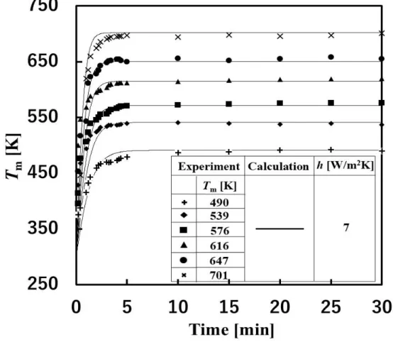
2.3.7 Comparison of sample temperature change between experimental and calculated values
Figure 2-11 shows the temporal change in sample temperature of the experiment and calculation for superheated steam practice. The sample temperature increased rapidly and became constant until 5 min. Most of the results showed a good agreement between the calculated and experimental temperature when h = 7 W/m2∙K was used. The temporal change in sample temperature of the experiment and calculation with no radiation, that is, ԑ12σA(Tshs4 – Tm4) =0 in Eq. (5) is shown in Fig. 2-12. The calculated curve increased more slowly than the experimental one. Thus, the radiation heat transfer by superheated steam played an important role in the pyrolysis of sugarcane bagasse [40].
31
Fig. 2-11 Experimental and calculated sample temperature change with time for superheated steam heating.
32
Fig. 2-12 Experimental and calculated sample temperature change with time for superheated steam heating (calculation of no radiation).
Two kinds of the temporal change in sample temperature of the experiment and calculation for nitrogen gas using electric furnace is shown in Fig. 2-13. Here, the calculation model of nitrogen only consists of convective heat transfer because neither condensation nor radiation occurs during the carbonization with nitrogen gas. The experimental sample temperature was moderately increased and held constant between 10 and 15 min. A good agreement was achieved between the experiment and calculation when the value of h=9 W/m2∙K in Eq. (5) was used.
33
Fig. 2-13 Experimental and calculated sample temperature change with time for nitrogen gas heating.
34
The difference of the h value between superheated steam and nitrogen is estimated to be due to the physical properties and the experimental conditions.
The correlation for heat convection of fluid parallel to flat plate is given by Eq. (8).
[41].
Nu ∝Re1/2 Pr1/3 (8) Nu ≡ hL/λ (9)
Re≡ ρud/μ (10) Pr ≡ Cpμ/λ (11) Here, Nu: Nusselt number [-], Re: Reynolds number [-], Pr: Prandtl number [-], L: plate length [m], λ: thermal conductivity [W/m·K], ρ: fluid density [kg/m3], u: fluid velocity [m/s], d: equivalent cross-sectional area diameter [m], μ: viscosity [Pa·s], Cp: heat capacity at constant pressure [J/K·kg]. Substituting the average physical properties between 490 and 702 K and the experimental conditions into Eq. (8), the following equation is given.
Nusteam/Nunitrogen = (Resteam/Renitrogen)1/2 (Prsteam/Prnitrogen)1/3
= [(0.37/0.57)(0.23/1.48)(0.21/0.05)/(3.1x10-5/3.6x10-5)]1/2x [(2.0x10³/1.1x103)(3.1x10-5/3.6x10-5)/(4.6x10-2/4.4x10-2)]1/3
= 0.80 (12) Here, the suffixes of steam and nitrogen mean superheated steam and nitrogen heating, respectively. Thus,
hsteam/hnitrogen = (λsteam/λnitrogen) (Nusteam/Nunitrogen)
= (4.6x10⁻²/4.4x10-2)(0.80) = 0.84 (13)
35
On the other hand, hsteam/hnitrogen value of this experimental study is obtained from Figs. 10 and 12 as follows.
hsteam/hnitrogen = 7/9 = 0.78 (14) Considering that the average values of the physical properties and the experimental
conditions were used for the calculation of Eq. (12), the experimental heat transfer coefficient was roughly explained by the correlation equation of heat transfer coefficient in Eq. (8).
Next, we compare the heat transfer coefficients of superheated steam and nitrogen at the same experimental conditions, that is, the same u and d values in Eq. (10). Thus,
hsteam/hnitrogen = (λsteam/λnitrogen) (Nusteam/Nunitrogen)
= (λsteam/λnitrogen) (Resteam/Renitrogen)1/2 (Prsteam/Prnitrogen)1/3 =(4.6x10⁻²/4.4x10-2)x[(0.37/0.57)/(3.1x10-5/3.6x10-5)]1/2x
[(2.0x10³/1.1x103)(3.1x10-5/3.6x10-5)/(4.6x10-2/4.4x10-2)]1/3
=1.04 (15) The almost same heat transfer coefficient was obtained for superheated steam and
nitrogen in the above temperature range.
Figure 2-14 shows the predicted sample temperature change of superheated steam and nitrogen gas when the final sample temperatures are 616 and 539 K, and the same h value of 5 W/m2∙K. The temperature of superheated steam approached to the set temperature faster than that of nitrogen gas due to the addition of radiation heat transfer.
In this situation, carbonization of biomass via superheated steam is preferable to heated nitrogen.
36
As large amount of heat is necessary to produce superheated steam compared to the same temperature of nitrogen, it is desirable to make use of the extra energy for superheated steam generation at works such as steelmaking plant etc.
In this study, the dry sugarcane bagasse was used to investigate the carbonization and heat transfer behavior. As the next step, the raw sugarcane bagasse with water content will be used to make clear the effect of water condensation and evaporation on the temperature change during pyrolysis in superheated steam.
Fig. 2-14 Comparison of temporal change in calculated temperature change between superheated steam and nitrogen gas at the same carbonization
temperature.
37
2.4 Conclusions
The carbonization of the sugarcane bagasse and its heat transfer behavior during the pyrolysis in superheated steam and nitrogen atmospheres.
1) The char yield, elemental analysis, higher heat value, and carbon losing rate of superheated steam showed the same tendency as that of nitrogen heating at the treatment temperature between 491 and 702 K.
2) The same carbonization behavior of sugarcane bagasse during the pyrolysis between superheated steam and nitrogen gas suggests no additional oxidation by superheated steam occured.
3) The differences in the char yield, elemental analysis, higher heat value, and carbon losing rate between superheated steam and nitrogen in this experiment were due to the difference in the sample temperature.
4) A good agreement was achieved between the temporal change in sample temperature of the experiment and calculation for superheated steam and nitrogen gas heating practices.
5) The heat transfer of superheated steam was faster than that of nitrogen gas due to additional radiative heating.
38
2.5 References
(1) E. Parparita, M. Brebu, M. A. Uddin, J. Yanik, C. Vasile, “Pyrolysis behaviors of various biomasses,” Polym. Degrad. Stab., 100 (1), 1-9 (2014)
(2) A. Nzihou, “Toward the valorization of waste and biomass,” Waste Biomass Valor., 1 (1), 3-7 (2010)
(3) S. Yaman, “Pyrolysis of biomass to produce fuels and chemical feedstocks,” Energy Convers. Manag., 45, 651-671 (2004)
(4) M. F. Demirbas, M. Balat, “Biomass pyrolysis for liquid fuels and chemicals: A review,”Sci. Ind. Res.66, 797-804 ( 2007)
(5) M. F. Demirbas, “Biomass resources for energy and chemical industry,” Energy, Educ. Sci. Technol., 5, 21-45 (2000)
(6) M. F. Demirbaş, “Biomass resource facilities and biomass conversion processing for fuels and chemicals,” Energy Convers. Manag., 42, 1357-1378 (2001)
(7) M. F. Demirbas, “Bioenergy, Global Warming, and Environmental Impacts,”
Energy Sources, 26, 225-236 (2004)
(8) P. Taylor, M. F. Demirbaş, “Biomass to charcoal, liquid, and gaseous products via carbonization process,” Energy Sources, 23, 579-587 (2001)
(9) I. F. Titiladunayo, A. G. McDonald, O. P. Fapetu, “Effect of temperature on biomass product yield from selected lignocellulosic biomass in a pyrolysis process,” Waste Biomass Valor., 3 (3), 311-318 (2012)
(10) W. Kwaspinski, C. M. P. Byrne, E. Kyyachko, “Biochar from biomass and waste,”
Waste Biomass Valor., 1 (2), 177-189 (2010)
(11) Ministry of Agriculture, Forestry, and Fisheries J, “The Asian biomass handbook support project for building Asian-partnership,”, 338 (2008)
39
(12) M. Sagehashi, N. Miyasaka, H. Shishido, A. Sakoda, “Superheated steam pyrolysis of biomass elemental components and Sugi (Japanese cedar) for fuels and chemicals,” Bioresource Technology, 97, 1272-1283 (2006)
(13) Q. Yan, H. Toghiani, F. Yu, Z. Cai, “Effects of pyrolysis conditions on yield of bio-chars from pine chips,” For Prod, 61, 367-371 (2011)
(14) C. E. Braz, P. M. Crnkovic, “Physical – chemical characterization of biomass samples for application in pyrolysis process,” Chem. Eng. Trans., 37, 523-528 (2014)
(15) M. F. Demirbas, G. Arin, “An overview of biomass pyrolysis,” Energy Sources, 24, 471-482 (2002)
(16) C. Ciubota-Rosie, M. Gavrilescu, M. Macoveanu, “Biomass - an important renewable source of energy in Romania,” Environ. Eng. Manag. J., 7, 559-568 (2008)
(17) A. V. Bridgwater, D. Meier, D. Radlein, “An overview of fast pyrolysis of biomass,” Org. Geochem., 30, 1479-1493 (1999)
(18) M. Pach, R. Zanzi, E. Björnbom, “Torrefied biomass a substitue for wood and charcoal,” 6th Asia-Pacific Internatioonal Symp Combust Energy Util., 6 (2002) (19) A. V. Bridgwater, “Catalysis in thermal biomass conversion,” Appl Catal A, Gen.,
116, 5-47 (1994)
(20) N. Maruyama, Y. Ichihashi, D. Tanaka, T. Shimizu, “Environmental Evaluation of Material Resource Recycle System from High Water Content Waste to Solid Fuel using Superheated Steam,” 5th Int Energy Convers. Eng. Conf. Exhib., 7, 363-369(2007)
40
(21) T. Iwasaki, S. Mizuhashi, S. Watano, T. Akachi, H. Yoshida, “Recovery of Valuables from Wood Waste by Superheated Steam Carbonization,” Asian Pacific Confederation of Chemical Engineers Congress program and abstracts, 3P-06-056, 1-9 (2005)
(22) O. Yamada, “Generation of hydrogen gas by reforming biomass with superheated steam,”Thin Solid Films., 509, 207-211 (2006)
(23) E. K. Bahrin, A. S. Baharuddin, M. F. Ibrahim, M. N. Abdul Razak, A. Sulaiman, S. Abd-Aziz, “Physicochemical property changes and enzymatic hydrolysis enhancement of oil palm empty fruit bunches treated with superheated steam,”
BioResources, 7, 1784-1801 (2012)
(24) T. Amatsubo, Y. Hagura, “Heat transfer characteristics of superheated steam combined with far infrared heating,” Food Sci. Technol. Res., 11, 363-368 (2005) (25) A. Isa, Y. Hagura, “Investigation of carbonization energy for waste biomass in
superheated steam combined with far-infrared heating,” Japan J Food Eng., 12, 39-45 (2011)
(26) W. H. Chen, S. C. Ye, H. K. Sheen, “Hydrothermal carbonization of sugarcane bagasse via wet torrefaction in association with microwave heating,” Bioresour.
Technol., 118, 195-203 (2012)
(27) M. Nan, A. S. Baharuddin, E. K. Bahrin, A. Sulaiman, M. N. Naim, R. Zakaria,
“Enzymatic saccharification of oil palm mesocarp fiber (OPMF) treated with superheated steam,” BioResources, 8, 1320-1331 (2013)
(28) N. Maruyama, D. Tanaka, M. Tamada, T. Shimizu, M. Hirota, “Waste recycling using superheated steam and its environmental evaluation,” 7th International
41
Energy Conversion Engineering Conference, Denver, Colorado, August 2-5 (2009)
(29) N. Maruyama, D. Tanaka, M. Tamada, T. Shimizu, A. K. Gupta, “Experimental investigation to process high water content waste to solid fuel using superheated steam,”The Second International Energy 2030 Conference, 136-137 (2008) (30) J. Zandersons , J. Gravitis, A. Kokorevics, A. Zhurinsh, O. Bikovens, A.
Tardenaka, “Studies of the Brazilian sugarcane bagasse carbonisation process and products properties,”Biomass and Bioenergy, 17, 209–219 (1999)
(31) M. Inyang, B. Gao, P. Pullammanappallil, W. Ding, A. R. Zimmerman, A.R,
“Biochar from anaerobically digested sugarcane bagasse,” Bioresour Technol., 101, 8868-8872 (2010)
(32) C. G. Mothe, I. C. de Miranda, “Characterization of sugarcane and coconut fibers by thermal analysis and FTIR,” J. Therm Anal. Calorim. 97, 661-665 (2009) (33) K. Phichai, P. Pragrobpondee, T. Khumpart, S. Hirunpraditkoon, “Prediction
Heating Values of Lignocellulosics from Biomass Characteristics,” Int. J. Chem.
Mater. Sci. Eng., 7, 1-4 (2013)
(34) T. Assefaaragaw, “Proximate analysis of cane bagasse and synthesizing activated carbon: emphasis on material balance,”J. Environ. Treat. Tech., 4, 102-110 (2016) (35) M. K. Rafiq, R. T. Bachmann, M. T. Rafiq, Z. Shang, S. Joseph, R. L. Long,
“Influence of pyrolysis temperature on physico-chemical properties of corn stover (zea mays l.) biochar and feasibility for carbon capture and energy balance,” PLoS.
One, 11, 1-17 (2016)
42
(36) A. A. Rahman, N. Abdullah, F. Sulaiman, “Temperature effect on the characterization of pyrolysis products from oil palm fronds,”Adv. Energy Eng., 2, 14-21 (2014)
(37) M. U. Hanif, S. C. Capareda, J. Kongkasawan, H. Iqbal, R. O Arazo, M. A. Baig,
“Effects of pyrolysis temperature on product yields and energy recovery from co-feeding of cotton gin trash, cow manure, and microalgae: A simulation study,”
PLoS. One, 11, 1-11 (2016)
(38) T. Hase, M. A. Uddin, Y. Kato, M. Fukui, Y. Kanao, “Chlorine removal mechanism from municipal solid waste using steam with various temperatures,”
Energy Fuels, 28, 6475-6480 (2014)
(39) T. Hase, M. A. Uddin, Y. Kato, M. Fukui, “Drying and organic chlorine thermal decomposition behavior of municipal solid waste using superheated Steam,” J.
Japan Soc. Mater. Cycles Waste Manag., 25, 16-24 (2014) (40) K. Suzuki, “Kanetsusuijouki no tokusei,” Tokyo, NTS (2005)
(41) The Chemical Society of Japan. Handbook of Chemistry. Rev. 2nd ed., Maruzen, Tokyo, (1975)
43
Chapter 3 Dechlorination of polyvinyl chloride under superheated steam
3.1 Introduction
In recent year, the use of plastics materials in daily life have been increased because of their low price and good durability, which resulted in the huge amount of plastic waste released in the world. This plastic waste is considered as an important source of energy due to the presence of the organic compounds which can be served as hydrocarbon raw material or fuel if treated correctly [1-6]. However, the disposal of plastic wastes become a major environmental issue because plastic waste is normally non-biodegradable and contain polyvinyl chloride (PVC) [1, 6-8]. Generally, 7 to 10%
of total plastic waste contains PVC [9-10].
Thermal degradation (pyrolysis, gasification, hydrogenation, etc.) and incineration was the main technology used for PVC recycle [3, 11]. Because of their high chlorine content, PVC is resistant to incineration. Incineration of PVC also emit greenhouse gas such as CO2 and other toxic pollutants [3, 5, 11-16]. However, thermal degradation of PVC generates a lot of HCl and other toxic substances which cause corrosion of the equipment and other environmental problems [9, 13, 15, 17-26]. For the reasons described above, dechlorination of PVC is an essential step before being used in another chemical process for the conversion into energy, fuel, and other useful chemicals [16, 27]. Numerous studies have been conducted on dechlorination of PVC. Pyrolysis is considered the most efficient way for PVC dechlorination [1, 3, 6, 14, 28-30]. It is a thermal process which decomposes organic materials in the absence of air [16, 31-33].
44
During this process, HCl was eliminated and the formation of conjugated double bonds occurs [13]. HCl product can be used for vinyl chloride production [34].
Recently, superheated steam treatment has gained much attention due to simplicity of the dechlorination equipment and low operating temperature [35-36]. Using superheated steam as dechlorination atmosphere, the dechlorination can be faster [37-39]. Moreover, the addition of catalysts such as solid acid catalysts and adsorbents alkali and metal oxide can increase dechlorination rate and lowered reaction temperature [2, 10-11, 17, 31, 40-42]. If the dechlorination can be carried out at low temperature, it can reduce organic volatile, increase solid product yield and save energy. The purpose of this study is to investigate the process conditions for the removal of chlorinated compounds from PVC using catalysts and adsorbents under superheated steam atmosphere.
3.2 Experimental
Commercial PVC powder (Kishida Chemical Co., Ltd.) (99.0% purity) has been used as feedstock in this experiment. The chlorine content of PVC was 55.9%
(analytical data). 5 g of PVC powder was compressed to the pellet using a hydraulic press to make it easy to put it in the sample basket.
Dechlorination experiment was carried out using superheated steam device (Dai-ichi High Frequency Co., Ltd., Hi-Heater 2005S) as shown in Fig. 3-1. The device consists of a boiler, superheated steam generator, and reaction chamber. Steam was produced by the boiler and then the temperature was risen to the setting temperature using a superheated steam generator. Two thermocouples (A, B) were attached to the reaction chamber (A) and sample (B) to measure chamber and sample temperatures.
The flow rate of superheated steam was kept to 10 kg/h. The dechlorination reaction
45
was carried out for 60 min. After the reaction was complete, the sample was cooled down to 343 K and the residue was ground with a blender before further analysis.
The sample after the experiment was treated with hot water and then filtered to obtain inorganic chlorine solution. Organic chlorine content from the remaining sample after filtration was analyzed by Eschka method [43-45]. The chlorine content of both inorganic and organic solution was analyzed using Mercury thiocyanate absorption spectrophotometry method [46].
The yield and dechlorination ratio were defined as Eqs. (1) and (2), respectively.
Yield [%] = (Wf/W0)x100 (1) Dechlorination ratio [%] = {(W0Cl0-WfClf)/(W0Cl0)}x100 (2)
where, Wf and W0 are the masses of the initial and final PVC sample [g], respectively, Cl0 and Clf are the total chlorine contents in the initial and final PVC sample [%]. The total chlorine content means the sum of organic and inorganic chlorine contents in the sample.
For the temperature effect, the reaction was carried out at 473, 498, 523 and 573 K for 60 min. 30, 60, and 90 min of residence times were utilized for 498 K to investigate the effect of residence time on the dechlorination of PVC. In the case of dechlorination using catalysts, β-zeolite and TiO2 were used. NaOH was used as alkali adsorbent and MgO and CoO were used as metal oxide adsorbents in this study. All the reaction with the catalysts and adsorbents were carried out at 473 K for 60 min and PVC weight was fixed to 5 g.
The effect of dechlorination atmosphere was studied under nitrogen gas using electric furnace as shown in Fig. 3-2. The experimental conditions were 473 and 523 K with 60 min of dechlorination time.
46
Fig. 3-1 Schematic diagram of superheated steam.
Fig. 3-2 Schematic diagram of electric furnace.
47
3.3 Results and discussion
3.3.1 Effect of dechlorination temperature and residence time
The effect of the dechlorination temperature on solid product yield and dechlorination ratio are shown in Fig. 3-3. Generally, product yield decreased with the temperature because the reaction rate increased. Product yield decreased to 37.4% at 573 K. The dechlorination ratio of PVC without additive at 473, 298, 523 and 573 K were 12.9, 42.7, 79.8, and 96.5%, respectively. Almost all chlorine was released at 573 K [47]. These results indicated that the temperature is the most important factor that controlled dechlorination process. Remaining of the chlorine compounds in PVC after the experiment without additives is in the state of organic chlorine. The color of PVC also changed from white to brown and became darker at higher temperatures as shown in Fig. 3-4. The color change is influenced by conjugated double bond of polyene [5, 48].
Figure 3-5 shows the effect of residence time on the solid product yield and dechlorination ratio of PVC after the reaction. Solid product yield decreased and become constant after 60 min after 60 min of dechlorination. The same trends were observed in dechlorination rate after 60 min. This indicates that one hour is enough time for the declorination of PVC.
48
Fig. 3-3 Effect of the dechlorination temperature on solid product yield and dechlorination ratio.
Fig. 3-4 Color change of the sample after dechlorination.