Storage at Various Middle High Temperature Range
March, 2018
Than Tun Naing
Graduate School of
Natural Science and Technology (Doctor’s Course)
Okayama University
In recent years, energy demand has increased due to the high-energy consumption in domestic and industrial sectors. People’s living standards have improved due to the de- velopment of science and technology but in addition to the depletion of fossil resources.
Fossil fuels have served and fulfilled all human needs of energy for a long era. These fossil fuels caused significant damage to the environment as it leads to global warming, climate change, acid rain etc. In addition, the prices of fossil fuels have increased and are expected to continue in coming years because of the increase in energy demand.
The effective use of alternative energy such as solar power generation and wind power generation that are environmentally friendly are expected. However, these alternatives are susceptible to weather and supplies are unstable. Thus, a thermal storage system that temporarily store energy is required. On the other hand, some factories discard the waste heat energy into the environment from the exhaust system. It leads to air-pollution, global warming and there are a lot of wasted energy that people cannot use. If these types of wasted heat energy can be stored and used somewhere at the desirable time, it will be very useful for human being life and can decrease the unnecessary environmental impact. For these reasons, thermal storage technology plays a very important role. The purpose of this research is to develop the latent heat storage technology and to effectively utilize unused wasted energy that caused by exhausted heat from factories as a heat source of latent heat storage system that recovers the wasted heat energy in the temperature range of 100∼400◦C.
A number of different approaches have been developed to solve this wasted heat en- ergy problem by using different latent heat storage materials that have different melting temperatures. Many researchers present the solidification and melting of the latent heat
storage materials by using differential scanning calorimetry(DSC). In this dissertation, we constructed a latent heat storage system for research purpose and three different latent heat storage materials were observed with different melting temperature range of the wasted heat energy.
For the melting temperature range of 300∼400◦C, the mixtures of NaCl: KCl: LiCl were used. Firstly, many different wt% of the mixtures were studied to get the required melting temperature by using the electric furnace. After getting the latent heat storage mixture, we tested the corrosiveness of some construction materials and selected the appropriate material to construct the experimental device. There are corrosiveness problems because of high temperature. Corrosiveness test of construction materials with latent heat storage mixture were performed by using some anti-corrosive spray, paint and argon gas. For this mixture, some construction materials could be used for experiment device but they were too expensive. And most of the construction materials could not be used because of corrosiveness problems with the latent heat storage material and high melting temperature. We found some difficulties to construct the experiment devise for this temperature range.
The second part of this dissertation presents the latent heat storage material mixture for the melting temperature range of 200∼300◦C. The mixture of NaOH: LiOH were used for this melting temperature range. Firstly, many different mol% of mixtures were studied to get the required melting temperature by using the electric furnace. After getting the latent heat storage mixture, corrosiveness test were performed with some construction materials in order to select the appropriate material to construct the experimental device. According to the corrosiveness test results, we designed and constructed the experimental device by using the stainless steel SS316L. We must use the argon gas to decrease the corrosiveness problems of the construction materials and latent heat storage material mixtures. This device contains the test-section, heating system, and the cooling system. In this system, indirect heat exchange system was used between latent heat storage material mixture and heat transfer oil. By using this device, the melting and solidification process and behavior of this latent heat storage material mixture were investigated.
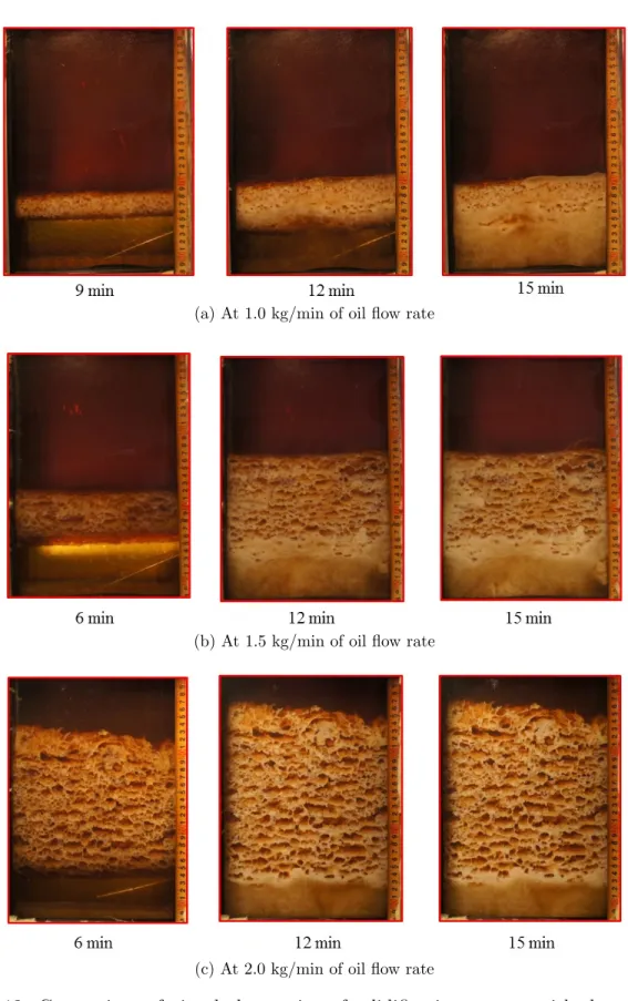
system using middle-temperature waste heat of 100∼200 C from factories. Direct contact melting and solidification behaviors between the heat-transfer fluid and the latent heat stor- age material mixture were observed. The mixture consisted mannitol and erythritol (Cm = 70 mass %, Ce = 30 mass %) as a phase-change material (PCM). The weight of the PCM was 3.0 kg and the flow rates of the oil, foil, were 1.0, 1.5, or 2.0 kg/min. While making the solidification process, the solidification height increases as the flow rate of heat transfer oil increases. There was a flow out problem of PCM from the test-section with the heat transfer oil at high flow rate of oil. We attempted to control the solidified height of the PCM mixture during the solidification process,by installing a perforated partition plate in the PCM region inside of the heat storage vessel. PCM coated oil droplets were broken by the perforated partition plate, preventing the solidified height of the PCM from increasing.
The solidification and melting processes were repeated using metal fiber. It was found that installing the metal fiber were more effective than installing the perforated partition plate to prevent the flow out problem of the PCM. While using the perforated partition plate and metal fiber, the amount of heat release were slightly lessened than without of that. To increase the amount of heat release during the solidification process, the effects of metal fiber diameter, the proportion of fibers, and the position of the fibers within the PCM region were also investigated. As a result, the most effective conditions employed metal fibers with a diameter of 0.2 mm. The numerical calculation was performed to predict the temperature of the mixture and compared it with the experimental results . As a results, the temperature trends of the numerical calculation were nearly the same with the experimental results.
The success of this research work in this thesis became possible due to a lot of help from many people during my Ph.D. study at Okayama University. Firstly, I would like to express my deepest gratitude to my advisor, Professor Akihiko Horibe, for his valuable guidance, encouragement, patience, motivation, and support in completing the research work in this thesis.
I wish to express my thanks to Professor Naoto Haruki and Assistant Professor Yutaka Yamada for their suggestions and comments throughout my Ph.D. research. Their kind guidance, encouragement, and patience have been a great support throughout my research.
I would like to thank my thesis committee members, Professor Eiji Tomita and Pro- fessor Shinichiro Yanase, for their encouragement, insightful comments and reviewing this dissertation. I feel proud and honored that you have accepted to be on my committee.
In this study, as co-researcher with Mr. Yoshitaka Takase, and Mr. Nobumasa Suzuki who performed the work with the author, Mr. Mazakazu Shinoda and Mr. Shiro Sugitani who cooperated in all processes from the production of the experimental apparatus to the implementation of the experiment and the data arrangement. I wish to express my gratitude here for their efforts to make this research fruitful.
I wish to express my thanks to Mr. Tatsuya Imai. It is one of the most fun memories when we were talking at the Heat Transfer Laboratory. I will remember your word that I am ever ready for Naing San for preparing the experimental device. I deeply thanks for helping not only in the workshop but also for daily life in Japan.
I also would like to thank all previous and current student members of Heat Transfer Laboratory, who have been very helpful not only in the laboratory but also in personal mat-
ters. I also would like to thank the staff from Centre of Global Partnerships and Education for their kind help during my stay at Okayama University.
The writing of this dissertation became possible due to the financial support by Japan International Cooperation Agency (JICA), Heat Transfer Laboratory and Okayama Univer- sity.
Finally, I would like to offer my special thanks to my family, my wife, who always give encouragement, support, and good advice.
Contents
Abstract i
Acknowledgements v
List of Figures xii
List of Tables xix
1 Introduction 1
1.1 Introduction . . . 1
1.2 Background and Motivation . . . 2
1.3 Purpose of this study . . . 5
1.4 Structure of this thesis . . . 6
2 Thermal Energy Storage Technology 8 2.1 Thermal energy storage system . . . 9
2.2 The utilization of the heat storage technology . . . 10
2.3 Heat Storage Method . . . 11
2.4 Phase Change Material . . . 13
2.4.1 Required properties for phase change material . . . 13
2.4.2 Classification of PCM . . . 16
2.4.3 Previous researches on latent heat storage materials . . . 18 3 Heat Storage Material Mixture at Temperature Range 300∼400◦C 24
3.2 Corrosion Test without Using Any Paint and Spray . . . 29
3.3 Corrosion Test with Using Some Spray and Paint . . . 35
3.4 Corrosion Test by Using Argon Gas . . . 40
3.5 Summary . . . 46
4 Heat Storage Material Mixture at Temperature Range 200∼300◦C 49 4.1 Selection of Heat Storage Material . . . 51
4.2 Melting Point Measurement . . . 52
4.2.1 LiOH-LiCl Mixture . . . 54
4.2.2 LiOH-KOH Mixture . . . 55
4.2.3 NaOH-LiOH Mixture . . . 56
4.2.4 Corrosion Test with NaOH: LiOH Mixture . . . 57
4.3 Design Consideration of Experimental Apparatus . . . 63
4.4 Experimental Apparatus and Method . . . 64
4.4.1 Test Section and Heating System . . . 64
4.4.2 Test Section and Cooling System . . . 67
4.5 Experimental Result and Consideration . . . 69
4.5.1 Melting process . . . 69
4.5.2 Solidification process . . . 71
4.5.3 Summary . . . 74
5 Heat Storage Material Mixture at Temperature Range 100∼200◦C 76 5.1 Selection of Heat Storage Material . . . 76
5.2 Characteristics of Erythritol and Mannitol . . . 80
5.3 Characteristics of Mixed Latent Heat Storage Material . . . 81
5.4 Experimental Apparatus . . . 83
5.5 Experimental Method . . . 86
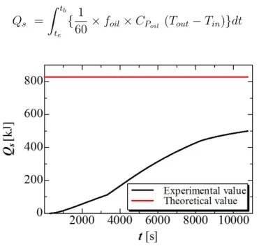
5.6 Method of Arranging Experimental Data . . . 87
5.7 Solidification Behaviors of 70mass% Mixture . . . 89
5.8 Melting Behaviors of 70 mass% Mixture . . . 95
5.9 Methods of the Reduction of the Solidification Height of Mixture . . . 102
5.9.1 Using the Perforated Partition Plate . . . 102
5.9.2 Using the Metal Fiber . . . 107
5.9.2.1 Using the Metal Fiber diameter 0.4 mm . . . 107
5.9.2.2 Effect of changing the proportion of metal fiber . . . 118
5.9.2.3 Effect of changing metal fiber diameter . . . 125
5.9.2.4 Effect of changing the position of metal fibers . . . 129
5.9.3 Using the Aluminum Perforated plate . . . 137
5.9.4 Using Mesh . . . 139
5.9.5 Calculation for PCM temperature . . . 141
5.10 Summary. . . 145
6 Conclusion and Future Work 149 6.1 Conclusion . . . 149
6.2 Future Work . . . 151
List of Publications 154
Bibliography 157
Appendix A 171
Appendix B 178
List of Figures
2.1 Classification of PCM [35]. . . 19
3.1 The proposed experimental device. . . 25
3.2 PCM and their melting temperature. . . 26
3.3 The experimental apparatus for melting point measurement of new PCM and making corrosion test. . . 27
3.4 Melting process of different wt% of NaCl, KCl, and LiCl. . . 28
3.5 PCM conditions of different mixtures at 450◦C. . . 28
3.6 The plate and crucible setting for corrosion test. . . 30
3.7 Plates condition of SS304, SS316, SS316L. . . 30
3.8 PCM conditions with and without steel plates. . . 31
3.9 Condition of copper, brass, carbon steel and SS310 plates before and after the corrosion test(a)before the test, (b) after the test before cleaning and, (c) after cleaning. . . 32
3.10 PCM conditions with test of copper, brass, carbon steel and SS310 plates. . 32
3.11 Condition of aluminum, titanium, nickel and molybdenum plates (a)before the test, (b) after the test before cleaning and, (c) after cleaning. . . 33
3.12 PCM conditions with test of aluminum, titanium, nickel, and molybdenum. . 33
3.13 Temperature histories of PCM with different material plates. . . 35
3.14 Plates condition of SS304, SS316 and SS316L plates with spray Rust Oleum. 36 3.15 PCM condition with test of SS304, SS316, and SS316L with spray Rust Oleum. 36 3.16 Plate conditions of SS304 with Cerakoto Alumina spray. . . 37
3.18 PCM condition with test of SS304, SS316, and SS316L with Cerakoto paint. 38 3.19 Plates condition of SS304, SS316 and SS316L plates with Kure Heat and
corrosion resistant spray. . . 39
3.20 PCM condition with test of SS304, SS316, and SS316L with Kure Heat and corrosion resistant spray. . . 40
3.21 Experimental device for corrosion test with argon gas. . . 40
3.22 Gas pipe setting. . . 41
3.23 Plates conditions after corrosion test with argon gas. . . 42
3.24 PCM conditions after test with argon. . . 42
3.25 Temperature histories of melting process with argon gas. . . 43
3.26 Vacuum furnace. . . 43
3.27 Plates condition with NaCl0%. . . 44
3.28 Plates condition with NaCl23%. . . 45
3.29 Plates condition with NaCl0% without gas. . . 46
3.30 SS304 Plates condition with NaCl0%. . . 46
4.1 Pictures of heat storage materials. . . 52
4.2 The experimental apparatus for melting point measurement. . . 53
4.3 Temperature history of LiOH: LiCl (60.5:39.5)mol%. . . 54
4.4 Temperature history of LiOH: LiCl (40:60) mol%. . . 55
4.5 Temperature history of LiOH: KOH (29:71) mol%. . . 55
4.6 Temperature history of NaOH: LiOH (70:30) mol%. . . 56
4.7 Temperature history of NaOH: LiOH (60:40) mol%. . . 56
4.8 Temperature history of NaOH: LiOH (50:50) mol%. . . 57
4.9 Plate and setting for corrosion test. . . 58
4.10 Plates condition of SS304, SS316, and SS3161. . . 59
4.11 The PCM condition of NaOH: LiOH after corrosion test. . . 59
4.12 Plates condition with NaOH: LiOH with some spray. . . 60
4.13 Nickel and copper plates condition with NaOH: LiOH. . . 62
4.14 Stainless steel and NaOH: LiOH with argon gas. . . 63
4.15 Test section with heating system. . . 66
4.16 Detail of test section. . . 67
4.17 Test section with cooling system. . . 68
4.18 Detail of cooling section. . . 69
4.19 Temperature histories during melting process. . . 70
4.20 Visualization of PCM melting during the melting process. . . 70
4.21 The amount of heat storage by watt meter. . . 71
4.22 Total amount of heat storage. . . 71
4.23 Temperature histories during the solidification process. . . 72
4.24 Visualization of PCM during the solidification process. . . 73
4.25 The total amount of heat release during the solidification. . . 73
5.1 Annual discarded waste heat by various industrial sectors in Japan. [80]. . . 77
5.2 Various heat storage material at the temperature range of 100∼250◦C[81],[82]. 77 5.3 Erythritol and Mannitol material. . . 80
5.4 DSC measurement results of each mixing ratio of mannitol and erythritol [81]. 82 5.5 Schematic diagram of the experimental apparatus. . . 83
5.6 Details of the heat storage vessel. . . 84
5.7 Nozzle plate photo and its dimension. . . 84
5.8 The arrangement of thermocouples. . . 85
5.9 Temperature histories of solidification at 1.0 kg/min flow rate. . . 90
5.10 Visual observation of solidification process at the flow rate of 1.0 kg/min. . . 91
5.11 Temperature histories with three different oil flow rates. . . 92
5.12 Comparison of visual observation of solidification process with three different oil flow rates. . . 94
5.13 The amount of heat released during the solidification process with three dif- ferent oil flow rates. . . 95
5.15 Temperature histories of melting process at 1.0 kg/min of oil flow rate. . . . 97 5.16 Visual observation of melting process at 1.0 kg/min oil flow rate. . . 98 5.17 Temperature histories of melting process at the three different oil flow rates. 99 5.18 Comparison of visual observation of melting process with three different of oil
flow rate. . . 100 5.19 The amount of heat stored in the melting process with three different types
of oil flow rates. . . 101 5.20 The rate of heat released at the three different of oil flow rates. . . 101 5.21 Details of perforated partition plate. . . 103 5.22 Temperature histories of PCM with perforated partition plate at the oil flow
rate of 1.0 kg/min. . . 103 5.23 Solidification behaviors of PCM with and without the perforated partition
plate at the oil flow rate of 1.0 kg/min. . . 104 5.24 Comparison of solidification behaviors with and without perforated partition
plate at three different types of oil flow rates. . . 105 5.25 Comparison of the amount of heat released with and without perforated par-
tition plate at the three types of oil flow rates. . . 106 5.26 Comparison of the speed of heat released with and without perforated parti-
tion plate. . . 107 5.27 Melting behaviors of PCM with the perforated partition plate at the three
types of oil flow rates. . . 108 5.28 Comparison of the amount of heat stored with and without perforated parti-
tion plate at the three types of oil flow rates. . . 109 5.29 Comparison of the rate of heat stored with and without perforated partition
plate at the three types of oil flow rates. . . 110 5.30 Aluminum metal fiber. . . 110 5.31 Metal fiber position. . . 111
5.32 Temperature histories of PCM with metal fiber at the oil flow rate of 1.0 kg/min.111 5.33 Solidification behaviors of PCM with and without inserting of the metal fiber
at the oil flow rate of 1.0 kg/min. . . 112 5.34 Comparison of solidification behaviors with and without inserting of metal
fiber into three different types of oil flow rates. . . 113 5.35 Comparison of the amount of heat released with and without inserting of
metal fiber at the three types of oil flow rates. . . 114 5.36 Comparison of the speed of heat released with and without inserting of metal
fiber at the three types of oil flow rates. . . 115 5.37 Melting behaviors of PCM with the metal fiber at the three types of oil flow
rates. . . 116 5.38 Comparison of the amount of heat stored with and without inserting of the
metal fiber at the three types of oil flow rates. . . 117 5.39 Comparison of the rate of heat stored with and without inserting of the metal
fiber at the three types of oil flow rates. . . 118 5.40 Comparison of solidification behaviors with the metal fiber of φ = 1.5% and
φ = 0.5%. . . 119 5.41 Comparison of solidification behaviors with the metal fiber of φ = 1.5% and
φ = 0.5% at three different flow rates of oil. . . 120 5.42 Comparison of the amount of heat released with the metal fiber of φ= 1.5%
and φ = 0.5%. . . 121 5.43 The rate of heat released with the metal fiber ofφ = 1.5% andφ = 0.5%. . . 122 5.44 Melting behaviors of PCM with the metal fiber φ = 0.5% at the three types
of oil flow rates. . . 123 5.45 Comparison of the amount of heat stored with the metal fiber φ = 0.5% at
the three types of oil flow rates. . . 124 5.46 Comparison of the rate of heat stored with the metal fiber φ = 1.5% and
φ = 0.5%. . . 125
d = 0.2 mm at the oil flow rate of 1.0 kg/min. . . 126 5.48 Comparison of solidification behaviors with the metal fiber ofd= 0.4 mm and
d = 0.2 mm at three different flow rates of oil. . . 127 5.49 Comparison of the amount of heat released with the metal fiber of d = 0.4
mm and d = 0.2 mm. . . 128 5.50 The rate of heat released with the metal fiber ofd = 0.4 mm and d = 0.2 mm. 129 5.51 Melting behaviors of PCM with the metal fiberd= 0.2 mm at the three types
of oil flow rates. . . 130 5.52 Comparison of the amount of heat stored with the metal fiber d= 0.2 mm at
the three types of oil flow rates. . . 131 5.53 Comparison of the rate of heat stored with the metal fiberd = 0.4 mm andd
= 0.2 mm. . . 132 5.54 The different positions of metal fiber at the PCM region. . . 132 5.55 Comparison of solidification behaviors with the metal fiber of different position
at the oil flow rate of 1.0 kg/min. . . 133 5.56 Comparison of solidification behaviors with the metal fiber of different position
at different type of oil flow rates. . . 134 5.57 Comparison of the amount of heat released with the metal fiber of different
position. . . 135 5.58 Comparison of the rate of heat released with the metal fiber of different position.136 5.59 Solidification behavior of PCM for (a) fibers filling entire test region and (b)
fibers only present in the top third of the test region. . . 136 5.60 Melting behaviors of PCM with the metal fiber at one-third of PCM region
at the three types of oil flow rates. . . 137 5.61 Comparison of the amount of heat stored with the metal fiber at different
positions at the three types of oil flow rates. . . 138
5.62 Comparison of the rate of heat stored with the metal fiber at the different
positions. . . 139
5.63 Aluminum Perforated plate. . . 139
5.64 Solidification process with the perforated plate. . . 140
5.65 The rate of heat released with the perforated plate. . . 140
5.66 Two types of mesh. . . 141
5.67 Visualization of solidification process with mesh. . . 141
5.68 Schematic of the test-section. . . 142
5.69 Calculation steps for the temperature histories of PCM. . . 143
5.70 Comparison of results for 1.0 kg/min oil flow rate. . . 145
5.71 Comparison of results for 1.5 kg/min oil flow rate. . . 145
5.72 Comparison of results for 2.0 kg/min oil flow rate. . . 145
4.1 Heat storage materials in the temperature range of 200∼300◦C [76], [79]. . . 51
4.2 LiOH: LiCl mixtures and its melting temperature. . . 54
4.3 NaOH: LiOH mixtures and its melting temperature. . . 57
5.1 Properties of Erythritol and Mannitol [93][94]. . . 81
5.2 DSC measurement values and reference values [81], [93],[94]. . . 82
5.3 The properties of heat transfer fluid oil (silicone) [95]. . . 85
5.4 The specific heat of mixture at different temperature range [96]. . . 143
Cm : mannitol mass % Ce : erythritol mass%
Q: the amount of heat (kJ) f : flow rate of oil (kg/min) Cp : specific heat (kJ/kgK) t : time (min)
T : temperature (◦C)
∆T : temperature difference (◦C) L: latent heat (kJ/kg)
m : mass (kg)
φ : the ratio of heat with experiment and theoretical P : the rate of heat(kJ/s)
h: enthalpy(kJ/kg)
Subscripts M : melting process S : solidification process oil: heat transfer fluid oil P CM : phase change material l : liquid
s : solid
e: end of process
b : beginning of process m : melting
f : finishing time th : theoretical value ts: test section in : inlet
out: outlet M ix: mixture a : ambient
Introduction
1.1 Introduction
In recent years, energy demand has increased due to the high-energy consumption in domestic and industrial sectors. People’s living standards have improved due to the devel- opment of science and technology but in addition to the depletion of fossil resources. Fossil fuels have served and fulfilled all human needs of energy for a long era. These fossil fuels caused significant damage to the environment that leads to global warming, climate change, acid rain etc. In addition, the value of fossil fuels have increased and are expected to continue through the coming years because of the increase in energy demand.
The effective use of alternative energy such as solar power generation and wind power generation that are environmentally friendly are expected. However, these alternatives are susceptible to weather and supply are unstable, thus temporarily store energy and require a storage system to supply it when needed. If these types of waste heat energy can be stored somewhere and used at the desirable time, it will be very useful for human life and be able to decrease the unnecessary environmental impact. For these reasons, thermal storage technology plays a very important role. To store these wasted heat energy, it can use sensible heat storage, latent heat storage, and chemical heat storage. Researchers on thermal storage systems have been actively conducted, including latent heat storage systems that utilize sensible heat storage that stores heat due to temperature changes of substances, latent heat
Chapter 1. Introduction
generated when a substance undergoes a phase change, chemical thermal storage utilizing chemical reaction and so on. Sensible heat storage is stable and safe, but the thermal storage density is small, chemical storage can store a lot of heat, but reactions at high temperature and high pressure are required, and stability lacks. Therefore, attentions are paid to latent heat storage from the viewpoint of stability and heat storage capacity, and research has been actively carried out.
1.2 Background and Motivation
Thermal energy storage plays an important role for effective use of thermal energy and has applications in diverse areas, such as building heating or cooling systems, solar energy collectors, power and industrial waste heat recovery [1]. The term latent heat storage applies to the storage of heat as the latent heat of fusion in suitable substances that undergo melting or freezing at desired temperature level [2]. The wide range of Phase Change Material (PCM) applications in the construction, electronic, biomedical, textile and automotive industries are presented, and future research directions are indicated. In recent years, the integration of PCMs in thermal storage systems has been a topic of interest in research and development within the heat transfer and renewable energy communities [3]. Solar energy is available during the day only, and its application requires efficient thermal energy storage so that the excess heat collected during sunshine hours may be stored for later use during the night [4]. Major examples of the applications of PCMs include thermal storage of solar energy.
Performance of PCM for solar thermal energy storage was conducted using a commercially available flat-plate solar thermal collector [5] [6]. In order to increase the efficiency of the solar air collector and to improve their thermal efficiency in terms of operating time, hot outlet air temperature and starting operation time, the performance of a compact phase change material solar air heater collector based on latent heat storage energy was investigated [7].
Advanced-structure heat sinks with multi-layer PCMs and hybrid passive heat sinks com- bined with active cooling are also introduced. The PCM-based thermal management system is powerful in ensuring electronic devices, Li-ion batteries and photovoltaic cells working
safely and efficiently [8]. The rapid commercialization of PCMs for heating, ventilation, and air-conditioning(HVAC) applications, has paved way for effective utilization of ambient thermal fluctuations temperature regulation in residential and commercial buildings [9]. The application of PCM in heating and domestic hot water systems can reduce greenhouse gas emission and electrical power consumption [10]. The experimental studies related to PCMs usage in hot water tank and central thermal storage were performed [11], [12]. With the rapid development of construction industry, more and more lightweight building materials are applied in high-rise buildings. PCMs with their high heat storage capacity have been considered for the building thermal storage [13]. The review focuses on PCM technologies developed to serve the building industry. Various PCM technologies tailored for building ap- plications are studied with respect to technological potential to improve indoor environment, increase thermal inertia and decrease energy use for building operation [14].
An optimal design for a PCM underfloor heating system is proposed to reduce energy consumption in apartment buildings and thermal storage performance of the proposed system is evaluated experimentally [15] Latent heat thermal energy storage (LHTES) are becoming more and more attractive for space heating and cooling of buildings. The application of LHTES in buildings has the following advantages: the ability to narrow the gap between the peak and off-peak loads of electricity demand; the ability to save operative fees by shifting the electrical consumption from peak periods to off-peak [16]. Many considerations are discussed in this paper including physical considerations about building envelop and PCM [17]. Thermal energy storage used for air conditioning systems and the application of PCMs in different parts of the air conditioning network, air distribution network, chilled water network, microencapsulated slurries, thermal power and heat rejection of the absorption cooling. It is expected that the design of latent heat thermal energy storage will reduce the cost and volume of the air conditioning systems and networks [18].
Heat storage materials which can store wasted heat at medium-temperature around 200∼400◦C were discussed. Wasted heats around 200∼400◦C are emitted as exhaust gases from an internal combustion engine, co-generation, high-temperature process and solar sys-
Chapter 1. Introduction
tems. Amount of exhaust gas emission are quite large and needed to utilize well for energy efficiency improvement [19]. A phase change material acting as thermal mass is attached to one side of the thermoelectric generators while the other side is placed on the aircraft structure. The application area under investigation for this paper is the pylon aft fairing, located near the engine of an aircraft, with temperatures reaching on the inside up to 350◦C [20] . The work on thermal energy storage materials, development of PCMs classification, working principle of PCMs and working of PCMs in clothing were studied. The review also summarizes the evaluation of textiles containing PCM and different applications Paraffinic hydrocarbon are widely used in textiles than other PCM due to its outstanding properties such as noncorrosiveness, chemical, and thermal stability and low under cooling [21]. The use of latent heat thermal energy storage for thermally buffering vehicle systems is reviewed.
Vehicle systems with transient thermal profiles are classified according to operating tem- peratures in the range of 0∼800◦C. A comprehensive overview of phase change materials covering the relevant operating range are given, including selection criteria and a detailed list of over 700 candidate materials from a number of material classes [22]. Thermal energy storage forms a key component of a power plant for improvement of its dispatch ability.
Though there have been many reviews of storage media, there are not many that focus on storage system design along with its integration into the power plant [23].
The continuous increase in the level of greenhouse emissions gas and the climb in fuel prices are the main driving forces behind efforts more effectively utilize various sources of renewable energy. One of the options is to develop energy storage devices, which are as important as developing new sources of energy. The storage of energy in suitable forms, which can conventionally be converted into the required form, is a present-day challenge to the technologists [24]. With a global concern about energy and carbon dioxide emissions, renewable energies has attracted extensive attention. One of the crucial aspects is waste heat recovery and thermal energy storage. Phase change materials have unique merits in latent heat thermal energy storage, due to its capability of providing a high-energy density storage by solidifying/melting at a constant temperature [25].
Motivated as shown above reasons, thermal energy storage technology is essential for energy required problem and to protect the environment impact. New heat storage materials are required as much as we can at various temperature zone to store wasted heat energy. In this research, three different heat storage materials are investigated for different temperature range and construct the latent heat storage system for research purpose.
1.3 Purpose of this study
As shown in the previous section, the latent heat storage technology is widely used large ranges of utilization. One of the problems of the latent heat storage material is that the melting temperature of this material is fixed and cannot be changed. Even though there is a waste heat source at a certain temperature, there is a possibility that the heat source may be wasted if there is no heat storage material usable at this temperature. In order to solve this problem, many types of research should be made to get the new heat storage materials for various temperature. The purpose of this research is to develop the latent heat storage technology and to effectively utilize unused wasted energy that received by exhaust heat from factories as a heat source of latent heat storage system. Another hand, this latent heat storage system can be used to protect the global warming to minimize the different electricity between day and night, and to minimize the depletion of fossil fuel.
To recover the wasted heat energy in the temperature range (100∼400◦C) discarded from the factories, our research purpose is to determine the new heat storage material mixtures at the temperatures of 150◦C, 250◦C, and 350◦C, and to construct the latent heat storage system. And then study the solidification and melting behaviors, the temperature histories during the heat stored and released process, and the amount of heat required for melting and solidification of each material mixture according to the temperature range.
Chapter 1. Introduction
1.4 Structure of this thesis
This paper consists of all six chapters. The chapters contained in this dissertation can be briefly summarized as follows:
Chapter 1describes introduction and the background information that leads to conduct the research in this thesis.
Chapter 2 presents the thermal energy storage system and required properties and classification of energy storage materials.
Chapter 3describes the selection of heat storage material mixture that melts about the melting temperature of 300∼400◦C. Corrosiveness test of construction material with this heat storage material mixture were performed. And also used anti-corrosiveness sprays and argon gas to determine the corrosiveness of construction materials.
Chapter 4 contains the construction of latent heat storage system of the mixture that melts at the melting temperature of 200∼300◦C. In addition, the melting and solidification behaviors of this mixture was described.
Chapter 5 includes the melting and solidification behaviors of heat storage material mixture that has the melting temperature of 100∼200◦C. While using a mixture of erythritol and mannitol, there is a problem of flow out from the system at the high flow rate of heat transfer fluid oil. The methods are investigated to protect the flow out problem of heat storage material mixture. The numerical calculation is performed to predict the temperature of heat storage mixture and compared to experimental results.
Finally, Chapter 6summarizes the results described in each chapter and concludes this dissertation and future work.
Chapter 2
Thermal Energy Storage Technology
In order to efficiently utilize thermal energy or to increase the efficiency of heat-utilizing equipment, it is necessary to supply the required amount of thermal energy at the desirable time. The thermal storage system is used between thermal energy supply and demand.
By effectively storing and supplying unused energy such as waste heat from factories, it is considered to be an environmentally friendly system that can convert these energy into usable energy at the desire place and time [26]-[27].
Solar energy has a disadvantage that the amount of energy that can be utilized depend- ing on the climate changes greatly. To effectively utilize natural energy like solar energy, therefore, it is necessary to store thermal energy intermittently and store it appropriately.
It is considered that the thermal storage tank installed in the solar water heater used in the private sector has a big influence on the efficiency of the whole system. In addition, in order to effectively use waste heat, the heat storage system is also considered to be very important. To efficiently use the late-night electric power from the power demand difference between the day and night, the heat storage system is a very efficient method. Latent heat thermal energy storage (TES) using phase change materials (PCM) is an effective way of storing thermal energy because of its high energy storage density and the nearly isothermal melting and solidification processes at the phase change transition temperature of the PCM [28].
Generally, in the thermal energy utilization system, the operating temperature is deter-
mined according to the waste heat temperature. The heat storage technology in the thermal storage system is an important technology to make the whole energy utilization system effi- ciently operate. In contrast, the thermal storage system requires the initial investment cost as disadvantage, but unused waste energy can be used as energy supply and reduction effect of greenhouse gas can be directly obtained.
2.1 Thermal energy storage system
The most common way to classify the thermal heat storage method is to distinguish it from sensible heat storage, latent heat storage, and chemical storage according to the stored thermal energy form. The thermal storage system can be used at low temperature (100◦C or less), medium temperature (150∼250◦C), and high temperature (250◦C or higher), and can be distinguished in short-term and long-term thermal storage according to the duration of thermal storage.
The sensible heat storage is a system that uses heat capacity of a substance to store heat energy due to the temperature difference. The experimental investigation studies the performance of a small size sensible heat energy storage unit made of gypsum rocks[29].
Since the principle of thermal storage is simple, there are few technical problems and it is stable such as water, gravel, brick etc. There is an advantage that there are a lot of heat storage materials. However, since the heat storage capacity per unit volume, per unit mass, is small, in addition to the necessity of selecting a huge heat storage device and a heat capacity material with large heat capacity, the heat storage is performed at a temperature higher than the use temperature, which leads to larger heat loss. There are drawbacks. Also, since the efficiency largely changes due to the temperature change of the heat storage facility and the system, it is necessary to have a device for regulating the temperature during heat storage and heat release and a high-performance heat insulating facility.
The latent heat storage utilizes latent heat generated when a substance undergoes a phase change or transition, has a larger heat storage capacity per unit volume, unit mass as compared with sensible heat storage. In the phase change process, since there is no
Chapter 2. Thermal Energy Storage Technology
temperature change, when using the latent heat storage material, the storage capacity per unit volume is large and the volume and weight of the heat storage tank can be greatly reduced compared with the sensible heat storage device. In addition, since heat storage and heat released are performed in the required temperature range, it is expected to be useful in scenes requiring a constant temperature heat source. Latent heat storage method that stores heat energy by using latent heat absorbed or released when changing the phase of the material is a very effective heat storage method.
The chemical storage is a system that utilizes a reversible chemical reaction, temporarily stores thermal energy as chemical energy, and causes a reverse reaction when necessary to convert it to thermal energy [30][31].There are thermochemical reactions, photochemical reactions, adsorption reactions, electrochemical reactions, etc. As chemical reactions, and heat can be stored at a higher density than latent heat storage. In addition to being able to preserve heat for a long period even at room temperature, it also has the feature that it can correspond to a wide temperature range by selecting the reaction condition and can also carry out heat transfer. However, there are many heterogeneous reaction systems in chemical heat storage, and chemical thermal storage materials are expensive. In addition, the reactions require high temperature and high pressure at the time of regeneration. Thus, in order to use it, it is necessary to accurately grasp thermo-physical properties and reactions and to produce highly reliable devices.
2.2 The utilization of the heat storage technology
The utilization of the heat storage technology is in the following systems [32]:
1. PCMs have been widely used in latent heat thermal storage systems for heat pumps, solar engineering, and spacecraft thermal control application.
2. Medical applications: Transportation of blood, operating tables, hot-cold therapies, treatment of asphyxia.
3. PCM applications such as in solar cooking, solar power plants, thermal energy storage.
4. PCMs are also used in textiles.
5. In the case of a power failure to conventional cooling systems, PCMs minimize use of diesel generators, and this can translate into enormous savings across thousands of telecom sites in tropics.
6. Thermal storage of solar energy.
7. Passive storage in bioclimatic building/architecture (HDPE paraffin).
8. Cooling: use of off-peak rates and reduction of installed power, ice bank.
9. Heating and sanitary hot water: using off-peak rate and adapting unloading curves.
10. Safety: temperature maintenance in rooms with computers or electrical appliances.
11. Thermal protection of food: transport, hotel trade, ice-cream, Food agroindustry, wine, milk products (absorbing peaks in demand), greenhouses.
12. Thermal protection of electronic devices (integrated in the appliance) and medical applications: transport of blood, operating tables, hot-cold therapies.
13. Cooling of engines (electric and combustion).
14. Thermal comfort in vehicles.
15. Softening of exothermic temperature peaks in chemical reactions.
16. Spacecraft thermal systems.
17. Solar power plants.
2.3 Heat Storage Method
A heat exchanger is a device used to transfer heat between a solid object and a fluid, or between two or more fluids. Heat exchange method of heat storage system is roughly classified into two. One is an indirect contact latent heat storage technology where heat
Chapter 2. Thermal Energy Storage Technology
storage material filled in heat storage tank exchanges heat with heat transfer medium via heat transfer walls such as shell and tube. Other is direct contact latent heat storage technology that performs heat exchange by making direct contact of heat storage material and heat transfer medium.
(1) Indirect Contact Heat Storage
The fluids may be separated by a solid wall to prevent mixing or they may be indirect contact. The indirect contact has a structure in which a heat exchanger is enclosed in a heat storage tank, and the heat storage material and the heat transfer medium are connected via a heat transfer wall or tube that performs indirect heat exchange. They are widely used in space heating, refrigeration, air conditioning, power stations, chemical plants, petrochemical plants, petroleum refineries, natural-gas processing, and sewage treatment. The heat transfer tube is required to have excellent heat transfer characteristics and not to corrode the heat storage material and the heat transfer medium. Furthermore, since the heat storage material and the heat transfer medium do not come into contact with each other, it is safe to use even substances that react with each other, and the reliability is high because the heat storage material does not flow out. As a disadvantage, since heat exchange is performed via a heat transfer tube, the heat exchange rate is low, and it takes time to store heat and release heat.
(2) Direct contact heat storage
Direct contact heat exchangers involve heat transfer between hot and cold streams of two phases in the absence of a separating wall. In the direct contact, heat transfer medium flows directly into the heat storage tank and performs heat exchange directly with the heat storage material and heat transfer medium. In order to adopt this method, it is necessary that the chemical reaction of both heat storage material and heat transfer oil do not occur, the density of the heat storage material must be higher than the heat transfer oil in order to prevent outflow of the heat storage material. An advantage is that since there is no conduit which becomes thermal resistance compared with an indirect contact, it has high heat exchange rate and can store heat at high density. Construction is very simple and does not hesitate the corrosiveness problem of tube and wall. The lightweight of the direct-contact heat exchanger
enables its use as not only a stationary system but also a heat transport system [33][34]. On the other hand, as a disadvantage, there are a possibilities that the heat storage material flows out outside of the heat storage tank together with the heat transfer medium, the pressure inside the tank fluctuates, and the heat storage material tends to deteriorate easily.
2.4 Phase Change Material
Phase Change Material (PCM) is a substance with a high heat of fusion which, melts and solidifies at a certain temperature, and is capable of storing or releasing large amounts of energy. Phase change materials are latent heat storage substance, in which energy is stored and released in the process of changing the state i.e. either by solid to liquid or liquid to solid. While storing heat in the storage material, the material begins to melt when the phase change temperature is reached. The temperature then stays constant until the melting process is finished. The process is called latent heat process that only the phase change is occurring at the constant temperature while storing and releasing the heat energy.
The process is called sensible heat process that does not change the phase and only changing the temperature while storing and releasing the heat energy.
2.4.1 Required properties for phase change material
There are some items to be considered when selecting the latent heat storage material and are summarized as follows [35]-[41]:
(1) Large heat storage capacity per unit volume/unit mass
When storing a certain amount of energy, if the heat storage capacity per unit volume/u- nit mass is large, the filling amount of the heat storage material can be reduced, so that the size of the device can be decreased. And it leads to a reduction in the overall cost.
In particular, the source and location of waste heat are different, and when transporting thermal energy, storage capability becomes important from the viewpoint of cost reduction by weight reduction. Specifically, substances having a high latent heat amount generated
Chapter 2. Thermal Energy Storage Technology
during phase change and substances having a large specific heat are preferable for storing sensible heat generated upon temperature change near the melting point.
(2) Large thermal conductivity
The speed of heat transfer during heat storage and heat released greatly affects the efficiency of the system. High thermal conductivity causes the temperature gradient required for charging the storage material is small.
(3) Phase change at a constant temperature
The PCM needs to freeze and melt cleanly over as a small temperature range as possible.
Water is ideal in this respect since it freezes and melts at exactly 0◦C. However, many PCMs freeze or melt over a range of several degrees, and will often have a melting point that is slightly higher or lower than the freezing point. This phenomenon is known as hysteresis.
If melting and solidification are performed over a wide temperature range, phase separation may occur due to the density difference between the solid phase and the liquid phase of the heat storage material, and the composition may change. In addition, when storage and release process at a constant temperature is not performed, it is inefficient considering from the viewpoint of energy utilization.
(4) Volume change during phase change is small
If the volume expansion coefficient is large, the burden on the device increases, and in the worst case, there is a risk of damage for heat storage vessel and the heat storage material flowing out.
(5) There is no toxicity or flammability
PCMs are often used in applications whereby they could come in contact with people, for example in food cooling or heating applications, and others such as heating and cooling purpose of building temperature. For this reason, they should be safe for human body. Be- cause of the danger of the heat storage material flowing out from the heat storage tank, it is required that it be harmless to the human body as much as possible and not to be in- flammable because of its fire problem. Also, in high-temperature range, there are substances that generate harmful gases by heating, so special care are required.
(6) Chemically stable and not corrosive
The chemical reaction rate is fast in the high-temperature range, and corrosion of the heat storage container is also easy to proceed. Therefore, it is desirable to have high compatibility with containers and high stability.
(7) Having a melting point suitable for use temperature
In order to utilize latent heat, it is necessary that the phase change temperature of the heat storage material and the temperature in use are close. It is thought that efficient operation becomes difficult if the temperature difference increases.
(8) Economical
It doesn’t matter how well a substance can perform if the PCM is prohibitively expensive.
PCMs can range in price from very cheap (e.g. water) to very expensive (e.g. pure linear hydrocarbons). It is desirable that the heat storage material is cheap, but in the case where a highly efficient heat storage system can be constructed even with an expensive material, since there is a possibility that the overall cost can be suppressed.
(9) Low degree of supercooling
Supercooling is observed with many eutectic solutions and salt hydrates. The PCM in its liquid state can be cooled below its freezing point while remaining a liquid. Supercooling occurs at the time of heat released, heat recovery at the target temperature becomes difficult.
Therefore, a method to release supercooling by placing crystals of a nucleating agent should be important.
(10) Repeatability
PCMs are usually used many times, and often have an operational lifespan of years in which they will be subjected to thousands of freeze/melt cycles. It is very important that the PCM is not prone to chemical or physical degradation over time which will the energy storage capability of the PCM.
Chapter 2. Thermal Energy Storage Technology
2.4.2 Classification of PCM
There are a large number of PCMs (organic, inorganic and eutectic), which can be identified as PCMs from the point of view melting temperature and latent heat of fusion.
However, except for the melting point in the operating range, a majority of PCMs do not satisfy the criteria required for an adequate storage media. As no single material can have all the required properties for an ideal thermal storage media, one has to use the available materials and try to make up for the poor physical properties by an adequate system design.
For example, metallic fins can be used to increase the thermal conductivity of PCMs, super- cooling may be suppressed by introducing a nucleating agent in the storage material, and incongruent melting can be inhibited by the use of a PCM of suitable thickness. For their very different thermal and chemical behavior, the list of each sub-group, which affect the design of latent heat storage systems using PCM of that sub-group are mentioned as follow [42]-[44]:
Organic: Organic materials are further described as paraffin and non-paraffin com- pounds. The paraffin compounds are formed by saturated hydrocarbons which correspond to the general formula CnH2n+2. Paraffins are known to be non-corrosive, non-toxic, have good stability upon cycling, and able to crystallize with little or no subcooling [45]. Paraffin wax is the most PCM material used in this group and it consists in a combination of differ- ent hydrocarbons obtained from the petroleum distillation. The properties of the different paraffin compounds are quite similar. However, they also have low thermal conductivity, and high volume change for phase transition, are fairly flammable, and are non-compatible with plastic containers due to the chemical similarity which can lead to softening of some polymers [46]. The thermal properties of laboratory-grade tetradecane, hexadecane and their binary mixtures, and demonstrate their potential for use as PCMs for cool storage. The thermal properties include freezing point, the heat of fusion, thermal stability and volume expansion during the phase change process [47].
The non-paraffin group contains different esters, fatty acids, alcohols, and glycols. Each of the materials has different properties. Organic materials include congruent melting means
melt and freeze repeatedly without phase segregation and consequent degradation of their latent heat of fusion, self-nucleation means they crystallize with little or no supercooling and usually non-corrosiveness. Organic PCMs are more chemically stable than inorganic substances, supercooling does not pose a significant problem. Although the initial cost of organic PCMs is higher than that of the inorganic type. And they are flammable, and they may generate harmful fumes on combustion. Paraffins, fatty acids also have low thermal conductivity, are flammable at very high temperatures, and exhibit little or no supercooling.
Esters, also known as fatty acid esters, can be produced from fatty acids combined with an alcohol. They are usually non-toxic, show no supercooling, and are available in large quantities for many commercial applications
Inorganic: Inorganic materials are further classified as salt hydrate and metallic alloy.
Inorganic PCMs usually have a higher heat of fusion than organic PCMs, with the exception of organic sugar alcohols. Salt hydrates are alloys of inorganic salts and water forming a typical crystalline solid of general formula AB.nH2O. Salt hydrate has some attractive properties including high latent heat values, they are not flammable, and they are inexpensive and easily available to buy. Salt hydrates are inorganic PCMs that consist of salt and water in a crystal matrix when they solidify. They have a high latent heat and a melting temperature. Molten salts have a melting temperature range from 250 to 1680◦C. Salt hydrates are considered one of the most important PCM groups, and their applications in TES systems have been extensively studied by many researchers. However, their unsuitable characteristics have led to the investigation of organic PCMs for this purpose. These include corrosiveness, instability, improper re-solidification, and a tendency to super cool. The metallic group includes low melting metals and metal eutectic, but it must be mentioned that they have not been really considered as PCM because of their large weight. In spite of this, there are some interesting points to remark: they have high thermal conductivity, relatively low vapor pressure and high heat of fusion per unit volume. These phase change materials do not super cool appreciably and their heats of fusion do not degrade with cycling.
The ease of availability and relatively low cost of salt hydrates make them very attractive
Chapter 2. Thermal Energy Storage Technology
for the commercial applications of TES. For instance, CaCl2.6H2O and Na2SO4.10H2O are examples of salt hydrates that are widely available at very low cost. Compared to other PCMs, they are characterized by a lower volume change during phase transition and a relatively high thermal conductivity. Metallic alloys are inorganic PCMs of high thermal conductivity and relatively high heat of fusion compared to other PCMs. However, they have not been considered for commercial applications because of their weight drawbacks.
Eutectics: Eutectic mixtures are used to get new PCMs with improved properties and with different melting temperature. A eutectic is a minimum-melting composition of two or more components, each of which melts and freeze congruently forming a mixture of the component crystals during crystallization. Eutectic nearly always melts and freezes without segregation since they freeze to an intimate mixture of crystals, leaving little opportunity for the components to separate. Eutectic mixtures are investigated by conducting several experiments until an ideal PCM mixture is found at the required melting temperature with a desirable “sharp” melting behavior and a high enthalpy. If two or more components are found to have positive results, additional experiments are performed to find an opti- mum mixture and composition. This group contains three different groups: organic-organic, inorganic-inorganic and inorganic-organic, depending on the nature of the components of the composition.
2.4.3 Previous researches on latent heat storage materials
Many PCMs have been proposed in the literature for different temperature ranges, being the phase change temperature and phase change enthalpy, the main parameters provided by the authors [48]. Five solid-liquid phase change materials comprising three basic classes, paraffin waxes, salt hydrates and mixtures of fatty acids were thermo-physically character- ized for thermal regulation applications in photovoltaics. The PCM was investigated using Differential Scanning Calorimetry and Temperature History Method to find their thermo- physical properties of interest [49]. Different types of solar stills with latent heat storage have been reviewed and covering their different design aspects [50]. Blends of polyvinyl alcohol-
Figure 2.1: Classification of PCM [35].
stearic acid, and polyvinyl chloride-stearic acid are used as phase change material for thermal energy storage. Polymer-stearic has great potential for especially solar space and building heating applications in terms of their satisfactory thermal properties and cost-effectivity [51]. The phase change enthalpies, phase change temperatures, and thermal reliability prop- erties of the Neopentyl glycol-dilaurate, Neopentyl glycol-dimyristate, and Neopentyl glycol -palmitate esters were measured by the DSC technique [52]. Melting and solidification pro- cess of PCMs Paraffin wax and Steric acid are investigated experimentally for the solar water heater. The objective is to explore the characteristics of the PCM when it is being melted and solidified. The experiments are performed in a glass box. Temperatures are recorded and the melting and solidification processes are pictured by using the camera [53]. Different methods of heat transfer enhancement techniques in thermal energy storage system, which is more attractive and useful to the energy conservative system were carried out [54].
In the field of concentrated power applications, molten nitrate salts, a mixture of 60 wt% NaNO3 and 40wt% KNO3, are used exclusively. Those multicomponent salt mixtures feature much lower melting points compared to Solar Salt and could be attractive materials for direct thermal energy storage for CSP applications [55]. A review has been carried out of the history of thermal energy storage with solid-liquid phase change. It contains listed over
Chapter 2. Thermal Energy Storage Technology
150 materials used in research as PCMs, and about 45 commercially available PCMs. The paper lists over 230 references [56]. Heat-of-fusion storage materials for low-temperature latent heat storage in the temperature range 0∼120◦C are reviewed. Organic and inorganic heat storage materials classified as paraffins, fatty acids, inorganic salt hydrates and eutectic compounds are considered. The melting and freezing behavior of the various substances is investigated using the techniques of Thermal Analysis and Differential Scanning Calorimetry [2]. Two different types of PCM are used for the experimental work; the commercially available PT-37 and n-eicosane. It was determined that the use of a thin PCM thermal energy storage package significantly improved the temperature behavior of the experimental setup, by reducing the rate of temperature increase at the heater and the back cover [57].
The performance analysis of the developed latent heat thermal energy storage system with sodium thiosulfate pentahydrate as phase change material was investigated experimentally with four different mass flow rates of heat transfer fluid [58].
Tests were performed to characterize the thermal behavior of hexadecane and tetrade- cane as a potential PCM to enhance the convective heat transfer performance of district cooling system. In order to vary the melting temperature of the mixture, hexadecane and tetradecane were mixed in different fractions, and their thermal behavior was experimentally evaluated [59]. Direct contact melting of hydrocarbon mixtures as phase change materials was investigated experimentally. Tetradecane and hexadecane binary mixtures, and pen- tadecane and octadecane binary mixtures were used as phase change materials, with various mixing ratios [60]. Heat transfer characteristics of PCM during energy storage and releases in vertical double pipe configuration were investigated. Paraffin wax with an average melting temperature of 52◦C is used as the energy storage material and water is used as the heat transfer fluid (HTF). The experimental system is operated for the following set of condi- tions: (a) flow rates of HTF are 0.238-0.37 kg/s; (b) inlet temperatures of heating HTF are 65∼85◦C, and (c) inlet temperatures of cooling HTF are 10∼20◦C [61]. Differential scan- ning calorimetry (DSC) was used to study the phase transformations of three pure n-alkanes, namely hexadecane (C16H34), octacosane (C28H58) and hentriacontane (C41H84), and their
binary and ternary mixtures. The DSC results were used to investigate the liquid-solid phase equilibrium of n-alkane mixtures, all of which show eutectic behavior [62]. The aim of this paper is to show and perform at laboratory scale the selection of a PCM, with a phase change temperature between 120∼200◦C, which will be further used in an experimental fa- cility. Beyond the typical PCM properties, sixteen PCMs are studied here from the cycling and thermal stability point of view, as well as from the health hazard point of view [63].
Heat-transfer characteristics have been determined for the circular finned and unfinned-tube units during the freezing of magnesium chloride hexahydrate (MgC12.6H20) used as a PCM with a melting temperature of 116.7◦C. The effects on the heat-transfer characteristics have been determined of the inlet temperature and the flow rate of air used as the HTF [64].
Polyalcohols, such as erythritol, mannitol, and galactitol, are good candidates as PCMs because of their relatively high melting points and high latent heats. Among them, erythritol is nontoxic, nonflammable, and noncorrosive; the melting point is around 393 K, and the latent heat is 340 kJ/kg, which is close to the heat of fusion of ice [65]. An experimental study has been conducted to investigate the processes of the PCMs (RT35) in a finned-tube heat exchanger at a constant flow rate of 0.6 L/min [66].
36 kinds of mixed carbonate molten salts were prepared by mixing potassium carbonate, lithium carbonate, sodium carbonate in accordance with different proportions. The data of melting point and latent heat are measured by the analysis of DSC curves of 36 kinds of salts, which show that the majority of ternary carbonate’s melting points are close at around 400◦C [67]. 3PCMs latent heat thermal storage unit filled with three types of PCMs namely, C24H50, C21H44, and C18H38 were investigated on a cascaded shell-and-tube latent heat storage system [68]. Investigations are carried out in the TES system for different phase change materials (paraffin and Stearic acid) by varying HTF flow rate experiments are performed in both charging and discharging processes [69].
Pentaerythritol is a very promising material for the latent heat-thermal energy storage in the temperature range 150∼200◦C and it can be used in direct contact with the heat transfer fluids of hydrocarbon in a sealed container for long duration; the direct contact in a slurry
Chapter 2. Thermal Energy Storage Technology
would be very effective for the heat transfer both in charging and discharging modes [70]. An energy storage system has been designed to study the heat transfer characteristics of paraffin wax during melting and solidification processes in a vertical annulus energy storage system.
In the experimental study, three important issues are focused. The experiment has been performed for different water flow rates at a constant inlet temperature of heat transfer fluid for recovery and use of heat. Time- based variations of the temperature distributions were explained from the results of observations of melting and solidification curves. Charging and discharging processes were carried out [71].
Xylitol (C5H12O5), erythritol (C4H10O4) and magnesium chloride hexahydrate (MCHH, MgCl26H2O) with phase change temperatures between 90∼150◦C were investigated. The sugar alcohols xylitol and erythritol indicate a large supercooling and different melting regimes [72]. Differential scanning calorimetry was applied to the evaluation of binary eu- tectic mixtures and compounds of NaOH with NaNO2, or NaNO3, as latent heat thermal energy storage materials for use in a nuclear power plant [73]. An experimental study on a vertical shell-and-tube latent heat thermal storage unit with erythritol as storage media and air as a HTF is conducted to evaluate the thermal behavior and heat transfer performance of the unit. The thermophysical properties of erythritol, such as melting temperature, melting enthalpy, thermal conductivity, and viscosity, are obtained. Increasing the inlet temperature and the mass flow rate of the HTF during charging obviously enhances the heat transfer in the PCM and shortens the charging time. In addition, increasing the mass flow rate of the HTF helps enhance heat transfer during discharging [74]. The thermal and heat transfer characteristics of stearic acid during the solidification processes were investigated experi- mentally in a vertical annulus energy storage system. The temperature distribution and temperature variations with time at different radial positions during the freezing processes were obtained [75].
Chapter 3
Heat Storage Material Mixture at Temperature Range 300∼400 ◦ C
Energy such as the steam and electricity are required for CO2 capture, separation, and recovery from blast furnace gas in steel-making factories. The waste heat temperature from the exhaust gas blower of steel-making factory is about 350◦C. By using this waste heat energy, recover the electricity for CO2 capture. This waste energy is firstly stored in the heat storage device in which heat storage material is used. And then waste heat energy is released from the heat storage material and reuse this energy to recover the electricity to capture the CO2.
In this study, we constructed a latent heat storage vessel to study the melting and so- lidification characteristics of latent heat storage materials with a temperature around 350◦C discharged from steel factory as a heat source. Organic substances, sugar alcohols can be used as a heat storage material at 200◦C or below, but it is difficult to use it at around 350◦C. Among the molten salts, various substances have different characteristics when used as a heat storage material. There are substances that emit explosive gasses by heating and the substances that strongly show corrosiveness to metal and deliquescence at atmosphere, thus it is necessary to examine from various viewpoints for selection.
Therefore, in this study, for the purpose of constructing a heat storage system with a mixed molten salt having a melting point about 350◦C, the characteristics of heat storage


![Figure 5.2: Various heat storage material at the temperature range of 100∼250 ◦ C[81],[82].](https://thumb-ap.123doks.com/thumbv2/123deta/5841838.1038455/101.918.238.660.481.817/figure-various-heat-storage-material-temperature-range-c.webp)