鳥取看護大学・鳥取短期大学
A Design and an Implementation of a Course for Learning a Line Following Robot for Students in an Elementary School, a College, and
Teachers
著者(英) Shinji NOTSU
journal or
publication title
MEMOIRS OF TOTTORI COLLEGE OF NURSING AND TOTTORI COLLEGE
number 77
page range 23‑30
year 2018‑07‑02
出版者 鳥取看護大学・鳥取短期大学
ISSN 2189‑8332
URL http://doi.org/10.24793/00000004
Creative Commons : 表示 ‑ 非営利 ‑ 改変禁止 http://creativecommons.org/licenses/by‑nc‑nd/3.0/deed.ja
鳥取看護大学・鳥取短期大学研究紀要 第77号 抜刷
2 0 1 8 年 7 月
A Design and an Implementation of a Course for Learning a Line Following Robot for Students in an Elementary School, a College, and Teachers
Shinji NOTSU
野津 伸治:
ライントレースロボットの学習コースの設計と実践
〜小学生,短期大学生と教師の 3 コースの比較〜
23 1. Introduction
It is a good target for student to learn both hardware and software of computers. For instance, sensors are input devices for the computer, and actuators are output devices for it. Consequently, they are combined into a system. After that, programs are written to distinguish input and to compare with some criteria, then to control the output. In the course for college students, they learn all of them from designing the electronic circuits to develop controlling programs. However it is rather difficult for elementary school students to learn all of them. What should they focus on as a theme? Although this will not be discussed here, practical lectures for them will be given.
Furthermore, the necessary points to learn are
concentrated, and a workshop for teachers to teach their students for learning the robotics programming is opened.
2. Hardware Components
There are a lot of microcomputer units, like Raspberry Pi, IchigoJam, Arduino, and others. We are able to build a Line Following robot by using any of them. However, there are some differences among them, i.e. their cost, and developing languages. The author attempted to prepare a practical and reasonable course for students and teachers. Arduino was developed as open hardware, so a lot of vendors provide quite cheaper compatible units. Furthermore, we have many alternative peripherals for this microcomputer unit. Therefore, Arduino was chosen from the other units.
A Design and an Implementation of a Course for Learning a Line Following Robot for Students in an Elementary School, a College, and Teachers
Shinji Notsu1
野津 伸治:ライントレースロボットの学習コースの設計と実践
~小学生,短期大学生と教師の 3 コースの比較~
The purpose of this paper is to describe the implementation of a course for college students learning both hardware and software. The algorithms for sensors and actuators are the core point to learning a Line Following Robot. Following this, the author had opportunities to teach them to students in an elementary school. Most of the elementary school students could understand the key concepts and could modify the programs for it. There was also a workshop for teachers to master robot programming in Processing and in Scratch.
Key words:Arduino, Line Following Robot 鳥取看護大学・鳥取短期大学研究紀要第 77 号(2018)
1 Department of Information and Management, Tottori College
Shinji Notsu
2.1 Microcomputer: Arduino UNO compatible The candidates are Arduino UNO and Arduino nano – their hardware diagrams are the same, but their physical sizes are different. Tiny DC motors that have small power were chosen; all of the components for the robot must be light and small.
Thus, the nano is better than the UNO. Also, attention was given to the whole cost of the robot, so Chinese compatible components were imported instead of the original ones. This will reduce the cost by up to about 80 percent. The pin assignment are as follows (Figure 1):
2.2 Photo reflector: LBR-127HLD
The Line Following robot requires at least two eyes: the right Photo reflector and the left one.
Two reflectors enable us to judge the relationship between the robot and the line. Since tuning the sensors is very delicate, the visible light spectrum must always be considered. Therefore, it was decided that an infrared sensor would be used. The electronic circuit is shown as follows (Figure 2):
2.3 DC Motor and Gearbox
The author designed the power supply for the robot. Four AAA battery were used for it, so the maximum voltage was DC 4 . 8 through DC 6 . 0 volts. Many people use Mabuchi’s FA- 130 as the DC motor, and Tamiya provides various types of
motor gearboxes for FA- 130 . However, an effort was made again to reduce the cost. A compatible motor from mainland China was chosen. After they were imported, there was a realization of the balance of the cost and the accuracy. In any event, there is a way to tune up the accuracy, i.e.
program controlling the DC motor by the PWM
(Pulse Width Modulator). The DC motor and gearbox is shown as follows (Figure 3):
Figure 1 Pin assignment of Arduino nano V3
Figure 2 Test Circuit for LBR-127HLD
Figure 3 DC motor and gearbox
A Design and an Implementation of a Course for Learning a Line Following Robot for Students in an Elementary School, a College, and Teachers
25 2.4 DC Motor Driver: TA7291P
For forward rotation and reverse rotation of the DC motor, the simplest way is switching the plus and GND of the motor. However, this is not practical. Therefore, Toshiba’s TA7291P was used as the DC motor controlling IC. It is very easy for a user to adjust the speed of the motor by using the PWM. The data sheet is as follows (Table 1):
The functions of TA7291P are as follows (Table 2):
2.5 Breadboard and Jumper Wires
How can the above components be utilized in a system? Students or teachers build up the system through trial and error. Thus, breadboard and jumping wires are preferred to soldering all of the parts on the printed circuit board. It looks like Figure 4 as shown below:
3. Application Development Environment
The program was developed on another operating system, Windows 10 . After compiling the program, we transfer binary code from the OS to Arduino via a USB cable.
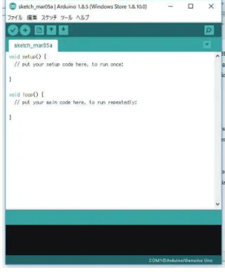
3.1 Arduino IDE 1.8.5
Arduino IDE is an open-source integrated Table 1 Data sheet of Toshiba’s TA7291P
Sign Pin Explanations
Vcc 7 Power for Logic
Vs 8 Power for Output
Vref 4 Power for Control
GND 1 GND
IN1 5 Input
IN2 6 Input
OUT1 2 Output
OUT2 10 Output
Table 2 Functions of Toshiba’s TA7291P
Input Output
IN1 IN2 OUT1 OUT2 Mode
0 0 ∞ ∞ Stop
1 0 High Low Clockwise
0 1 Low High Counter Clockwise
1 1 Low Low Break
Figure 4 Breadboard and jumper wires
Figure 5 Arduino IDE ver.1.8.5
Shinji Notsu
developing environment and runs on Windows, macOS and Linux. The latest version of it was used after being downloaded from the following URL: https://www.arduino.cc/en/main/software Processing is a programming language for Arduino. The source code is written in Processing.
It is a command-case objective language.
3.2 USB-Serial Driver: CH340
Either Windows, macOS or Linux has a USB- S e r i a l d r i v e r f o r t h e s t a n d a r d A r d u i n o microcomputer board. However, the cheaper compatible board usually uses other USB-Serial chips, in this case, CH340. Thus, we have to install its driver into the OS manually. We have to confirm the installation of the driver by seeing the device driver on Windows 10.
3.3 Installations and Configurations
First of all, we have to specify the type of Arduino and the number of the COM port on the Arduino IDE. Then we can start writing and/or modifying the source code, compiling it, and transferring the binary code.
3.4 S4A 1.6
It is not easy for students of elementary school to remember the commands and grammar of Processing language. In such a case, S4A is a very useful IDE for Brick-based visual IDE. It provides beginners with how to create codes in visual parts. It looks like Figure 6 as shown below:
4. Algorithm
First of all, students should classify the following four relation cases in which a Line Following Robot is on the line (Table 3):
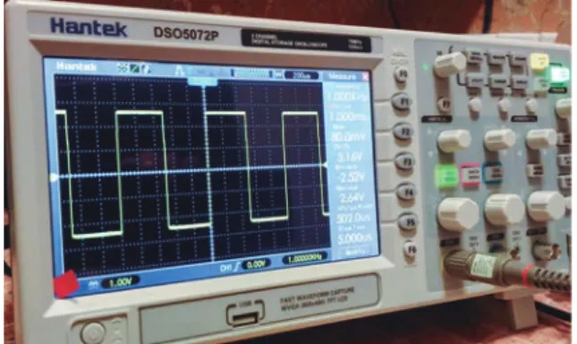
4.1 PWM to calibrate speed for both DC motors The PWM (Pulse Width Modulation) is used for controlling the speed of the DC motor. The Digital Storage Oscilloscope (DSO, Figure 7) has a lot of visualizations for change in voltage with time.
DSO enables college students and teachers to see whether their codes are correct or not.
Figure 7 DSO is used for observation of PWM Figure 6 S4A ver. 1.6
Table 3 Relationships between sensors and motors
Sensors Left Right Left Right Left Right Left Right
Threshold White White Black White White Black Black Black
Motor Clockwise Clockwise Stop Clockwise Clockwise Stop Clockwise Stop
Robot Forward Turn left Turn right Turn right
A Design and an Implementation of a Course for Learning a Line Following Robot for Students in an Elementary School, a College, and Teachers
27 4.2 Threshold to distinguish Black and White
After we code the serial console, students can simultaneously see the values of the photo reflector by the Console. They should write down the values while they put black and white papers in front of the photo reflector.
5. Learning Contents
Here follows an explanation of the contents of learning in the previous sections. The weight of contents is carefully selected for elementary school students, college students and teachers, respectively. The following sections will explain
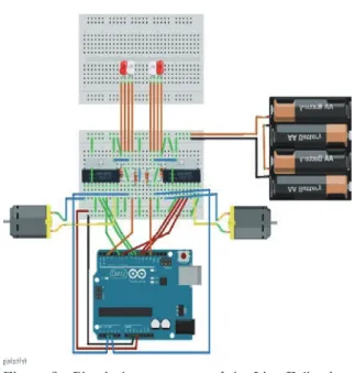
Figure 8 Physical components of the Line Following Robot
Figure 9 A Line Following Robot on a test cource Figure 10 A sample source code
Shinji Notsu
them in detail.
5.1 Hardware
Figure 8 and the Figure 9 are physical images of the whole parts for a Line Following Robot.
5.2 Software
A sample source code (Figure 10) is written in Processing language, and after a flowchart explains that the Line Following Robot can run on the black curve on a white floor.
College students wrote a source code for a Line Trace Robot. However, elementary school students only modified several parts of a sample code, especially values of both thresholds and PWMs.
6. Lectures for Students and Teachers
The learning points for students in elementary school, students in college, and teachers are summarized in Table 4.
6.1 College Students
College students studied all of the topics of Table 4 . Students were assigned to groups of eight people which tried using the PBL (Project Based Learning). They fixed several problems, such as determining parameters for the threshold of Photo reflectors, and values of PWM of DC motors.
Table 4 The coures for students and teachers
Target College
Students
Elementary School Students
Teachers
Date July 2017 through
June 2018
October 2017 through
Feburary 2018 December 26, 2017
No. of attendants 43 20 25
Grade Freshman 4th to 6th Elementary School to
High School
Size of group 7 to 8 persons 4 persons Individual
Amount of time 90 min × 8 45 min × 5 120 min × 1
Hardware
Arduino UNO 〇 × △
LBR-127HLD 〇 × △
FA-130 〇 × △
TA7291P 〇 △ 〇
Breadbords & Jumper Wires 〇 × △
Others 〇 × △
Software
Arduino IDE (Processing) 〇 × 〇
CH340 driver 〇 × 〇
S4A 〇 〇 〇
Algorithm 〇 △ 〇
PWM 〇 〇 〇
Threshold 〇 〇 〇
A Design and an Implementation of a Course for Learning a Line Following Robot for Students in an Elementary School, a College, and Teachers
29 6.2 Elementary School Students
Elementary school students only checked the values of Photo reflectors and the gaps between the robot and the course. They determined the parameter values, and after they considered the relationships between the values and phenomenon.
6.3 Teachers
The simple circuit was designed in which an Arduino nano can control both one photo reflector and one DC motor driver IC on the breadboard
(Figure 11). The author taught them two topics.
The First topic was how they should determine both the threshold of sensors and PWM value for the DC motor. The second topic was how they
could write programs in two languages, Processing and Scratch.
Finally, the author described controlling programs which were a sketch in Processing
(Figure 10) and a project in Scratch (Figure 12 and Figure 13).
7. Conclusions
First of all, the robot building is the best learning target for integrating both hardware and software. Second, software, especially programs, can absorb the imbalance among the hardware parts. Thus, students must master this to adjust the parameters by measuring the behaviors. For instance, the thresholds of both photo reflectors distinguishing between black and white on the floor, and the PWM parameter adjusting the torques of both DC motors.
References
1)Shouhei YANO and Prawet UEATRONGCHIT,
“Computer Vision Guidance of a Line Following
Figure 12 The value of Sensor is connected on D13 Figure 13 Cursor keys control DC motor in Scratch Figure 11 An Arduino can control a photo reflector
and DC motor driver IC
Shinji Notsu
Robot using Mobile Phone - Description of How to Create Machines for Contest with Thai-Nichi Institute of Technology”, Memoirs of Nagaoka National College of Technology, No. 50, (2014), pp. 87-96.
2)Arduino IDE
https://www.arduino.cc/en/main/software 3)CH340 driver
http://www.wch.cn/download/CH341SER_ZIP.html