フレーム形態と前装材料の違いがインプラント支持 ジルコニアクラウンの破壊強度に及ぼす影響
日本大学大学院歯学研究科歯学専攻
神尾 伸吾
(指導:松村 英雄 教授,小峰 太 専任講師)
1
概 要
オールセラミック修復は審美性に優れており,日常臨床において幅広く使用されて いる。なかでも二酸化ジルコニウム(以下ジルコニア)は,生体親和性に優れ,かつ 機械的強度に優れた材料であり,咬合力の負荷が大きい臼歯部領域におけるオールセ ラミック修復物にも臨床応用されている。一方で,インプラント支持のジルコニア修 復物は,自然歯を支台とする修復物と比較して,より高い頻度で前装陶材のチッピン グ(微小破折)の発生が報告されている。
前装陶材の微小破折を防止する方法として,ジルコニアフレームワークに加圧成型 セラミックを焼成するオーバープレス法,前装陶材のサポーティングエリアをジルコ ニアフレームワークに付与する方法,または前装材料として間接修復用コンポジット レジンの応用が報告されている。
これまでの研究において,間接修復用コンポジットレジンとジルコニアフレーム間 の接着強さは臨床応用可能な強度であり,さらにインプラント支持の間接修復用コン ポジットレジン前装ジルコニア修復物(以下
ZIC)の破壊強度はジルコニアオールセラミック修復物(以下
ZAC)と同程度であったと報告されている。一方,臼歯部インプラント支持の
ZACにおいて,フレームワーク形態の相違が破 壊強度に及ぼす影響について報告されている。しかし,フレームワーク形態の違いが 破壊強度に与える影響についての報告は少ないのが現状である。そこで本研究では,
ジルコニアフレームワーク形態および前装材料の違いがインプラント支持の臼歯部 ジルコニア修復物の破壊強度に及ぼす影響を評価することを目的とした。
インプラント上部構造のジルコニアフレームワーク形態は
uniform thickness(以下 UNI),anatomic(以下
ANA),supported anatomic(以下
SUP)の3条件とし,さらに
2
前装材料の違いにより
ZAC群と
ZIC群の
2群に分けた。下顎右側第一大臼歯欠損症 例を想定し,直径
5.0 mmの歯科用インプラント体を水平面に対して垂直方向に,ポ リエステル樹脂に植立した。植立後,チタン製アバットメントを,製造者指示に従い チタン製スクリューとトルクコントローラーを用いて締結圧
32 Nでインプラント体 に装着した。その後,技工用エアータービンを用いてアバットメント上面を削除し,
シリコーンインデックスを参考にアバットメントの高径を
6.0 mmに調整した。
アバットメント調整後,歯科用
CAD/CAMシステムを用いて半焼結体ジルコニアブ ロックからジルコニアフレームワークを製作した。ジルコニアフレームワークは,
UNI,ANA
および
SUPの
3形態(
n = 22)とした。
UNI形態は,ジルコニアフレームワーク
を均一な厚さ
0.5 mmとした。
ANA形態は解剖学的な形態を考慮し,前装材料を均一
な厚さ
1.2 mmとした。SUP 形態は
ANA形態と同様に前装材料を均一な厚さ
1.2 mmにし,さらに隣接面から舌側面にかけて高さ
5.0 mmの前装材料を水平面でサポート する形態を付与した。
各フレームワークは歯科用
CAD/CAMマシンを用いてジルコニアブロックから削 り出し,ジルコニア焼却炉で
1375℃,
90分間の焼結を行った。全てのジルコニアフ レームワークは,メジャリングデバイスを用いて各条件で設定した厚さであることを 確認後,光学顕微鏡下にてアバットメントとの適合を探針とシリコーン適合検査材を 用いて確認した。
その後,ジルコニアフレームワークの前装面に対して平均粒径
50 µmのアルミナ粒
子を噴射圧力
0.2 MPa,噴射口から前装面までの距離
10 mmで
20秒間の条件で,ア
ルミナブラスト処理を行った。各フレームワーク形態は,さらに
ZAC群と
ZIC群の
2群に分けた(n = 11)。
3
ZAC
群は歯冠形態製作用金型を用いて製造者指示に従い前装陶材を築盛した。ま ず,セラビアン
ZRシェードベース(SBA2)を
2層築盛し,1 層ごとに焼成後,セラ ビアン
ZRボディ(
A2B) ,セラビアン
ZRエナメル(
E2)の順に築盛,焼成した。修 復物は,製造者指示の焼成スケジュールに従い,SingleMat Porcelain Furnace で焼成し た。前装陶材焼成後,メジャリングデバイスとシリコーンインデックスを用いて修復 物の厚さを確認し,グレージングを行い,前述と同様にアバットメントとの適合を確 認した。
ZIC
群は製造者指示に従い,ジルコニア前装面に対してエステニアオペークプライ マーを用いてプライマー処理を行った。プライマー処理後,エステニア
C&Bボディ オペーク(
OA2)を
2層塗布し,
1層ごとに光重合器にて
90秒間,光重合を行った。
その後,ZAC 群と同様に歯冠形態製作用金型を使用し,エステニア
C&Bデンチン
(DA2)とエステニア
C&Bエナメル(E1) を築盛し,光重合器にて 5 分間,光重合 を行い,さらに加熱重合器にて
110℃,
15分間の加熱重合を行った。前装終了後,試 料は
ZAC群と同様の方法で前装厚さ,および適合の確認を行った。
製作した修復物の内面に,平均粒径
50 µmのアルミナ粒子を噴射圧力
0.2 MPaで
10秒間の条件でアルミナブラスト処理を行った。全ての試料は,グラスアイオノマーセ メントを用いて咬合面から
30 Nの垂直荷重を
7分間付与しアバットメントに装着さ れた。セメント硬化後,試料は
37℃精製水中に
24時間保管後,破壊強度試験を行っ た。
破壊強度試験は万能試験機を用いて,クロスヘッドスピード毎分
0.5 mmの条件下
で行い,直径
6.0 mmのステンレススチールボールを用いて,咬合面に対して垂直方
向に静的圧縮荷重を試料の破壊に至るまで負荷した。その際,咬合力を均等に分散す
4
るために, 厚さ
1.0 mmの鉛箔をステンレススチールボールと試料の間に介在させた。
破壊強度値は最大荷重値から
10 %が減少した時点における圧縮荷重値(N)とした。統計学的検討は,
Levene検定を行ったところ等分散性が得られなかったため,同一 前装材料におけるフレームワーク形態間の違いを評価するために
Kruskal-Wallis検定 を行い,その結果を基に,同一前装材料における
3条件間の違いを比較するために
Bonferroni
の多重比較を用いた。また,同一フレームワーク形態における
ZAC群と
ZIC
群間の比較には
Mann-Whitney U検定を用いた。全ての検定は有意水準
0.05の条 件で行った。
試験後の破壊様式は光学顕微鏡を用い,前装材料内の破壊とフレームワークに及ぶ 破壊に分類した。さらに,試料表面に対して
30秒間オスミウム蒸着を行い,加速電
圧
15 kVの条件で走査電子顕微鏡(以下
SEM)を用いて試料表面の観察を行った。UNI,ANA
および
SUP形態の破壊強度の平均値はそれぞれ
ZAC群で
3.78,6.01,6.50 kN
,
ZIC群で
3.15,
5.65,
5.83 kNであった。
ZAC群および
ZIC群ともに,
UNI形態が他の
2つのフレームワーク形態と比較して有意に低い破壊強度を示した。 また,
各フレームワーク形態について
ZAC群と
ZIC群の間に統計学的有意差は認められな かった。
試験後の破壊様式は,
ZAC群はフレームワーク形態にかかわらず,フレームワーク に及ぶ破壊を多数認めたが,ZIC 群は約半数で前装材料内の破壊を認めた。また,前 装材料内の破壊において,
ZAC群および
ZIC群ともに,
UNI形態では咬合面からク ラウンマージンにかけて前装材料の破壊が観察された。一方,
ANA形態と
SUP形態 では試料の辺縁隆線と咬頭に前装材料の破壊が観察された。
SEM
観察像において,ZAC 群および
ZIC群の前装材料内の破壊と判定された試料
5
では,いずれの群においてもジルコニア前装面には陶材,もしくは間接修復用コンポ ジットレジンと考えられる残留物が観察された。また,フレームワークに及ぶ破壊と 判定された試料では,いずれの群においても,ジルコニアフレームワークと前装材料 は緊密に接触しており,界面における前装材料の剥離は認められなかった。
フレームワーク形態と前装材料の違いが,インプラント支持の臼歯部ジルコニア修 復物の破壊強度に及ぼす影響を検討した結果,本研究の範囲内において以下の結論を 得た。
1.
前装材料の厚さを均一にすることとジルコニアフレームワークに適切なサポー ト形態を付与することは,ジルコニアオールセラミック修復物とインプライト 支持の臼歯部間接修復用コンポジットレジン前装ジルコニア修復物の破壊強度 を向上させた。
2.
インプラント支持の臼歯部間接修復用コンポジットレジン前装ジルコニア修復 物は,ジルコニアオールセラミック修復物と同程度の破壊強度を示した。
なお,本論文は
Kamio S, Komine F, Taguchi K, Iwasaki T, Blatz MB, Matsumura H (2014) Effects of framework design and layering material on fracture strength of implant- supported zirconia-based molar crowns. Clinical Oral Implants Research 2014, doi:10.1111/clr.12468.
を基幹論文とし,さらにジルコニア修復物の破壊様式を評価する新
たなデータを加えることによって総括したものである。
6
緒 言
オールセラミック修復は審美性に優れており,日常臨床において幅広く使用されて いる。なかでも二酸化ジルコニウム(以下ジルコニア)は,生体親和性に優れ,かつ 機械的強度に優れた材料であり(曲げ強さ > 1 GPa;破壊靱性,
KIC = 9~10 MN/m3/2)
(Christel et al. 1989) ,咬合力の負荷が大きい臼歯部領域におけるオールセラミック修 復物にも臨床応用されている。ジルコニアをフレームワークとしたクラウンやブリッ ジなどの固定性補綴装置は,中・長期的な臨床研究において臨床成績が報告されてい るが,自然歯を支台とするジルコニアオールセラミック修復物において前装陶材のチ ッピング(微小破折)の発生率は
6~
25 %と報告されている(
Vult von Steyern et al. 2005;Edelhoff et al. 2008; Tinschert et al. 2008; Sailer et al. 2009a; Roediger et al. 2010
) 。
インプラント支持の修復物においてジルコニアをアバットメントあるいはフレー ムワークの材料として用いた場合に,自然歯を支台とする修復物と比較して,より高
い頻度(
10~
40 %)での前装陶材の微小破折の発生が報告されている(
Larsson et al.2006; Nothdurft & Pospiech 2009; Sailer et al. 2009b; Larsson & Vult von Steyern 2010)
。そ の原因として,歯科用インプラントは歯根膜を介在させず骨に直接結合し,インプラ ント支持の修復物に対して自然歯よりも大きな咬合圧がかかるためと考えられてい る(Hämmerle et al. 1995; Çiftçi & Canay 2000)。
前装陶材の微小破折を防止する方法として,前装材料の均一性と密度を向上させる 目的でジルコニアフレームワークに加圧成型セラミックを焼成するオーバープレス 法(
Beuer et al. 2010; Chaar et al. 2013) ,適切な前装陶材の厚さと解剖学的形態を考慮 して前装陶材のサポーティングエリアをジルコニアフレームワークに付与する方法
(Marchack et al. 2008; Larsson et al. 2012) ,または前装材料として間接修復用コンポジ
7
ットレジンの応用(Kobayashi et al. 2009; Taguchi et al. 2014)が報告されている。これ までの研究において,間接修復用コンポジットレジンとジルコニアフレームワーク間 の接着強さは臨床応用可能な強度であり(
Kobayashi et al. 2009; Komine et al. 2013) , さらにインプラント支持の間接修復用コンポジットレジン前装ジルコニア修復物(以
下
ZIC)の破壊強度はジルコニアオールセラミック修復物(以下ZAC)と同程度であったと報告されている(
Taguchi et al. 2014) 。
一方,臼歯部インプラント支持の
ZACにおいて,フレームワーク形態の相違が破 壊強度に及ぼす影響について検討したところ,前装材料の厚さを均一に設計したフレ ームワークを用いた修復物の方が有意に高い破壊強度を示すと報告されている
(
Lorenzoni et al. 2010; Kokubo et al. 2011; Larsson et al. 2012) 。しかし,フレームワー ク形態の違いが破壊強度に与える影響についての報告は少ないのが現状である。そこ で本研究では,ジルコニアフレームワーク形態および前装材料の違いがインプラント 支持の臼歯部ジルコニア修復物の破壊強度に及ぼす影響を評価することを目的とし た。
材料および方法
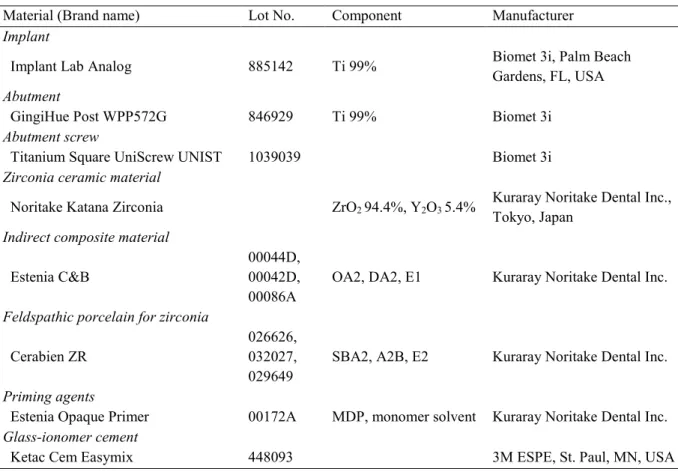
本研究で使用した材料を
Table 1に示す。インプラント上部構造のジルコニアフレ ームワーク形態は
uniform thickness(以下
UNI),
anatomic(以下
ANA),
supportedanatomic
(以下
SUP)の
3条件とし,さらに前装材料の違いにより
ZAC群と
ZIC群
の
2群に分けた。下顎右側第一大臼歯欠損症例を想定し,直径
5.0 mmの歯科用イン
プラント体(Implant Lab Analog, Biomet 3i)を水平面に対して垂直方向に,ヒト皮質
骨に近似した弾性率を有するポリエステル樹脂(
Technovit 4000, Heraeus Kulzer)に植
立した(Strub & Gerds 2003) 。植立は,内径
2.0 cmのプラスチックホルダー(Plastic
8
Ring, Sankei)内にインプラント体を保持し,第1スレッドまでポリエステル樹脂を注
入し硬化させた。その後,高径
7.0 mm,プラットフォームの直径5.0 mm,幅7.5 mm,ラウンデッドショルダーの幅
0.8 mmのチタン製アバットメント(
GingiHue Post WPP572G, Biomet 3i)を,製造者指示に従いチタン製スクリュー(Titanium Square UniScrew UNIST, Biomet 3i)とトルクコントローラー(Torque Driver HTD-C, Biomet 3i)を用いて締結圧
32 Nでインプラント体に装着した。その後,技工用エアータービン
(Presto Aqua, Nakanishi Inc.)とダイヤモンドポイント(FG 106RD, Shofu Inc.)を用い てアバットメント上面を削除し,シリコーンインデックスを参考にアバットメントの
高径を
6.0 mmに調整した。アバットメントはシリコーンホイール(
Silicone Wheel PType, Shofu Inc.
)を用いて研磨した。
アバットメント調整後,歯科用コンピュータ支援設計・コンピュータ支援製造
(CAD/CAM)システム(Katana, Kuraray Noritake Dental Inc.)を用いて半焼結体ジル コニアブロック(
Noritake Katana Zirconia, Kuraray Noritake Dental Inc.)からジルコニ アフレームワークを製作した。ジルコニアフレームワークは,
UNI,ANAおよび
SUPの
3形態(n = 22)とした(Fig. 1) 。
UNI
形態は,ジルコニアフレームワークの軸面と咬合面を均一な厚さ
0.5 mmとし た(Fig. 1a) 。アバットメント形態は計測機器(Dental Scanner SC-3, Kuraray Noritake
Dental Inc.)にて読み取り後,歯科用 CAD/CAM
システムを用いてフレームワーク形
態のデータを作成した。
ANA
形態は解剖学的な形態を考慮し,前装材料を均一な厚さ
1.2 mmとした(
Fig.1b)。前装材料の厚さを均一にするために,陶材焼付金属冠修復と同様にフルカント
ゥアのろう型からカットバックすることによって外形を製作し,アバットメントおよ
9
びろう型の形態を計測機器で読み取り,フレームワーク形態のデータを作成した。
SUP
形態は
ANA形態と同様に前装材料を均一な厚さ
1.2 mmにし,さらに隣接面 から舌側面にかけて高さ
5.0 mmの前装材料を水平面でサポートする形態を付与した
(Fig. 1c) 。このフレームワーク形態のデータは
ANA形態と同様の手順で作成した。
各フレームワークは,フィニッシュライン以外の部分に
40 μmのセメントスペース を設定し,歯科用
CAD/CAMマシン(
Katana DWX-50N, Kuraray Noritake Dental Inc.) を用いてジルコニアブロックから削り出し,ジルコニア焼却炉(Katana F-1, Kuraray
Noritake Dental Inc.)で1375 °C,90 分間の焼結を行った。
全てのジルコニアフレームワークは,メジャリングデバイス(
YDM)を用いて各条 件で設定した厚さであることを確認後,光学顕微鏡(
Stemi DV4, Carl Zeiss Co., Ltd.) 下にてアバットメントとの適合を探針(Single-end Explorer, YDM)とシリコーン適合 検査材(Fit Checker, GC Corp.)を用いて確認した。
その後,ジルコニアフレームワークの前装面に対して平均粒径
50 μmのアルミナ粒 子(Hi-Aluminas, Shofu Inc.)を噴射圧力
0.2 MPa,噴射口から前装面までの距離10 mmで
20秒間の条件で,アルミナブラスト処理を行った。各フレームワーク形態は,さ らに
ZAC群と
ZIC群の
2群に分けた(
n = 11) 。
ZAC
群は高径
8.0 mm,近遠心径11.0 mm,頬舌径10.5 mmの歯冠形態(Nelson &
Ash 2010)になるように,歯冠形態製作用金型(K854-02-000E, Tokyo Giken Inc.)
(Fig.
2
)を用いて製造者指示に従い前装陶材(セラビアン
ZR, Kuraray Noritake Dental Inc.) を築盛した。まず,セラビアン
ZRシェードベース(
SBA2)を
2層築盛し,
1層ごと に焼成後,セラビアン
ZRボディ(A2B) ,セラビアン
ZRエナメル(E2)の順に築盛,
焼成した。前装陶材は粉末と専用液(Meister Liquid, Kuraray Noritake Dental Inc.)を混
10
和し,得られた陶材泥をフレームワークに築盛し,超音波バイブレータ(Ceracon II,
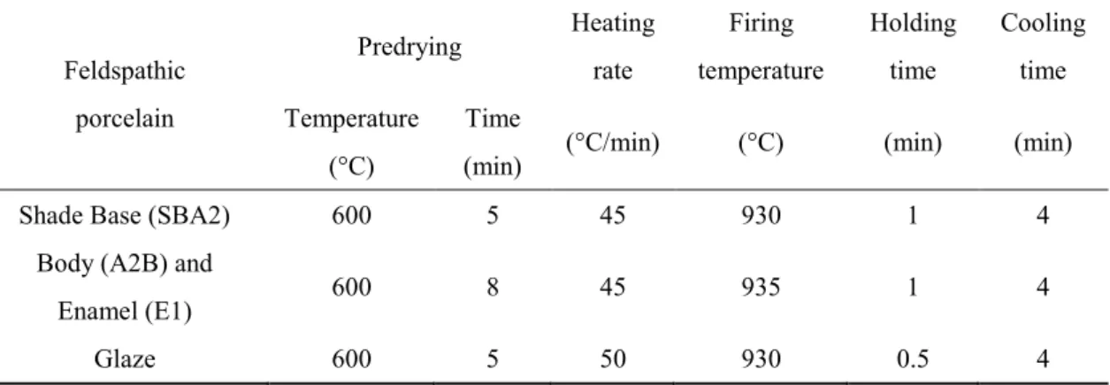
Shofu Inc.)を用いてコンデンスした。修復物は,製造者指示の焼成スケジュールに従い,
SingleMat Porcelain Furnace(
Shofu Inc.)で焼成した(
Table 2)。前装陶材焼成後,
メジャリングデバイスとシリコーンインデックスを用いて修復物の厚さを確認し,グ レージングを行い(Table 2) ,前述と同様にアバットメントとの適合を確認した。
ZIC
群は製造者指示に従い,ジルコニア前装面に対してエステニアオペークプライ マー(Kuraray Noritake Dental Inc.)を用いてプライマー処理を行った。プライマー処 理後,エステニア
C&B(Kuraray Noritake Dental Inc.)ボディオペーク(OA2)を2層 塗布し,
1層ごとに光重合器(
α-light II, J. Morita Corp.)にて
90秒間,光重合を行っ た。その後,
ZAC群と同様に歯冠形態製作用金型(
Fig. 2)を使用し,エステニア
C&Bデンチン(DA2)とエステニア
C&Bエナメル(E1)を築盛し,光重合器にて
5分間,
光重合を行い,さらに加熱重合器(KL-310, J. Morita Corp.)にて
110℃,15 分間の加 熱重合を行った。前装終了後,試料は
Polishing Instrument Kit(
Kuraray Noritake DentalInc.)にて研磨を行い,ZAC
群と同様の方法で前装厚さ,および適合の確認を行った。
製作した修復物の内面に,平均粒径
50 µmのアルミナ粒子を噴射圧力
0.2 MPaで
10秒間の条件でアルミナブラスト処理を行った。全ての試料は,グラスアイオノマーセ メント(Ketac Cem Easymix, 3M ESPE AG)を用いて咬合面から
30 Nの垂直荷重を
7分間付与しアバットメントに装着した。セメント硬化後,試料は
37℃精製水中に
24時間保管後,破壊強度試験を行った。
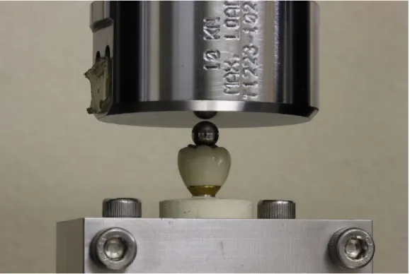
破壊強度試験は万能試験機(
Type 5567, Instron Corp.)を用いて,クロスヘッドスピ
ード毎分
0.5 mmの条件で行い,直径
6.0 mmのステンレススチールボールを用いて,
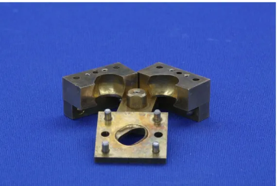
咬合面に対して垂直方向に静的圧縮荷重を試料の破壊に至るまで負荷した(Fig. 3)。
11
なお,ステンススチールボールの直径は,これまでの論文で推奨されている直径
5~10 mm(Kim et al. 2008; Alhasanyah et al. 2013)を参考に決定した。また,咬合力を均
等に分散するために,厚さ
1.0 mmの鉛箔(
Dentaurum, Ispringen)をステンレススチー ルボールと試料の間に介在させた。破壊強度値は最大荷重値から
10 %が減少した時点における圧縮荷重値(N)とした(Lehmann et al. 2004) 。
統計学的検討は,統計学的分析ソフトウェア(
SPSS version 19.0, SPSS, Inc.)を用い て行った。まず,
Levene検定を行ったところ等分散性が得られなかったため,同一前 装材料におけるフレームワーク形態間の違いを評価するために
Kruskal-Wallis検定を 行い,その結果を基に,同一前装材料における
3条件間の違いを比較するために
Bonferroni
の多重比較を用いた。また,同一フレームワーク形態における
ZAC群と
ZIC
群間の比較には
Mann-Whitney U検定を用いた。全ての検定は有意水準
0.05の条 件で行った。
試験後の破壊様式は
32倍の光学顕微鏡(
Stemi DV4, Carl Zeiss Co.)を用い,前装材 料内の破壊とフレームワークに及ぶ破壊に分類した。さらに,試料表面に対して
30秒 間オスミウム蒸着(HPC-IS, Vacuum Device Inc.)を行い,加速電圧
15 kVの条件で走 査電子顕微鏡(
S-4300, Hitachi High Technologies Co. Ltd., 以下SEM)を用いて試料表面 の観察を行った。
成 績
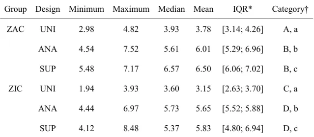
破壊強度と統計学的検討の結果を
Table 3に示す。
UNI,ANAおよび
SUP形態の破
壊強度の平均値はそれぞれ
ZAC群で
3.78,6.01,6.50 kN,ZIC群で
3.15,5.65,5.83 kNであった。
ZAC群および
ZIC群ともに,
UNI形態が他の
2つのフレームワーク形
態と比較して有意に低い破壊強度を示した。また,各フレームワーク形態について
12
ZAC
群と
ZIC群の間に統計学的有意差は認められなかった。
破壊強度試験後の破壊様式評価の結果を
Table 4に示す。ZAC 群はフレームワーク 形態にかかわらず,フレームワークに及ぶ破壊を多数認めたが,
ZIC群は約半数で前 装材料内の破壊を認めた。また,前装材料内の破壊において,
ZAC群および
ZIC群と もに,
UNI形態では咬合面からクラウンマージンにかけて前装材料の破壊が観察され た。一方,
ANA形態と
SUP形態では試料の辺縁隆線と咬頭に前装材料の破壊が観察 された。
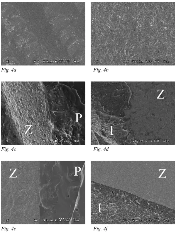
SEM
観察像において,歯科用
CAD/CAMマシンで削り出された直後のジルコニア フレームワークの表面では,バーによって作られた傷が認められた(
Fig. 4a) 。また,
アルミナブラスト処理後のジルコニア表面は,粗造面を呈していた(
Fig. 4b) 。
ZAC群 および
ZIC群の前装材料内の破壊と判定された試料の
SEM観察像では,いずれの群 においてもジルコニア前装面には陶材,もしくは間接修復用コンポジットレジンと考 えられる残留物が観察された(
Fig. 4c, d) 。また,フレームワークに及ぶ破壊と判定さ れた試料の
SEM観察像では,いずれの群においても,ジルコニアフレームワークと 前装材料は緊密に接触しており,界面における前装材料の剥離は認められなかった
(
Fig. 4e, f) 。
考 察
本研究の結果,
ZAC群および
ZIC群ともに,
UNI形態が他の
2つのフレームワー
ク形態と比較して有意に低い破壊強度を示したことから,フレームワーク形態の相違
はインプラント支持のジルコニア修復物の破壊強度に影響を与えることが明らかと
なった。一方,各フレームワーク形態について
ZAC群と
ZIC群の間に統計学的有意
差は認められなかったことから,前装材料の相違はジルコニア修復物の破壊強度に影
13
響を及ぼさないことが示された。また,ジルコニア修復物の破壊強度の平均は全ての 条件において
3.0 kNを越えており, 生理的な臼歯部の最大咬合力である
0.88 kN(Bates
et al. 1975; Kiliaridis et al. 1993)より高かった。
本研究において,インプラント支持の臼歯部ジルコニア修復物におけるフレームワ ーク形態の影響を評価した結果,ZAC 群および
ZIC群ともに,解剖学的な形態を考 慮し前装材料の厚さを均一にしたフレームワーク形態は,フレームワークの厚さを均 一にした形態より高い破壊強度を示した。この結果は,解剖学的な形態を考慮してフ レームワークを設計することにより,ジルコニアフレームワークによる前装材料の適 切な支持が得られたためと考えられる(
Rosentritt et al. 2009; Kokubo et al. 2011; Larssonet al. 2012
)。また,ジルコニアは熱伝導率が低いため,厚い前装陶材の存在が,破壊
強度の低下に影響すると考えられる(Swain 2009; Larsson et al. 2012)。さらに,舌側面 に前装材料のサポーティングエリアを付与した
SUP形態は
ZAC群と
ZIC群におい て,
ANA形態と同等の破壊強度を示した。以上のように,前装材料の厚さを均一にす るとともに,ジルコニアフレームワークによる咬合面の支持を得ることが,十分な破 壊強度を発揮するために重要であることが明らかとなった。
ZIC
群の破壊強度は,全てのフレームワーク形態において
ZAC群と同等であった。
これは,前装陶材と比較して間接修復用コンポジットレジンは弾性率が低いために
(Çiftçi & Canay 2000),荷重を緩和する能力が高かったためと考えられた。したがっ て,これまでの研究結果(
Oderich et al. 2012; Taguchi et al. 2014)と同様に,間接修復 用コンポジットレジンは前装材料として推奨できることが示された。
試験後の破壊様式は,ZAC 群において試料の多数がジルコニアフレームワークに
達する破壊を示したが,ZIC 群においては,試料の約半数が前装材料内の破壊を示し
14
た。この違いには,前装陶材と間接修復用コンポジットレジンのジルコニアフレーム ワークに対する接着強さの違い(Kobayashi et al. 2009; Saito et al. 2010)が影響してい ると考えられる。
間接修復用コンポジットレジンは,インプラント支持の修復物を含めて固定性補綴 装置において広く使用されるようになってきた。本研究によって,インプラント修復 物におけるジルコニアフレームワークの前装材料としての臨床応用の可能性が示さ れた。一方で,咬合面へのコンポジットレジンの適応は,破折,咬耗あるいは審美性 の不良などを生じることが懸念される(Lindquist et al. 1987; Carlson & Carlsson 1994;
Lekholm et al. 1994
) 。
本研究における
SUP形態では,舌側においてジルコニア面が口腔内に露出してい るが,ジルコニアは水分の存在で低温劣化(LTD)する傾向があることが知られてい る(Lughi & Sergo 2010) 。長期間の水分や血液との接触は,立方晶から単斜晶への相 転移を誘導するとされている。
LTDによる相転移に伴う体積変化は補償されないため,
ジルコニアの機械的性質を低下させ,破壊を引き起こすと報告されている(Lughi &
Sergo 2010)
。一方,水分の存在はジルコニアの機械的性質に影響しないとする報告も
ある(
Curtis et al. 2006; Papanagiotou et al. 2006; Alghazzawi et al. 2012) 。本研究では,
試料に対して加速劣化あるいは動的負荷を加えることなく,破壊強度を測定した。今
後,インプラント支持の間接修復用コンポジットレジン前装ジルコニア修復物の長期
安定性に関して明確な示唆を得るためには,加速劣化試験あるいは臨床研究が必要で
あると考えられる。
15
結 論
フレームワーク形態と前装材料の違いが,インプラント支持の臼歯部ジルコニア修 復物の破壊強度に及ぼす影響を検討した結果,本研究の範囲内において以下の結論を 得た。
1.
前装材料の厚さを均一にすることとジルコニアフレームワークに適切なサポー ト形態を付与することは,ジルコニアオールセラミック修復物とインプラント 支持の臼歯部間接修復用コンポジットレジン前装ジルコニア修復物の破壊強度 を向上させた。
2.
インプラント支持の臼歯部間接修復用コンポジットレジン前装ジルコニア修復 物は,ジルコニアオールセラミック修復物と同程度の破壊強度を示した。
謝 辞
本研究の一部は,私立大学経常費特別補助大学院高度化推進特別経費(2013 年度お
よび
2014年度)の補助によって行われた。
16
文 献
Alghazzawi, T.F., Lemons, J., Liu, P.R., Essig, M.E., Bartolucci, A.A. & Janowski, G.M. (2012) Influence of low-temperature environmental exposure on the mechanical properties and structural stability of dental zirconia. Journal of Prosthodontics 21: 363-369.
Alhasanyah, A., Vaidyanathan, T.K. & Flinton, R.J. (2013) Effect of core thickness differences on post-fatigue indentation fracture resistance of veneered zirconia crowns. Journal of Prosthodontics 22: 383-390.
Bates, J.F., Stafford, G.D. & Harrison, A. (1975) Masticatory function -a review of the literature (II) Speed of movement of the mandibular, rate of chewing and forces developed in chewing.
Journal of Oral Rehabilitation 2: 349-361.
Beuer, F., Stimmelmayr, M., Gernet, W., Edelhoff, D., Güh, J.F. & Naumann, M. (2010) Prospective study of zirconia-based restorations: 3-year clinical results. Quintessence International 41: 631-637.
Carlson, B. & Carlsson, G.E. (1994) Prosthodontic complications in osseointegrated dental implant treatment. The International Journal of Oral & Maxillofacial Implants 9: 90-94.
Chaar, M.S., Witkowski, S., Strub, J.R. & Att, W. (2013) Effect of veneering technique on the fracture resistance of zirconia fixed dental prostheses. Journal of Oral Rehabilitation 40: 51- 59.
Christel, P., Meunier, A., Heller, M., Torre, J.P. & Peille, C.N. (1989) Mechanical properties and short-term in-vivo evaluation of yttrium-oxide-partially-stabilized zirconia. Journal of Biomedical Materials Research 23: 45-61.
Çiftçi, Y. & Canay, S. (2000) The effect of veneering materials on stress distribution in implant- supported fixed prosthetic restorations. The International Journal of Oral & Maxillofacial Implants 15: 571-582.
Curtis, A.R., Wright, A.J. & Fleming, G.J. (2006) The influence of surface modification
17
techniques on the performance of a Y-TZP dental ceramic. Journal of Dentistry 34: 195-206.
Edelhoff, D., Florian, B., Florian, W. & Johnen, C. (2008) HIP zirconia fixed partial dentures–
clinical results after 3 years of clinical service. Quintessence International 39: 459-471.
Hämmerle, C.H., Wagner, D., Brägger, U., Lussi, A., Karayiannis, A., Joss, A. & Lang, N.P.
(1995) Threshold of tactile sensitivity perceived with dental endosseous implants and natural teeth. Clinical Oral Implants Research 6: 83-90.
Kiliaridis, S., Kjellberg, H., Wenneberg, B. & Engström, C. (1993) The relationship between maximal bite force, bite force endurance, and facial morphology during growth. A cross- sectional study. Acta Odontologica Scandinavica 51: 323-331.
Kim, J.H., Kim, J.W., Myoung, S.W., Pines, M. & Zhang, Y. (2008) Damage maps for layered ceramics under simulated mastication. Journal of Dental Research 87: 671-675.
Kobayashi, K., Komine, F., Blatz, M.B., Saito, A., Koizumi, H. & Matsumura, H. (2009) Influence of priming agents on the short-term bond strength of an indirect composite veneering material to zirconium dioxide ceramic. Quintessence International 40: 545-551.
Kokubo, Y., Tsumita, M., Kano, T. & Fukushima, S. (2011) The influence of zirconia coping designs on the fracture load of all-ceramic molar crowns. Dental Materials Journal 30: 281- 285.
Komine, F., Kobayashi, K., Blatz, M.B., Fushiki, R., Koizuka, M., Taguchi, K. & Matsumura, H. (2013) Durability of bond between an indirect composite veneering material and zirconium dioxide ceramics. Acta Odontologica Scandinavica 71: 457-463.
Larsson, C., Vult von Steyern, P., Sunzel, B. & Nilner, K. (2006) All-ceramic two- to five-unit implant-supported reconstructions. A randomized, prospective clinical trial. Swedish Dental Journal 30: 45-53.
Larsson, C. & Vult von Steyern, P. (2010) Five-year follow-up of implant-supported Y-TZP and ZTA fixed dental prostheses. A randomized, prospective clinical trial comparing two
18
different material systems. The International Journal of Prosthodontics 23: 555-561.
Larsson, C., El Madhoun, S., Wennerberg, A. & Vult von Steyern, P. (2012) Fracture strength of yttria-stabilized tetragonal zirconia polycrystals crowns with different design: an in vitro study. Clinical Oral Implants Research 23: 820-826.
Lehmann, F., Eickemeyer, G. & Rammelsberg, P. (2004) Fracture resistance of metal-free composite crowns-effects of fiber reinforcement, thermal cycling, and cementation technique. The Journal of Prosthetic Dentistry 92: 258-264.
Lekholm, U., Steenberghe, D.v., Herrmann, I., Bolender, C., Folmer, T., Gunne, J., Henry, P., Higuchi, K., Laney, W.R. & Lindén, U. (1994) Osseointegrated implants in the treatment of partially edentulous jaws: a prospective 5-year multicenter study. The International Journal of Oral & Maxillofacial Implants 6: 627-635.
Lindquist, L.W., Carlsson, G.E. & Glantz, P.O. (1987) Rehabilitation of the edentulous mandible with a tissue-integrated fixed prosthesis: a six-year longitudinal study.
Quintessence International 18: 89-96.
Lorenzoni, F.C., Martins, L.M., Silva, N.R., Coelho, P.G., Guess, P.C., Bonfante, E.A., Thompson, V.P. & Bonfante, G. (2010) Fatigue life and failure modes of crowns systems with a modified framework design. Journal of Dentistry 38: 626-634.
Lughi, V. & Sergo, V. (2010) Low temperature degradation -aging- of zirconia: A critical review of the relevant aspects in dentistry. Dental Materials 26: 807-820.
Marchack, B.W., Futatsuki, Y., Marchack, C.B. & White, S.N. (2008) Customization of milled zirconia copings for all-ceramic crowns: a clinical report. The Journal of Prosthetic Dentistry 99: 169-173.
Nelson, S.J. & Ash, M.M. (2010) Wheeler's Dental anatomy, physiology, and occlusion. In: The permanent mandibular molars, 9th edition, 189-207. Philadelphia: Saunders.
Nothdurft, F.P. & Pospiech, P.R. (2009) Zirconium dioxide implant abutments for posterior
19
single-tooth replacement: first results. Journal of Periodontology 80: 2065-2072.
Oderich, E., Boff, L.L., Cardoso, A.C. & Magne, P. (2012) Fatigue resistance and failure mode of adhesively restored custom implant zirconia abutments. Clinical Oral Implants Research 23: 1360-1368.
Papanagiotou, H.P., Morgano, S.M., Giordano, R.A. & Pober, R. (2006) In vitro evaluation of low-temperature aging effects and finishing procedures on the flexural strength and structural stability of Y-TZP dental ceramics. The Journal of Prosthetic Dentistry 96: 154- 164.
Roediger, M., Gersdorff, N., Huels, A. & Rinke, S. (2010) Prospective evaluation of zirconia posterior fixed partial dentures: four-year clinical results. The International Journal of Prosthodontics 23: 141-148.
Rosentritt, M., Steiger, D., Behr, M., Handel, G. & Kolbeck, C. (2009) Influence of substructure design and spacer settings on the in vitro performance of molar zirconia crowns. Journal of Dentistry 37: 978-983.
Sailer, I., Gottner, J., Känel, S. & Hämmerle, C.H. (2009a) Randomized controlled clinical trial of zirconia-ceramic and metal-ceramic posterior fixed dental prostheses: a 3-year follow-up.
The International Journal of Prosthodontics 22: 553-560.
Sailer, I., Philipp, A., Zembic, A., Pjetursson, B.E., Hämmerle, C.H. & Zwahlen, M. (2009b) A systematic review of the performance of ceramic and metal implant abutments supporting fixed implant reconstructions. Clinical Oral Implants Research 20 Suppl 4: 4-31.
Saito, A., Komine, F., Blatz, M.B. & Matsumura, H. (2010) A comparison of bond strength of layered veneering porcelains to zirconia and metal. The Journal of Prosthetic Dentistry 104:
247-257.
Strub, J.R. & Gerds, T. (2003) Fracture strength and failure mode of five different single-tooth implant-abutment combinations. The International Journal of Prosthodontics 16: 167-171.
20
Swain, M.V. (2009) Unstable cracking (chipping) of veneering porcelain on all-ceramic dental crowns and fixed partial dentures. Acta Biomaterialia 5: 1668-1677.
Taguchi, K., Komine, F., Fushiki, R., Blatz, M.B., Kamio, S. & Matsumura, H. (2014) Fracture resistance of single-tooth implant-supported zirconia-based indirect composite-layered molar restorations. Clinical Oral Implants Research 25: 983-991.
Tinschert, J., Schulze, K.A., Natt, G., Latzke, P., Heussen, N. & Spiekermann, H. (2008) Clinical behavior of zirconia-based fixed partial dentures made of DC-Zirkon: 3-year results.
The International Journal of Prosthodontics 21: 217-222.
Vult von Steyern, P., Carlson, P. & Nilner, K. (2005) All-ceramic fixed partial dentures designed according to the DC-Zirkon technique. A 2-year clinical study. Journal of Oral Rehabilitation 32: 180-187.
表および図
Table 1. Materials assessed in the present study
Material (Brand name) Lot No. Component Manufacturer
Implant
Implant Lab Analog 885142 Ti 99% Biomet 3i, Palm Beach
Gardens, FL, USA Abutment
GingiHue Post WPP572G 846929 Ti 99% Biomet 3i
Abutment screw
Titanium Square UniScrew UNIST 1039039 Biomet 3i
Zirconia ceramic material
Noritake Katana Zirconia ZrO2 94.4%, Y2O3 5.4% Kuraray Noritake Dental Inc., Tokyo, Japan
Indirect composite material Estenia C&B
00044D, 00042D, 00086A
OA2, DA2, E1 Kuraray Noritake Dental Inc.
Feldspathic porcelain for zirconia Cerabien ZR
026626, 032027, 029649
SBA2, A2B, E2 Kuraray Noritake Dental Inc.
Priming agents
Estenia Opaque Primer 00172A MDP, monomer solvent Kuraray Noritake Dental Inc.
Glass-ionomer cement
Ketac Cem Easymix 448093 3M ESPE, St. Paul, MN, USA
Table 2. Firing schedules of feldspathic porcelain based on manufacturer's recommendations
Feldspathic porcelain
Predrying Heating rate
Firing temperature
Holding time
Cooling time Temperature
(°C)
Time
(min) (°C/min) (°C) (min) (min)
Shade Base (SBA2) 600 5 45 930 1 4
Body (A2B) and
Enamel (E1) 600 8 45 935 1 4
Glaze 600 5 50 930 0.5 4
Table 3. Results of fracture strength (kN) testing
Group Design Minimum Maximum Median Mean IQR* Category†
ZAC UNI 2.98 4.82 3.93 3.78 [3.14; 4.26] A, a
ANA 4.54 7.52 5.61 6.01 [5.29; 6.96] B, b SUP 5.48 7.17 6.57 6.50 [6.06; 7.02] B, c ZIC UNI 1.94 3.93 3.60 3.15 [2.63; 3.70] C, a ANA 4.44 6.97 5.73 5.65 [5.52; 5.88] D, b SUP 4.12 8.48 5.37 5.83 [4.80; 6.94] D, c ZAC: zirconia-based all-ceramic restorations, ZIC: zirconia-based restorations with an indirect composite material layered onto a zirconia framework, UNI: uniform-thickness design, ANA: anatomic design, SUP: supported anatomic design.
* Interquartile range.
†Identical uppercase letters indicate that the values are not statistically different between each framework design for the identical layering material (Mann-Whitney U- test with a Bonferroni correction, P > 0.05).
Identical lowercase letters indicate that the values are not statistically different between the ZAC and ZIC groups for the identical framework design (Mann-Whitney U-test, P >
0.05).
Table 4. Fracture mode after fracture resistance testing Group Design Layer fracture
(fracture locations)
Framework fracture
ZAC UNI 3
(from occlusal surface to crown margin; 3)
8
ANA 2
(marginal ridge; 1, cusp; 1)
9
SUP 0 11
ZIC UNI 6
(from occlusal surface to crown margin; 6)
5
ANA 6
(marginal ridge; 3, cusp; 3)
5
SUP 6
(marginal ridge; 4, cusp; 2)
5
ZAC: zirconia-based all-ceramic restorations, ZIC: zirconia-based restorations with an indirect composite material layered onto a zirconia framework, UNI: uniform-thickness design, ANA: anatomic design, SUP: supported anatomic design.
Fig. 1. Cross-sections of framework designs for a single-tooth implant-supported restoration. a: UNI design, b: ANA design, and c: SUP design. (unit: mm)
Fig. 2. A photograph of the index used to standardize the dimensions of restorations.
Fig. 3. A photograph of the apparatus used for fracture-resistance testing shows the position of the stainless-steel ball and tin foil at loading onset.
Fig. 4a Fig. 4b
Fig. 4c Fig. 4d
Fig. 4e Fig. 4f
Fig. 4. SEM image of representative zirconia surfaces (original magnification × 600);
(a) as milled, (b) after airborne-particle abrasion, (c, e) a ZAC group specimen after fracture testing, (d, f) a ZIC group specimen after fracture testing. Z: zirconia framework, P: porcelain, I: indirect composite.