corresponding author: [email protected]
Department of Computer and Communication, Faculty of Engineering Fukuoka Institute of Technology, 3-30-1 Wajiro, Higashi-ku, Fukuoka 811-0295, JAPAN
Research Center for Explosion Safety, National Institute of Advanced Industrial Science and Technology, 16-1 Onogawa, Tsukuba, Ibaraki 305-8569, JAPAN
Received: May 27, 2005 Accepted: October 12, 2005
Abstract
We have studied pulse laser ablation of ground glass surface by focusing a laser pulse through glass plate from rear side.
Ablation process has been observed by high speed framing camera. Burst of small fragments of glass has been observed in the present experiment, when ground glass surface is laser ablated. By using ns-duration Nd:YAG laser of around 100 mJ per pulse, observed peak velocity of particle cloud ranges 0.5 km s
-1to 1.5 km s
-1.
In order to know the particle generation process, SEM observation of the ground surface in the region of no laser irradia- tion and also in the damaged region, has been made. It is revealed that virgin glass surface is covered with plenty of micro cracks, while cleavage surface structure has been evidenced in the damaged surface area. We applied the phenomena to ignite PETN powder explosive, and succeeded in igniting PETN powder only by laser ablation of ground glass.
Keywords : Laser ablation, Ground glass, High-velocity particle cloud, PETN
1. Introduction
Enhancement of laser pulse absorption has been studied by our group, when the surface of the target material is intentionally roughened
1), 2). Threshold fluence of laser ablation for plasma production decreases by this treatment.
The phenomena have been successfully applied to basical- ly two purposes
1)~6): (i) microsurgery tool as an alternative of laser mess by producing repetitive short pressure pulses in bio-tissue, (ii) initiation of high explosive like PETN (Pentaerythritol Tetranitrate) powder.
In case of energetic material initiation, thin metal coating on the roughened surface has been made in order to further enhance the laser absorption. However, too thick metal layer leads to the appearance of granular structure behind the region of ablation-induced shock wave. This is explained by the insufficient laser energy to evaporate and ionize thicker layer to form plasma plume. Small amount of PETN powder of 10 mg with loading density of 0.7-1.2
g cm
-3has been initiated by focusing pulse laser beam through PMMA (Polymethymethacrylate) plate with changing the surface roughness of the focused surface of PMMA, aluminum layer thickness, focused beam diame- ter, laser energy, etc.
In the present study, we will show that ground glass sur- face has a quite different characteristic from other materi- als like polymeric materials. Ablation phenomena of ground glass surface both in air and in vacuum has been observed by high speed photography. Dependence of sur- face roughness on the resultant phenomena was also inves- tigated. Finally, initiation of PETN powder by applying laser ablation of ground glass surface was studied.
2. Experiment
2.1 Laser ablation of ground glass surface
We first noticed self-luminosity when pulse laser beam is
irradiated on the ground glass surface. The phenomena
occurred even in case pulse laser irradiation is not focused.
Typical experimental condition of this kind is such that a fundamental frequency Nd:YAG (Y
3Al
5O
12) laser or KGW (KGd(WO
4)
2) laser of pulse energy 50-150 mJ and of 7-10 ns duration was irradiated to ground glass surface to the spot diameter of 3-6 mm. Laser fluence, therefore, is cal- culated as 0.5-1.0 J cm
-2. However, no indication of the same phenomenon was observed in case of polymer sur- face even if the surface is roughened.
From this experiment, we can say that the phenomenon is inherent to glass surface. Absorption of laser energy by surface roughening, therefore, has material dependence.
In the experiment, laser beam is irradiated from the trans- parent surface to the ground surface through the glass material. Similar phenomenon was not observed when the irradiation direction is reversed.
In this study, we have conducted a series of experiments to investigate the physics of this peculiar phenomena. For this purpose, laser pulse of much higher fluence has been deposited on the ground surface in order to produce more intense ablation phenomena. We have used here two Nd:YAG lasers of fundamental frequency and of 4 ns or 10 ns duration. Laser energy of 100-400 mJ per pulse was used. Laser beam is always focused onto the ground sur- face through the specimen, since ablation phenomena was found to be dependent on the beam irradiation direction.
Laser fluence plays an important role as a crucial parame- ter of the phenomena. Since surface damage by laser abla- tion, however, changes not only with material but with sur- face roughenss, it is not very easy to define the value of the laser fluence. In this study, laser focused area is measured by the damaged surface cross section of smooth aluminum plate. Laser energy is measured by Joule meter. In this experiment, laser energy is controlled not by the charging voltage but by Q-switch delay time. By doing so, repro- ducibility of the laser energy is approximately within 2 %.
2.2 High speed framing shadowgraphy observation
Schematic illustration of the optics used in this study is shown in Fig. 1. Since laser beam was focused through the glass plate to its ground surface, laser fluence must be less than 20 J cm
-2, which is found to be ablation threshold of
smooth glass surface and/or breakdown threshold inside the glass plate. Phenomena were observed by high speed cam- era. High speed camera of Cordin 220 was used, which can record six frames with 10 ns exposure time and arbitrary delay time.
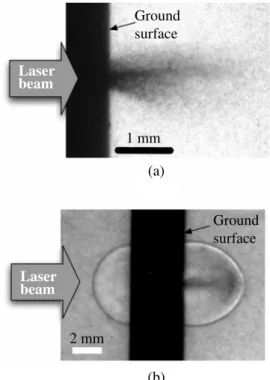
Figure 2 shows typical shadowgraph pictures for ablation in air and in vacuum. Glass plate is seen as a black layer in the pictures in Fig. 2. As seen from Fig. 2(a), burst of glass fragments in vacuum can be observed emanated from the laser focused area. Glass particle motion is found to be almost perpendicular to the surface, but the particle spray have slightly diverged. In air, a circular shock wave front precedes the burst of fragments.
Ablation threshold fluence for ground glass surface is much lower than that for flat glass surface. Air shock is produced in both surface of the glass plate when the laser Laser
Lens Lens
Aperture
Aperture
Glass plate Mirror
Digital or high speed camera Flash lamp
Fig. 1 Schematic layout of experimental setup. Focusing lens of pulse laser should be the one made of quartz, and focal length in this case is 200 mm.
Laser beam
Laser beam
Ground surface
Ground surface 1 mm
2 mm
(a)
(b)
Fig. 2 High speed camera record of laser ablation of
ground glass. Laser beam focuses from right side
to the ground left surface. Photo (a) was taken in
vacuum, and photo (b) in air. Delay time of the
laser irradiation for light source for (a) and (b) is
1.0 µs and 2.2 µs, respectively.
fluence at the glass surface is close to the value of 20 J cm
-2. Dark region consists of glass particles, which was evidenced by directly capturing them by PMMA plates ahead of the particle stream. Such experiments were done in the case of vacuum ablation. It is shown that in vacuum glass frag- ments are proved to move with constant velocity just after they leave the surface. On the contrary, motion of glass particles in air is somewhat different. Glass particles are ejected normal to the surface at their production, and grad- ually spread to the mushroom shape to drive a shock wave.
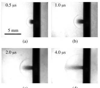
Figure 3 shows the high speed photographs with succes- sive delay time. In this experiments, ground glass plate of
#240 surface roughness was used. Shock wave propaga- tion and glass fragments motion was recorded with time clearly. Since generated particles follows close to the air shock front, maximum particle velocity is roughly 1.5 km s
-1within 1 µs after laser ablation and decelerates to sever- al hundred m s
-1.
We have used diffusion glass plates with different surface roughness. These plates are a kind of optics used for light diffusion. We have used these plates with #240, #400,
#600, #800, #1000 and #1500 roughness levels. It is found that most damaged surface was observed in the case of roughest plate of #240. Even in the case of #1500 plate, surface damage was observed, but the damaged area is found to be limited.
Figure 4 shows the comparison of high speed camera record of the glass ablation of different surface roughness.
Delay time after laser irradiation for all the photographs is set to the same value. Comparing these pictures, one can see that darker burst is generated for rougher glass surface.
Darkness of the particle cloud can be interpreted as larger particles or as a large number of particles.
In case of ground glass ablation, part of the laser energy is converted to high velocity glass particle kinetic energy.
Feasibility of initiating high explosive by this kinetic ener- gy has been examined in this study. A glass plate with one ground surface was used and put on the PETN powder.
Effect of aluminum coating on the ground surface was also studied. We have used a commercially available ground glass plate with a thickness of 2.8 mm in experiments.
Image converter camera (IMACON 790) of the streak mode is used to record the light emission caused by the reaction of PETN.
We have examined the cases of aluminum thickness of 200 nm and 300 nm deposited on ground glass surface. It is found that in all the cases of thicker aluminum layer, deto- nation of PETN powder was recognized. In these cases, mechanism of energy conversion to metal plasma should be similar for both substrate material of PMMA and glass.
3. Results and discussion 3.1 Motion of glass fragments
It is obvious that size of initially ejected glass particles has some definite distribution. Larger and heavier particles may be decelerated less, and they are responsible for the shock drive, while lighter particles are fully decelerated with time. In some photographs at longer delay time, shock wave front is not observed smooth by the reason that some of heavier particle overrides the initially gener- ated shock front. In this case, a small conical shock wave is seen almost attached to these particles.
Similar phenomena have not been observed for ablation of polymer material such as PMMA. Therefore, the phe- nomenon is characteristic of glass material. In case of polymer materials, laser energy absorption may cause the scission of molecular bonds, but not produce macro sized polymer particles. Relatively longer stress relaxation time inherent to polymer materials might explain the difference of ablation behavior from glass.
(c) (d) (c) (d)
Fig. 3 High speed camera record of laser ablation of ground glass plate with #240 surface roughness.
Photos with successive delay time of 0.5, 1.0, 2.0 and 4.0 µs, respectively.
Fig. 4 High speed camera record of laser ablation of optical diffusion plate with different surface roughness,
#240, #400, #800 and #1500. Photos (a) to (d) correspond to the picture of shot using plate of
#240, #400, #800 and #1500 surface roughness,
respectively. Delay time for all the cases is 1.0 µs.
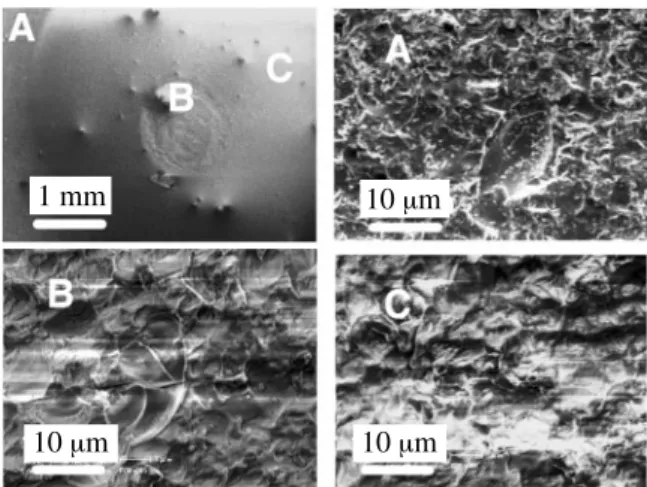
3.2 SEM observation of the ground glass surface Figure 5 shows the typical SEM (Scanning Electron Micrograph) photographs of the ground glass surface after laser ablation. The top left photograph is the overall view of the surface. Laser beam was focused into the central cir- cular region with the diameter of about 1 mm. Point B belongs to this region. One may note that much larger cir- cular area is influenced by laser beam. Since laser beam was focused through the glass material, most of the laser energy was absorbed in a thin surface layer. Surface layer means the thin crack surface structure as well as the ground surface of the specimen. The situation of the pre- sent study of laser absorption process by ns-duration infrared laser is quite different from that for smooth and non-glass material, since in most cases, part of the laser energy is absorbed by the produced plasma plume apart from the ablated surface. Point C represents a typical point in this area. We chose the point A typical of the uninflu- enced region of the surface. Three other photographs in Fig. 5 are the close up of the regions around points A, B and C. We may call three figures also by A, B and C.
It is seen that virgin surface of the ground glass has a lot of sharp edges or peaks and valleys. Many white lines will correspond to these peaks. It also has many cleavage sur- faces. In other words, surface structure of ground glass surface is described not only by the surface form function but also plenty of micro cracks appearing on the surface.
These cracks are expected to be some µm deep into the glass material.
From Figs. 5A and 5B, one can see that laser ablation took these sharp peaks away from the surface. One may also note that apparent cleavage surfaces are recognized, and surface roughness or the characteristic length of the rough surface is longer than that before ablation.
Comparison of figures in Figs. 5A and 5B suggests that intense laser focus gives sharper cleavage of the surface.
In case of ground glass, SEM image suggests large num- ber of cleavage sites on the surface. Laser energy could be absorbed at various surface including cleavage sites pro- ducing small-scale ablation plasma plume at each site and the produced plasma might make the cleavage open to generate a broken pieces of glass. Similar scenario might be expected for various brittle materials with ground sur- faces. Further study is desirable to examine the physical mechanisms of the phenomena.
3.3 Ignition of PETN powder by laser ablation of ground glass
Figure 6 shows examples of streak photographs taken by the image converter camera. The earliest intense flash is the one by emission caused by laser ablation of ground glass surface. Long streak of luminescence after some break indi- cates emission caused by detonation of PETN powder.
Bright region is seen to spread to the direction of camera slit gradually. Since the slope of this bright region corre- sponds to the propagation velocity of detonation, gradual change in slope indicates the acceleration of reaction front approaching the steady state detonation.
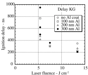
Break in time between laser irradiation and onset of deto- nation emission is called here the ignition delay time.
Value of it for ground glass ignition is shown to be less than 1 µs in case of larger laser fluence. Dependence of the ignition delay time on the laser fluence and aluminum layer thickness was also investigated. The results of a series of experiments are summarized in Fig. 7. Although ignition delay time in the present experiment is not very reproducible, it is obvious that the thicker aluminum layer and higher laser fluence shortens the delay time.
It is shown in this experiment that PETN powder can be ignited by laser ablation of ground glass surface without help of high temperature plasma. In the case of laser abla- tion of ground glass surface, it is suggested that a definite amount of plasma is produced inside the glass crack sur- face which will be responsible for the cleavage and accel- eration of glass fragments. However, luminosity of ablated plasma decreases rapidly with time. This is in sharp con- trast to the long last strong emission from high tempera-
1 mm 10
µm
10
µm 10
µm
Fig. 5 SEM photos of ground glass surface after laser ablation. Commercial ground glass plate was used in the experiments. Laser fluence is 16 J cm
-2. Photo (a) is an overview of the surface area including original surface (mark A), laser focused area (mark B) and laser influenced area (C) in one picture. Photo A, B and C correspond to the closeup SEM picure of three regions.
1 cm
Irradiation Initiation
1
µs
Fig. 6 Streak photograph of light emission associated
with detonation of PETN powder for the case
using only ground glass plate. In this experiment,
commercial ground glass plate was used in the
experiments. Laser fluence is about 20 J cm
-2.
Focused beam diameter of the laser is about 1 mm
almost at the center of 6 mm diameter PETN disc.
ture metal plasma by ablation. By such considerations, the present result of initiation experiments means that the initi- ation is induced simply by the collision of glass particles at the PETN powder grains. It is, therefore, evidenced that kinetic energy of glass particle cloud is large enough to ignite high explosive. Threshold laser fluence for PETN ignition is found to be higher than the value for plasma- assisted initiation. From Fig. 7, it is shown that initiation by glass ablation was observed in the case of laser fluence 11 J cm
-2or more. Among tested, it is found that plasma- assisted method only fails in case with 100 nm Al thick- ness and low fluence 5.4 J cm
-2. This result, however, is not reproducible and the fluence might be near the thresh- old value for this experimental condition.
ing PETN powder.
References
1) M. Nakahara and K. Nagayama, Proc. 21stShock Wave Symp. 1997, (1998) vol. 2, 801.
2) M. Nakahara and K. Nagayama, J. Mat. Proc. Tech., 85 (1999) 20.
3) K. Nagayama, K. Inou, and M. Nakahara, Shock Compression of Condensed Matter-2001, pp. 995-998 (2002).
4) K. Murakami, K. Inou, M. Nakahara, S. Kubota and K.
Nagayama, J. of the Japan Explosives Society, Vol. 63, No.
5, pp. 275-278 November, 2002.
5) K. Nagayama, K. Inou, K. Murakami, S. Kubota and M.
Nakahara, Proc. 29thInt. Pyrotechnics Seminar, pp. 363-368, 2002.
6) S. Kubota, K. Nagayama, H. Shimada and K. Matsui, Shock Compression of Condensed Matter-2001, pp. 285-288 (2002).
7) D. M. Kane , D. R. Halfpenny, J. Appl. Phys., 87 (2000) pp.
4548-4552.
8) Petr Chylek, M. A. Jarzembski, and N. Y. Chou, Appl. Phys.
Lett., 49 (1986) pp. 1475-1477.