メッシュフリー法による応力解析に基づく 三次元異材接合体界面端における特異応力場の強さ
Intensity of stress singularity at the vertex in three-dimensional dissimilar material joints based on stress analysis by mesh free method
◯ 石川 晃広(長岡技科大院) 正 倉橋 貴彦(長岡技科大) 正 古口 日出男(長岡技科大)
Akihiro ISHIKAWA, Graduate School of Nagaoka University of Technology, 1603-1 Kamitomiokamachi, Nagaoka, Niigata Takahiko KURAHASHI, Nagaoka University of Technology, 1603-1 Kamitomiokamachi, Nagaoka, Niigata
Hideo KOGUCHI, Nagaoka University of Technology, 1603-1 Kamitomiokamachi, Nagaoka, Niigata Key Words: Mesh Free Method, 3D Elastic Deformation Problem, Order of Singularity, Intensity of Stress Singularity
1. 緒 言
近年,航空機や自動車,携帯電話等の高性能化,小型化,軽 量化,高強度化が進んでいる.これらの目的を達成するために,
異なる材料を接着・接合した異材接合体が利用されている.しか し,異材接合体に外力が作用すると,接合している材料の弾性 係数やポアソン比等の物性値の違いから,接合・接着界面端の 角部において応力が無限大になる特異応力場が発生する.こ れにより,接合界面角部の接合強度が低下し,界面剥離やき裂 が起こる.異材接合体の界面端では材料の組み合わせや形状 に対して任意の応力特異性が生じ,また複数の特異性が生じる こともあるため,この界面端における応力場を特徴付けるパラメ ータ(特異応力場の強さ)を定量的に把握する必要がある.
本報告では,Al,Fe の接合体を解析対象とし,接合体の幅が 特異応力場の強さに与える影響を調べる.応力解析手法として はメッシュフリー法(1),(2)を適用し,算定された応力分布より特異応 力場の強さを求める.
2. メッシュフリー法
2.1移動最小二乗法による形状関数 図1に示すように3 次元空間に節点のみが存在する場合を考える.任意の節点を 評価点として,その評価点を中心に半径 R(影響半径)の球を描 き,球の内部の領域を Ωk,境界をΓk,評価点から参照点までの 距離dI,I番目の参照点におけるx方向の変位をuIとする.ここ で,I は参照点の番号である.任意の評価点での x 方向の変位 の近似関数uhを式(1)に示す.
uh(x,y,z)=
{ }
g T{ }
a (1)
{ }
gT ={
1 x y z}
,{ }
a T ={
a0 a1 a2 a3}
(2)ここに,{g}は基底ベクトル,{a}は未定係数ベクトルを示す.ここ で,各評価点において uhと uIの差を最も小さくする様な未定係 数ベクトル{a}を決定するため,式(3)に示す評価関数Jを定義す る.
J=
{
!I({ }
g T{ }
a "uI)2}
I=1
#
n (3)Fig. 1 Domain influence
!I= 1"6 dI R
#$% &
'(
2
+8 dI R
#$% &
'(
3
"3 dI R
#$% &
'(
4
, 0)dI)R
0, dI>R
* +,
-, (4)
ここに,ωIは領域Ωk内における重み関数であり,nは領域Ωk内 に存在する参照点の数である.また, 重み関数ωIは式(4)に示す 4 次スプライン関数を用いる.ここで,未定係数ベクトル{a}につ いての J の停留条件により,{a}が決定される.{a}を式(5)に示 す.
{ }
a =[ ]
A!1[ ]
B{ }
u (5)ここで,行列[A],[B]は式(6)に示す行列である.
[ ]
A = (!I{ }
g{ }
g T)I=1
"
n ,[ ]
B =$%!1{ }
g1 # # #!n{ }
gn &' (6)式(5)を式(1)に代入することで式(7)に示す補間関数が得られる.
uh(x,y,z)=
{ }
g T[ ]
A!1[ ]
B{ }
u ={ }
"{ }
u (7)ここに,{Φ}は形状関数である.同様の方法により,y 方向の変 位,z方向の変位に対する形状関数を求める.
2.2剛性方程式 剛性方程式は応力つり合い方程式,ひず み-変位関係式と応力-ひずみ関係式を用いる.図 1 に示す影 響半径R で描いた球(領域 Ωk)で積分を行う.このときの各評価 点に対する領域Ωkの積分は,バックグラウウンドセルを用いたガ ウス・ルジャンドル法により数値積分を行う.式(7)の移動最小二 乗法で求めた形状関数により補間すると式(8)が得られる.
!
[ ]
Kk"
k{ }
U d!="
#k{ }
Ft d# (8)ここに,[Kk]は各評価点の剛性マトリックス,{Ft}の項は表面力を 示す.ここで,各評価点に対して得られた式(8)を全て重ね合わ せることにより式(9)が得られる.
[ ]
K{ }
U ={ }
F (9) ここに,[K]は全体剛性マトリックス,{F}は外力ベクトル,{U}は 各節点の変位ベクトルを示す.形状関数を求める際に移動最小二乗法を用いているため,境 界条件の値を直接的に与えることができない.本報告では境界 条件を満足させるためにペナルティ法を適用する.式(9)を変位 ベクトル{U}について解くことにより,材料の変位量を求めること ができる.式(9)により求めた変位量から,ひずみ・応力値を求め る.
3. 固有値解析
特異性のオーダλを算定するため,本報告ではPageauにより 提案された解析方法を導入する(3).この解析法では式(10)に示 す固有方程式を解くことにより固有値pが求められ,固有値pと 特異性オーダλの間にはλ=1-p となる関係があり,この関係より 特異応力場における特異性オーダλを求める.
-611-
1601
〔No.10-2〕日本機械学会第23回計算力学講演会CD-ROM論文集 〔2010-9.23〜25・北見市〕
(
p2[ ]
C +p D[ ]
+[ ]
E) { }
q =0 (10)ここに,[C],[D]及び[E]は有限要素法により導かれた係数行列で あり,{q}は変位ベクトルである.
4. 数値解析例
4.1 解析モデルおよび解析条件 本報告では,下の材料 をAl,上の材料をFeとして接合した二相弾性体を解析モデルと し,モデルの寸法および形状は図2に示す通りである.解析では,
幅bを0.25~1.0mmまで,7種類(b=0.1,0.25,0.5,0.75,1.0,1.5, 2.0mm)調 整 し , 検 討 を 行 っ た . 外 力 と し ては ,Fe の 上 面 に
W=10MPa の引張応力を与え,異材接合体の応力場を求める.
接合界面角部を原点とし,図2に示す様にφ,θをとり,球座標系 を用いる.対称性を考慮した1/8モデルとして解析を行うため,材 料の右側面をx方向に,後面をy方向に,Alの下面をz方向に 固定する.解析に用いた物性値を表1に示す.本報告において,
影響半径Rは0.15mmとする.また,ペナルティ数αは1.0 1030 とする.
4.2解析結果および考察 図3に各幅bについて接合界 面端角部 の特異応力場 からの距離 r に対する φ=45deg,θ=
90degの応力σθθの分布を示す.また,図4は図3を両対数グラ
フにより表示した応力分布である.図 3,4 より,接合界面端角部 に近づくに伴い,応力σθθが増大していることがわかる.また,幅 bが小さくなるに伴い,応力σθθが減少していることがわかる. 次 に,図4の応力分布を式(11)の特異応力場の式により近似して,
特異応力場の強さを求める.
!ij=K1ijr"#vertex +K2ij (11) ここで,Kkijは特異応力場の強さ,rは接合界面角部からの距離,
λvertexは接合界面端角部での特異性のオーダを表している.固
有値解析より得られた固有値p=0.879である.このことから,固有 値pが1に近いため,AlとFeの接合体は界面端の角部におい て応力特異性が発生し難い材料であることがわかる.特異性オ ーダλと固有値の関係からλ=1-p と表せるため,特異性のオーダ λは0.121となる.
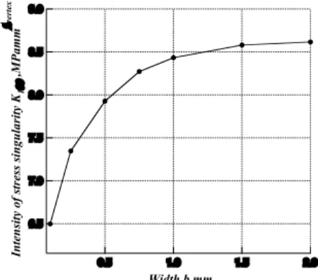
ここで,図4の各応力分布に対して応力特異場の強さK1θθを計 算し,各幅bに対する応力特異場の強さK1θθについて整理した グラフを図5に示す.結果より,幅bが小さくするに伴い,K1θθも 小さくなることがわかる.また,幅bを大きくした場合,特異応力場 の強さK1θθはある一定値に収束する傾向にある.
5. 結 論
メッシュフリー法を用いて,異材接合体に対する応力解析を行 い, 特異応力場の強さK1θθを得ることができた.幅bを小さくす るに伴い,特異応力場の強さ K1θθも小さくなる傾向があることが わかった.また,幅 b を大きくした場合,特異応力場の強さ K1θθ はある一定値に収束する傾向にあることがわかった.
Fig. 2 Computational model
参考文献
(1) Belytschko, T., Lu. Y. Y. and Gu, L., Element-Free Galerkin Method, Int. J. Number. Methods Eng., 37(1994), 229-256.
(2) 鯉沼 吉明,冨岡 昇,岡部 顕史,メッシュレス法による異 材接着突合せ継手の応力解析,年次大会,2001,pp.57-58 (3)Pageau, S. S. and Bigger, Jr. S. B., Finite Element Evaluation of Free-Edge Singular Stress Fields in Anisotropic Material, Int. J. Number. Methods Eng., 38(1995), 2225-2239.
Table 1 Material properties
Materials Al Fe
Young’s modulus E[Pa] 2.86 166
Poisson’s ratio ν 0.38 0.26
12
11
10
9
8
Stress !"",MPa
1.4 1.2 1.0 0.8 0.6 0.4 0.2 0.0
Distance from origin r , mm
Al-Fe interface
(#=45, "=90 deg) b=2.0mm b=1.5 b=1.0 b=0.75 b=0.5 b=0.25 b=0.1
Fig. 3 Distribution of stress σθθ, against distance from origin r on Al-Fe interface
8 9 10
Stress !"",MPa
7 8 9
0.1 2 3 4 5 6 7 8 91
Distance from origin r , mm
Al-Fe interface
(#=45, "=90 deg) b=2.0mm b=1.5 b=1.0 b=0.75 b=0.5 b=0.25 b=0.1 Fitting curve
Fig. 4 Distribution of stress σθθ, against distance from origin r on Al-Fe interface
9.0
8.5
8.0
7.5
7.0
6.5
Intensity of stress singularity K1!! ,MPamm"vertex
2.0 1.5 1.0 0.5
Width b mm
Fig. 5 Intensity of stress singularity K1θθ, against width b
-612-