With Unit Cell Sorting Based on Magic Square
Masashi Higashino
Shaiful Nizam Mohyar, Haruo Kobayashi Division of Electronics and Informatics
Gunma University, Japan
Universiti Malaysia Perlis, Malaysia
26 April 2016
Research Objective
Current Steering DAC
What is Magic Square ?
Proposed Algorithm
Simulation Results
Conclusion
Research Objective
Current Steering DAC
What is Magic Square ?
Proposed Algorithm
Simulation Results
Conclusion
Unary DAC linearity improvement - Unit cell sorting algorithm
- Based on Magic Square - Digital method
No analog part modification
Demand for DAC in communication systems - High linearity
- High spurious free dynamic range (SFDR) Research Background
Our Approach
New!!!
Research Objective
Current Steering DAC
What is Magic Square ?
Proposed Algorithm
Simulation Results
Conclusion
Unary Current-Steering DAC
• Identical current sources
• Small glitch
• Inherent monotonicity
• High speed
• Large circuits - Decoder
- Many switches and current sources
+
Vout
-
Digital input = 1 , 1 current source.
Current cell output
+
Vout
-
Digital input = 1 , 1 current source.
“ = 2 , 2 current sources.
+
Vout
-
Digital input = 1 , 1 current source.
“ = 2 , 2 current sources.
“ = 7 , 7 current sources.
DAC is perfectly linear
+
Vout
-
①Binary-code
②Thermometer-code
Example 1
Digital binary input (0010)
Thermometer code (0000 0000 0000 0011) 2 current cells turn on.
Digital binary input (0011)
Thermometer code (0000 0000 0000 0111) 3 current cells turn on.
Example 2
Research Objective
Current Steering DAC
What is Magic Square ?
Proposed Algorithm
Simulation Results
Conclusion
4 9 2 3 5 7 8 1 6
魔方陣
Classical mathematics
Origin from Chinese academia
“Constant sum” characteristics
Varieties of magic squares
4 9 2 3 5 7 8 1 6
3x3 魔方陣
• Constant Sum
- Row, column, diagonal
魔方陣 is Good balance
16 3 2 13 5 10 11 8 9 6 7 12 4 15 14 1
16+3+2+13=34
16+10+7+1=34 16+5+9+4=34
Research Objective
Current Steering DAC
What is Magic Square ?
Proposed Algorithm
Simulation Results
Conclusion
In practice, current sources have mismatches.
DAC becomes non-linear.
+
Vout
-
1 15 14 4 12 6 7 9 8 10 11 5 13 3 2 16
Semiconductor devices have
random and systematic mismatches
Changing the switching order
Cancellation of mismatch effects
We propose magic square algorithm
Din Error
magic square algorithm normal algorithm
Unit current source selection-order change algorithm - Mismatch effect cancellation
1. Measure the order of unit current cells
2. Align them virtually in magic square
3. Select current cells
1 15 14 4 12 6 7 9 8 10 11 5 13 3 2 16
+
Vout
-
I1 I2 I3 I4 I5 I6 I7 I8 I9 I10 I11 I12 I13 I14 I15 I16
Calibration Algorithm
Input Test Code & Measurement
Unary-DAC
Measurement Circuit CPU
CPU => input test code to unary-DAC cells
Measurement circuit => order of current source values Input test code
Order of current source values 1st Step
Current comparator
Measure Order of Current Cells
Current cell
4-bit case
Measure the order of current cell values by a current comparator.
Not need accurate value measurement.
average
1st Step
I1 I2 I3 I4 I5 I6 I7 I8 I9 I10 I11 I12 I13 I14 I15 I16
Unit Current Source Sorting
Unary-DAC
Sort and store the measured order of the unit current cell values into memory.
2nd step
Memory
Measurement Circuit
Sorted Current Source
Sort current source cells ascendingly.
Store their information of cells number and value into memory.
Unit Current Source Sorting
average
2nd step
Current Source Sorting Based on Magic Square
Unary-DAC CPU
Re-sort of current source values based on magic square 3rd step
Memory
Current Source Sorting Based on Magic Square (1)
Re-sorted of current source values based on magic square
Store its info in decoder look-up table
1 15 14 4 12 6 7 9 8 10 11 5 13 3 2 16
switching order 3rd step
I1 I2 I3 I4 I5 I6 I7 I8 I9 I10 I11 I12 I13 I14 I15 I16
Digital binary input (0001) 1 current cells turn on
Current Source Sorting Based on Magic Square (2)
I1 I2 I3 I4 I5 I6 I7 I8 I9 I10 I11 I12 I13 I14 I15 I16
Digital binary input (0010) 2 current cells turn on
Current Source Sorting Based on Magic Square (3)
I1 I2 I3 I4 I5 I6 I7 I8 I9 I10 I11 I12 I13 I14 I15 I16
Digital binary input (0011) 3 current cells turn on
Current Source Sorting Based on Magic Square (4)
I1 I2 I3 I4 I5 I6 I7 I8 I9 I10 I11 I12 I13 I14 I15 I16
Digital binary input (0100) 4 current cells turn on
Current Source Sorting Based on Magic Square (5)
I1 I2 I3 I4 I5 I6 I7 I8 I9 I10 I11 I12 I13 I14 I15 I16
LUT-Magic Square Decoder
Unary-DAC
Programmable Decoder
Digital input Analog output
Store switching sequence based on magic square into programmable decoder.
Final Step
High-linearity
Programmable Decoder CPU
LUT-Magic Square Decoder
Magic square switching
sequence is stored in decoder
Cancel mismatch effect
1 15 14 4 12 6 7 9 8 10 11 5 13 3 2 16
average
I1 I2 I3 I4 I5 I6 I7 I8 I9 I10 I11 I12 I13 I14 I15 I16
Research Objective
Current Steering DAC
What is Magic Square ?
Proposed Algorithm
Simulation Results
Conclusion
Simulation Conditions
MATLAB simulation
8-bit unary DAC
- Static performance (INL, DNL) - Dynamic performance (SFDR)
Compared two methods
- Conventional thermometer-code decoder usage - Proposed magic-square-based algorithm
Mismatch of current sources
- Current sources have average of value 1.0
- Random number between -1 < mismatch < +1 (uniform distribution)
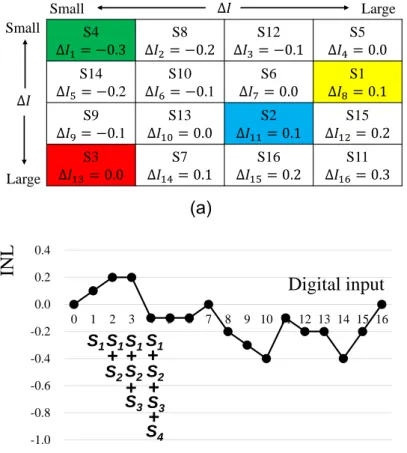
- Static Performance INL -
Integral Non-Linearity (INL)
5.7 LSB improvement by the magic square algorithm
0.0 LSB at the center of the input range Din
- Static Performance DNL -
Differential Non-Linearity (DNL)
Small at the center of the input range Din
- Dynamic Performance SFDR -
SFDR improvement by 7 dB
Conventional method Proposed method
Research Objective
Current Steering DAC
What is Magic Square ?
Proposed Algorithm
Simulation Results
Conclusion
Unary DAC linearity improvement
- Cancel unit current cell mismatch effects - Unit current cell selection algorithm
Digital method
- Based on magic square
- Measurement of the order of current cell values
MATLAB simulation
- INL , DNL improvement
at the center of the input range.
- SFDR improvement
温故知新
Classical mathematics can contribute modern technology.
Kobayashi Lab.
Gunma University
DAC Linearity Improvement With Layout Technique
Using Magic and Latin Squares
Dan Yao, Yifei Sun, M. Higashino, S. N. Mohyar T. Yanagida T. Arafune, N. Tsukiji, H. Kobayashi
Gunma University
Research Objective
Segment Type DA Converter
Characteristic of Variation in Circuit Element
Proposed Layout Method - Magic Square
- Latin Square
Conclusion
2017/11/5
Research Objective
Segment Type DA Converter
Characteristic of Variation in Circuit Element
Proposed Method
- Magic Square - Latin Square
Conclusion
2017/11/5
Objective
Development of
a highly linear digital-to-analog converter (DAC)
Our Approach
DAC layout technique
to cancel systematic mismatch effects among unit current cells.
-Layout based on Magic and Latin Squares
2017/11/5
Analog
New!!
DAC
Digital
Research Objective
Segment Type DA Converter
Characteristic of Variation in Circuit Element
Proposed Method
- Magic Square - Latin Square
Conclusion
2017/11/5
2017/11/5
Segmented DAC
Binary (Lower bits) - Small circuit
- Large glitch
- Large mismatch effect &
Large nonlinearity
Unary (Upper bits) - Large circuit
- Small glitch
- Small mismatch effect &
modest linearity
Focus !!
8I 8I 8I
𝑉𝑜𝑢𝑡 = 4𝐼𝑅𝐹
ex.1
In case digital input =4
𝑉𝑜𝑢𝑡 = 12𝐼𝑅𝐹
(0000100) (0001100)
ex.2
In case digital input =12
2017/11/5
Lower bit: binary
Upper bit: unary Lower bit: binary
Upper bit: unary
2017/11/5
• Identical current sources
• Small glitch
• Inherent monotonicity
• Large circuits - Decoder
- Many switches and current sources
𝑉𝑜𝑢𝑡 = 12𝐼𝑅𝐹 (0001100)
Unit current cell (unary)
S1 S2 S3 S4 S5 S6 S7 S8 S9 S10 S11 S12 S13 S14 S15 S16
7bit DA Converter
2017/11/5
Lower bit: binary
Upper bit: unary
2017/11/5
1 15 14 4 12 6 7 9 8 10 11 5 13 3 2 16
Semiconductor devices have systematic mismatches
Changing the unit cell layout order
Cancellation of systematic mismatch effects
We propose magic and Latin squares algorithms
Din Error
magic square algorithm
regular algorithm Linear error Quadratic error
Research Objective
Segment Type DA Converter
Characteristic of Variation in Circuit Element
Proposed Method
- Magic Square - Latin Square
Conclusion
2017/11/5
Systematic variations
Voltage drop
Thickness of oxide film
Doping
Mechanical stress
Temperature distribution
In wafer plane
Quadratic error
Linear error
Joint Error (Sum of both)
2017/11/5
𝜀𝑞 𝑥, 𝑦 = 𝑔𝑞 ∗ 𝑥2 + 𝑦2 − 𝑎0
𝜀𝑙 𝑥, 𝑦 = 𝑔𝑙 ∗ cos 𝜃 ∗ 𝑥 + 𝑔𝑙 ∗ sin 𝜃 ∗ 𝑦 Linear Error
𝜀𝑗 𝑥, 𝑦 = 𝜀𝑙 𝑥, 𝑦 + 𝜀𝑞 𝑥, 𝑦 Quadratic Error
Joint Errors
Research Objective
Segment Type DA Converter
Characteristic of Variation in Circuit Element
Proposed Method - Magic Square - Latin Square
Conclusion
2017/11/5
2017/11/5
• Classical mathematics
• Origin from Chinese academia
• “Constant sum” characteristics
• Varieties of magic squares
2 9 4
7 5 3
6 1 8
3 × 3 Magic Square
2017/11/5
Constant Sum
Row, Column, Diagonal
Magic Square is good balance
16 3 2 13 5 10 11 8 9 6 7 12 4 15 14 1
16+3+2+13=34
16+10+7+1=34 16+5+9+4=34
Concentric Magic Square
Even if one side is removed from the outside, it does not lose compatibility
Numbers are
in symmetrical positions
Effective for cancellation of systematic variation effects
2017/11/5
expected
Concentric Magic Square
8-bit unit current source cells
by combining 8-th order squares
A1 B1 B2 A2
A: Magic square
B: 45 ° counterclockwise rotation
59 5 4 62 63 1 8 58 9 18 17 49 50 42 19 56 55 20 28 33 29 40 45 10 54 44 38 31 35 26 21 11 12 43 39 30 34 27 22 53 13 24 25 36 32 37 41 52 51 46 48 16 15 23 47 14 7 60 61 3 2 64 57 6
2017/11/5
59 5 4 62 63 1 8 58 58 56 10 11 53 52 14 6 9 18 17 49 50 42 19 56 8 19 45 21 22 41 47 57 55 20 28 33 29 40 45 10 1 42 40 26 27 37 23 64 54 44 38 31 35 26 21 11 63 50 29 35 34 32 15 2 12 43 39 30 34 27 22 53 62 49 33 31 30 36 16 3 13 24 25 36 32 37 41 52 4 17 28 38 39 25 48 61 51 46 48 16 15 23 47 14 5 18 20 44 43 24 46 60 7 60 61 3 2 64 57 6 59 9 55 54 12 13 51 7 58 56 10 11 53 52 14 6 59 5 4 62 63 1 8 58
8 19 45 21 22 41 47 57 9 18 17 49 50 42 19 56 1 42 40 26 27 37 23 64 55 20 28 33 29 40 45 10 63 50 29 35 34 32 15 2 54 44 38 31 35 26 21 11 62 49 33 31 30 36 16 3 12 43 39 30 34 27 22 53 4 17 28 38 39 25 48 61 13 24 25 36 32 37 41 52 5 18 20 44 43 24 46 60 51 46 48 16 15 23 47 14 59 9 55 54 12 13 51 7 7 60 61 3 2 64 57 6
Concentric Magic Square
A1 B1 B2 A2
algorithm
2017/11/5
A1 B1 B2 A2
59 5 4 62 63 1 8 58 58 56 10 11 53 52 14 6 9 18 17 49 50 42 19 56 8 19 45 21 22 41 47 57 55 20 28 33 29 40 45 10 1 42 40 26 27 37 23 64 54 44 38 31 35 26 21 11 63 50 29 35 34 32 15 2 12 43 39 30 34 27 22 53 62 49 33 31 30 36 16 3 13 24 25 36 32 37 41 52 4 17 28 38 39 25 48 61 51 46 48 16 15 23 47 14 5 18 20 44 43 24 46 60 7 60 61 3 2 64 57 6 59 9 55 54 12 13 51 7 58 56 10 11 53 52 14 6 59 5 4 62 63 1 8 58
8 19 45 21 22 41 47 57 9 18 17 49 50 42 19 56 1 42 40 26 27 37 23 64 55 20 28 33 29 40 45 10 63 50 29 35 34 32 15 2 54 44 38 31 35 26 21 11 62 49 33 31 30 36 16 3 12 43 39 30 34 27 22 53 4 17 28 38 39 25 48 61 13 24 25 36 32 37 41 52 5 18 20 44 43 24 46 60 51 46 48 16 15 23 47 14 59 9 55 54 12 13 51 7 7 60 61 3 2 64 57 6
Concentric Magic Square
Unit cell
selection algorithm
2017/11/5
A1 B1 B2 A2
59 5 4 62 63 1 8 58 58 56 10 11 53 52 14 6 9 18 17 49 50 42 19 56 8 19 45 21 22 41 47 57 55 20 28 33 29 40 45 10 1 42 40 26 27 37 23 64 54 44 38 31 35 26 21 11 63 50 29 35 34 32 15 2 12 43 39 30 34 27 22 53 62 49 33 31 30 36 16 3 13 24 25 36 32 37 41 52 4 17 28 38 39 25 48 61 51 46 48 16 15 23 47 14 5 18 20 44 43 24 46 60 7 60 61 3 2 64 57 6 59 9 55 54 12 13 51 7 58 56 10 11 53 52 14 6 59 5 4 62 63 1 8 58
8 19 45 21 22 41 47 57 9 18 17 49 50 42 19 56 1 42 40 26 27 37 23 64 55 20 28 33 29 40 45 10 63 50 29 35 34 32 15 2 54 44 38 31 35 26 21 11 62 49 33 31 30 36 16 3 12 43 39 30 34 27 22 53 4 17 28 38 39 25 48 61 13 24 25 36 32 37 41 52 5 18 20 44 43 24 46 60 51 46 48 16 15 23 47 14 59 9 55 54 12 13 51 7 7 60 61 3 2 64 57 6
Concentric Magic Square
2017/11/5
Unit cell
selection algorithm
1. 1 in A1 2. 1 in A2 3. 1 in B1 4. 1 in B2 5. 2 in A1
⋮
1023. 256 in B1 1024. 256 in B2
Represent pseudo-random switching while taking care of center and corners
A1 B1 B2 A2
Concentric Magic Square
algorithm
2017/11/5
2017/11/5
Concentric Magic Square
Linear Error (Current Cell Systematic Mismatch)
𝜀𝑙 𝑥, 𝑦 = 𝑔𝑙 ∗ cos 𝜃 ∗ 𝑥 + 𝑔𝑙 ∗ sin 𝜃 ∗ 𝑦 𝜃 = 30°
𝑔𝑙 = 1
2017/11/5
Concentric Magic Square
Quadratic Error (Current Cell Systematic Mismatch) 𝑔𝑞 = 1, 𝑎0 = 0
𝜀𝑞 𝑥, 𝑦 = 𝑔𝑞 ∗ 𝑥2 + 𝑦2 − 𝑎0
2017/11/5
Joint Error
Linear > Quadratic case
Concentric Magic Square
The size of the variation
2017/11/5
Joint Error
Linear > Quadratic case
Concentric Magic Square
The size of the variation
Magic square is better
2017/11/5
Joint Error
Concentric Magic Square
Linear < Quadratic case
The size of the variation
2017/11/5
Joint Error
Concentric Magic Square
Linear < Quadratic case
The size of the variation
Random Walk is better Is the magic square suitable for temporary variation?
Research Objective
Segment Type DA Converter
Characteristic of Variation in Circuit Element
Proposed Method - Magic Square - Latin Square
Conclusion
2017/11/5
2017/11/5
Leonhard Euler(1707-1783) Swiss mathematician, physicist
𝑛 × 𝑛 array filled with 𝑛 different symbols
Each symbols occurring exactly once in each row and column
Example:
A B C
C A B
B C A
3 × 3 Latin square
1 2 3 4
3 4 1 2
4 3 2 1
2 1 4 3
4 × 4 Latin square
Considering a “complete Latin square”; for even n,
put the numbers I through n in the first row in the following order: 1, 2, n, 3, n-1,…., n/2+2, n/2+1.
2017/11/5
2017/11/5
8-bit unary DAC
- Static performance (INL)
- Dynamic performance (SFDR)
Compared three methods
- Complete Latin Square - Common Centroid
- Unary Layout
Mismatch of current sources
- Current sources have average value of 1.0
- Random number between -1 < mismatch < +1 (uniform distribution)
1 3 6 7 15 9 12 13 4 5 8 2 10 11 14 16
3 2 4 5 8 16 10 11 6 7 1 9 12 13 15 14
6 4 2 3 5 7 16 9 8 1 10 12 14 15 13 11
7 5 3 1 4 6 8 15 2 9 11 13 16 14 12 10
15 8 5 4 1 3 6 7 10 11 14 16 13 12 9 2
9 16 7 6 3 2 4 5 12 13 15 14 11 10 1 8
12 10 16 8 6 4 2 3 14 15 13 11 9 1 7 5
13 11 9 15 7 5 3 1 16 14 12 10 2 8 6 4
4 6 8 2 10 12 14 16 1 3 5 7 15 9 11 13
5 7 1 9 11 13 15 14 3 2 4 6 8 16 10 12
8 1 10 11 14 15 13 12 5 4 2 3 6 7 16 9
2 9 12 13 16 14 11 10 7 6 3 1 4 5 8 15
10 12 14 16 13 11 9 2 15 8 6 4 1 3 5 7
11 13 15 14 12 10 1 8 9 16 7 5 3 2 4 6
14 15 13 12 9 1 7 6 11 10 16 8 5 4 2 3
16 14 11 10 2 8 5 4 13 12 9 15 7 6 3 1
2017/11/5
Standard Latin square layout algorithm
Quadratic Error Linear Error
2017/11/5
Regular layout
Common centroid
Latin square
SFDR improved !
Research Objective
Segment Type DA Converter
Characteristic of Variation in Circuit Element
Proposed Method
- Magic Square - Latin Square
Conclusion
2017/11/5
2017/11/5
Unary DAC linearity improvement
- Unit current cell systematic mismatch effects cancellation
- Unit current cell layout algorithm
based on magic square and Latin square
Simulation validation - INL improvement - SFDR improvement
2017/11/5
温故知新
Classical mathematics can contribute modern technology.
謝謝
22
J. Tech. Soc. Sci., Vol.4, No.1, 2020
Based on Magic Square
Masashi Higashino 1, a, Shaiful Nizam Bin Mohyar 2, b, Yao Dan 1, c Yifei Sun 1 , d, Anna Kuwana 1 , e, Haruo Kobayashi 1, f
1Division of Electronics and Informatics, Faculty of Science and Technology Gunma University, Kiryu 376-8515 Japan
2 School of Microelectronic Eng., University Malaysia Perlis, Pauh Putra Campus, Arau, Perlis, 02600 Malaysia
a< [email protected]>, b< [email protected]>, c<[email protected]>
d<[email protected]>, e<[email protected]>, f<[email protected]>
Keywords: digital-to-analog converter, magic square, linearity, layout, calibration algorithm
Abstract. This paper describes techniques to improve the linearity of the unary digital-to-analog converter (DAC). We have developed two techniques based on magic square properties; a layout technique and a switching algorithm of unit current (capacitor) cells to canceling their systematic and/or random mismatch effects. Simulation results and discussions are provided for DAC linearity comparison in cases that the proposed magic square and conventional algorithms are used. We show that there are possibilities to obtain better unary DAC linearity by employing magic square algorithms, depending on mismatch characteristics, because the magic square has well-balanced 2-dimensional characteristics. There are rich mathematical research assets for magic squares and their usage would lead to linearity improvement algorithms for the DAC in nano-CMOS era.
1. Introduction
Recently, electronic devices such as mobile phones, wireless modems and tablet terminators demand for small-sized, high-speed and high-linearity digital-to-analog-converters (DACs).
Especially, in fields of wireless communication, the accuracy (linearity) of the DAC is very important to ensure the avoidance from the interference leakage during transmission. Semiconductor devices on silicon wafer suffer from random and systematic mismatches regarding to characteristics of MOSFETs, resistors, and capacitors, which cause input and output relationships of the DAC to be non-linear.
In this paper, we have developed two techniques for the unary DAC linearity improvement by using
“constant sum” characteristic of the magic square. One is a layout algorithm, while the other is a sorting algorithm or a switching selection algorithm of the unit current (capacitor) cells.
As the first method, we propose a magic square layout technique to improve the linearity of the unary DAC to cancel systematic mismatch effects among unit current (or capacitor) cells. (Precisely speaking, this technique is a unit cell selection algorithm based on magic square, considering the unit cell array layout. For simplicity, we call this technique as a layout technique based on magic square.) The magic square is a kind of a classical mathematics and has well-balanced characteristics [1].
Simulation results and discussions are shown for comparison between magic square and regular layout techniques.
As the second method, we propose a unit cell sorting algorithm based on magic square properties for improvement of the DAC linearity (we consider here both integral nonlinearity (INL) and differential nonlinearity (DNL)). Since not only the static performance but also the dynamic
23
J. Tech. Soc. Sci., Vol.4, No.1, 2020 signal. However in actual chip implementation, the DAC linearity is degraded due to unit current source mismatches. Hence, we propose here a unit cell sorting algorithm based on magic square calibration to cancel the random and systematic mismatch effects. We show its simulation results to demonstrate its effectiveness, and provide some considerations.
Notice that most of high-resolution DACs consist of unary configuration for higher bits and binary one for lower bits due to good balance of performance, chip area and power. The unary configuration part for higher bits is important for the overall DAC linearity [3]. Then we focus on the unary part here.
2. Problem Formulation 2.1 Unary-DAC Architecture
A unary DAC employs a unary weighted (identical) current source structure (Fig.1). The unary weighted structure requires 2N-1 unit current sources for N-bit resolution where all current source weights are identical as expressed in eq. (1):
𝐼1 = 𝐼2 = ⋯ . = 𝐼14 = 𝐼15 (1)
For the operation of the unary weighted structure, a binary-to-thermometer code decoder is required.
The unary DAC has characteristics of small glitch and inherent monotonicity, even though this architecture suffers from large decoder circuits and many switches which increase silicon chip area.
2.2 DAC Nonlinearity
In practical CMOS technologies, the current source mismatches are influenced by their threshold voltage (Vth) mismatch and/or by the slope (β) mismatch (Fig.2) [2]. The nominal drain current (Id) in saturation region is given by:
| | | |2
2 gs th
d V V
I
Also drain current mismatch is given by:
WL t Av V V I
I th ox
th gs d
d
|
|
|
| 2
Here Id is its drain current, ΔId is its mismatch (standard deviation), β is its current slope, Vgs is its gate-source voltage, Vth is its gate-source voltage, W is its channel width, L is its channel length, tox
is its gate oxide thickness, Avth is a constant (extracted parameter value). We see that current mismatches are dependent on their device sizes (W, L). Note that here, we are considering to reduce the DAC nonlinearity effects of the current mismatches due to small device size WL .
Fig.1. Unary digital-to-analog converter.
Vdd
・・・
+ VOUT
- I1
S1
I2 S2
I15 S15
I16 S16 IOUT R
24
J. Tech. Soc. Sci., Vol.4, No.1, 2020 Fig. 2. ΔI1, ΔI2 are current mismatches for I1, I2, respectively.
When we consider the current mismatches in Fig. 2, eq. (1) is changed to as follows:
𝐼1 = 𝐼 + 𝛥𝐼1, 𝐼2 = 𝐼 + 𝛥𝐼2, … , 𝐼15= 𝐼 + 𝛥𝐼15 If we define I as follows:
𝐼 = (𝐼1+ 𝐼2 + ⋯ + 𝐼14+ 𝐼15)/15 then we have the following:
𝛥𝐼1+ 𝛥𝐼2+ ⋯ + 𝛥𝐼14+ 𝛥𝐼15 = 0.
2.3 Magic Square
Characteristic of the magic square is a constant sum of each row, column and diagonal [1]. We consider that this characteristic is good balance for unit cell arrange sorting for DAC linearity improvement by cancelling random and systematic mismatch effects among unit cells. We propose unary DAC linearity improvement algorithms by using magic square.
Now we explain about the magic square, which is a square matrix where different integers are arranged to begin with 1 into n×n. Furthermore, each row, column, and diagonal components have the same sum. Generally, we call the n×n magic square matrix as an n class magic square. Constant sum of the n class magic square is expressed as follows:
2
21
nn
S
We show a 4×4 magic square in Fig.3, it can be confirmed that the sum of the elements of each row, column and diagonal components are all equal.
Fig.3. Constant sum characteristics of magic square.
I
W/L ⋯
I1 I2 I16
I1 =I+ΔI1 I2 =I+ΔI2 I16 =I+ΔI16
⋯
4 9 7 14
16 5 11 2 13 8 10 3 1 12 6 15
4 9 7 14
16 5 11 2 13 8 10 3 1 12 6 15
25
J. Tech. Soc. Sci., Vol.4, No.1, 2020 depend on the placement of the circuit element. Ideally, the input and output signals of the DAC should be linear, however due to these variation effects, it becomes nonlinear. The causes of each variation are as follows [2-11].
1) Systematic variation
· Voltage drop on wiring
· Temperature distribution
· CMOS manufacturing process a) Doping distribution
b) Changes in threshold voltage due to thickness of oxide film
· Accuracy in wafer plane
· Mechanical stress 2) Random variation
·Device mismatch
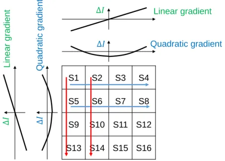
The systematic variation has linear and quadratic gradient variations regarding to the circuit element placement. These are added up and affect circuit operation.
1) Linear gradient variation
· Voltage drop on wiring
· CMOS manufacturing process 2) Quadratic gradient variation
·Temperature distribution
· Accuracy in wafer plane
· Mechanical stress
The above variations largely affect the DAC linearity. The variations 𝜀(𝑥, 𝑦) are modeled with linear and quadratic variations as well as their combination; they are shown by the following:
1) Linear error: 𝜀𝑙(𝑥, 𝑦) = 𝑔𝑙∗ cos 𝜃 ∗ 𝑥 + 𝑔𝑙∗ sin 𝜃 ∗ 𝑦
𝜃: Angle of inclination, 𝑔𝑙: Magnitude of the slope 2) Quadratic error: 𝜀𝑞(𝑥, 𝑦) = 𝑔𝑞∗ (𝑥2+ 𝑦2) − 𝑎0
𝑔𝑞: Variable quantity, 𝑎0: Position
3) Linear and quadratic joint errors: 𝜀𝑗(𝑥, 𝑦) = 𝜀𝑙(𝑥, 𝑦) + 𝜀𝑞(𝑥, 𝑦)
Here, (x, y) is the coordinates of the position on the chip. Notice that (0, 0) is not necessarily at the center of the chip; it depends on the modeling of the gradient variation.
3. First Technique
3.1 Unit Cell Layout Based on Magic Square
The influence of the systematic variation on the linearity of the DAC can be mitigated by the layout technique for the unit cells (Figs. 4, 5). In the case of the unary DAC, the variation effects may be reduced by a random walk method, and then it improves the linearity (Fig. 6) [3, 4].
A magic square has a property that the sums of each row / column / diagonal elements are all equal.
Hence we consider that this property balances the unit cell array of the unary type DAC, and we have investigated the layout of the unit cells to reduce the systematic variation effects to improve the DAC linearity.