INVITED PAPER
Special Section on Electronic DisplaysMultilayer Wavelength-Selective Reflector Films for LCD Applications
Saswatee BANERJEE†a),Nonmember
SUMMARY We designed multilayer wavelength-selective reflector films by stacking thin-films of transparent polymer. The optimum struc- ture of the multilayer is determined using a combination of characteristic matrix method and a version of genetic algorithm. Such multilayer films can be used in LCD devices to enhance the color saturation of the display.
key words: optical design, multilayer, color enhancement film, LCD, ge- netic algorithm
1. Introduction
Multilayer plastic films capable of showing iridescent colors were developed for display purposes [1]. Recently, multi- layered reflector films are designed and developed for broad wavelength band, broad angular range applications [2]–[4].
Such films are commonly used in liquid crystal displays (LCDs) to increase the overall brightness without affecting the color saturation of the LCD devices.
Typically, such multilayer films are composed of hun- dreds of coextruded thin layers of polymer. Thickness of any individual layer is less than the wavelength (λ) of vis- ible light, typically less than 200 nm. The multilayer is a periodic or quasi-periodic structure that is formed by re- peating one basic unit containing two layers of two different materials (say, A and B). Layers A and B are chosen from transparent, non-absorbing polymers. In case of polarizing reflectors, one of the layers (say, A) is optically isotropic while the other layer is uniaxially birefringent. Such films are highly reflective in one polarization mode and are highly transmissive in the orthogonal polarization mode.
Many methods are available for the design of thin film multilayers [5]. In recent times, the automatic design meth- ods based on local and global optimization techniques at- tracted much attention. Various authors have used genetic algorithm (GA), a global optimization technique, to design multilayers possessing uniformly high reflectivity over a broad range of angles [4], antireflection properties for in- frared wavelengths [6], high reflectivity over a narrow band of wavelengths [6], [7], and high reflectivity in extreme ul- traviolet light [8].
In this paper we discuss the design process of a wavelength-selective multilayer film. The film can also function as a polarizing reflector. Such films might be
Manuscript received March 4, 2013.
Manuscript revised June 7, 2013.
†The author is with the Advanced Materials Research Lab., Sumitomo Chemical Co., Ltd., Tsukuba-shi, 300-3294 Japan.
a) E-mail: [email protected] DOI: 10.1587/transele.E96.C.1373
used in LCDs to enhance the color saturation of the device.
Our computations reveal that the structure of wavelength- selective (WS) reflector film can be simpler than the conven- tional broadband multilayer film. This fact also makes the fabrication of our structures significantly easier and cheaper compared to the existing broadband multilayer films.
A computer program is developed. The program im- plements a combination of a characteristic matrix method and a version of GA and is used to design the wavelength- selective (ws) multilayer film mentioned above. The refrac- tive indices and thicknesses of layers A and B are deter- mined so that the reflectivity spectrum in one polarization mode matches a prespecified target spectrum.
The design method is described in Sect. 2. The re- flectivity spectra of the optimum multilayer structure as ob- tained from the program and the proposed application of the same in LCD devices are described in Sect. 3. A discus- sion of the design process and the optimum solutions are presented in Sect. 4.
2. Design Method
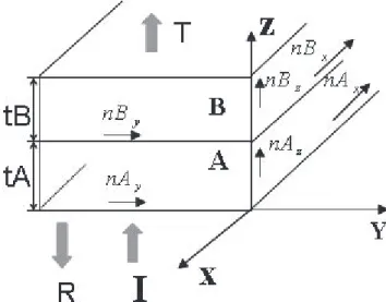
Figure 1 shows the basic unit of the multilayer consisting of two layers A and B. The principal refractive indices of layers A and B arenAx,nAy,nAzandnBx,nBy,nBzrespec- tively. tA andtB are the thicknesses of the layers A and
Fig. 1 Basic structural unit of a multilayer consisting of layers A and B, the directions of incident, reflected and transmitted light are indicated with the letters I, R and T respectively.
Copyright c2013 The Institute of Electronics, Information and Communication Engineers
B respectively. We consider the case of normal incidence where the incident and transmitted light propagate along the z-axis while reflected light propagates along−z-axis.
2.1 Characteristic Matrix
The reflection and transmission properties of a thin-film layer can be computed from a 2×2 matrix known as charac- teristic matrix [9]. The elements of this matrix are obtained by solving the Maxwell’s equations analytically and imple- menting the boundary conditions on the electric and mag- netic fields at any interface between two consecutive layers.
The boundary conditions require that the tangential compo- nents of the electric and magnetic vectors are continuous across the interface. This solution is appropriate when the lengths of the films in directions normal to the plane of in- cidence can be assumed to be infinite.
The characteristic matrix,MABfor the basic unit shown in Fig. 1 is given by [9]
MAB=MAMB (1)
whereMA and MB are the characteristic matrices for lay- ers A and B respectively.MAandMBare determined by the admittancesαA,αBof layers A and B respectively. In trans- verse electric or TE (electric field is normal to the incidence plane, yz) and transverse magnetic or TM (electric field is in the incidence plane, yz) modes, for normal incidence,αA andαBare given by [2]
αAT E=nAx (2)
αBT E=nBx (3)
αAT M=nAy (4)
αBT M=nBy (5)
In Eqs. (2) and (5), the subscripts TE and TM stand for the TE and TM modes respectively. The optical thicknesses ηAandηBof layers A and B are given by
ηAT E=αAT E·tA (6)
ηBT E=αBT E·tB (7)
ηAT M=αAT M·tA (8)
ηBT M=αBT M·tB (9)
The condition for constructive interference for the pair of layers shown in Fig. 1 is given by
ηA+ηB=qλ
2 (10)
whereqis an odd number. If Eq. (10) is satisfied at a wave- lengthλ, corresponding reflectivity reaches a maximum.
For a stack consisting ofNbasic units, the characteris- tic matrixMis given by [9]
M=(MAB)N (11)
Reflectivity of the stack can be computed using the el- ements ofM. If the elements of Marem1,1,m1,2,m2,1 and
m2,2, the reflectivity of the stack is given by R=
(m1,1+m1,2nL)nF−(m2,1+m2,2nL) (m1,1+m1,2nL)nF+(m2,1+m2,2nL)
2
(12) In the abovenFandnLare the refractive indices for the incident and the emergent media respectively.
2.2 Optimization
The problem of design of the multilayer film is formulated as a constrained optimization problem. The performance of a multilayer is estimated in terms of the difference between the reflectivity spectrum of the multilayer and a prespecified target spectrum. A merit functionφis defined to measure this difference.φis given by
φ= 1 Nλ
Nλ
j=1
(Rj−ρj)2 (13)
whereNλis the total number of wavelength sampling points.
Rjis the reflectivity of the multilayer at the wavelength sam- pling point λj. ρj is the target reflectivity atλj. Here, Nλ is 60 (interval =5 nm), in the wavelength range [400 nm, 700 nm].
φis minimized using a GA method. GA is a stochas- tic intelligent search method. The algorithm starts with a population of randomly generated solutions. Each solution represents a multilayer structure. The solutions are updated through a given number of generations by applying various operators that roughly mimic the natural evolution process.
The evolution process is implemented with the help of op- erators, such as, tournament selection, uniform crossover and bit mutation [10]. Apart from the three major opera- tors mentioned above, a measure of genetic diversity is in- troduced to ensure sufficient diversity in the population as it progresses through newer generations. This avoids stagna- tion around a local optimum.
A speciation scheme is incorporated in order to be able to identify a number of local minima as well as the global minimum.
A brief description of the major operators is provided below.
2.2.1 Design Variables
The design variables are:nAx,Δn(=nBy-nAx) and the six layer thicknesses for the three basic units corresponding to three stacks, e.g., tA1,tB1,tA2,tB2, tA3, tB3. The search for suitable solutions are conducted within a design space defined by following ranges for the eight design variables:
[1.45, 2], [0.0, 0.15], [5, 205] [5, 205], [5, 205], and [5, 205]. Thicknesses are specified in nanometer scale.
2.2.2 Binary Coding of Variables
Each design variable is represented as a fixed-length binary
substring of 0’s and 1’s. When decoded, any binary sub- stringsof lengthlconverts to a specific value of the design variablex. This value ofxis given by
x=xmin+xmax−xmin
(2l−1) DV(s) (14) where xmax and xmin are the maximum and minimum al- lowed values of x, DV(s) represents the decoded decimal equivalent of sand lis decided by the minimum step al- lowed in the respective variable.
The structure of any particular multilayer is specified by a binary stringS, generated by combining the substrings representing all the design variables.S is given by
S=sνsν−1s0 (15)
whereνis the number of variables andν=8.
2.2.3 Tournament Selection
This operator mimics the process of mate selection observed in nature. The fittest among a set of randomly chosen solu- tions get selected to a mating pool with a preassigned prob- abilitypt.
2.2.4 Uniform Crossover
This operator effectively explores the design space. A pair of bit strings are selected from the mating pool with a prob- ability pc. A next generation bit string is created from the two parent bit strings by combining bits from each of them according to a randomly generated crossover mask.
2.2.5 Bit Mutation
This operator facilitates local search. It randomly alters each bit of the bit string with a small probabilitypm.
3. Multilayer Film: Structure and Optical Properties The target spectrum is constructed by adding the emission spectra of the red, green and blue LEDs from Philips Lu- mileds Lighting Company and shows three peaks approx- imately at λB = 462.5 nm, λG = 532.5 nm, and λR = 632.5 nm. In keeping with the three peaks of the target spec- trum the solution is sought among populations of three stack multilayers. We set A as an isotropic layer and B as a uni- axially birefringent layer. A and B are chosen in a way to ensure following relationship among the refractive indices:
nAx=nAy=nAz=nBx=nBznBy (16) All the three basic units of the three stacks use layers A and B, albeit, with differing thicknesses. Figure 2 shows the target spectrum and the reflectivity spectra of an optimized multilayer in TE and TM modes. The optimum solution is:
nAx=1.6097,Δn=0.1,tA1=117.07 nm,tB1 =74.17 nm, tA2 = 49.48 nm, tB2 = 89.36 nm,tA3 = 79.66 nm,tB3 =
Fig. 2 Reflectivity (R) spectra of the WS multilayer film.
81.31 nm. Number of layers in each stack is chosen to be 80 to ensure that peak reflectivity of each stack is above 90%.
Corresponding value ofφis 1.639. The GA parameters are as follows: population size of solutions =500, number of generations=100, tournament size=5, pt=0.8,pc=0.8, pm=0.01.
3.1 Application in LCD Devices
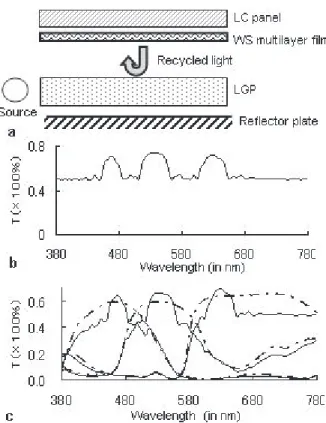
Figure 3 illustrates how the WS multilayer film can enhance color saturation of the LCD device.
Figure 3a shows a proposed configuration of the LCD employing the WS multilayer film. This figure only shows the optical components most relevant to the workings of the WS multilayer film. An edge-lit type display is shown. A light guide plate (LGP) is illuminated with the help of a light source placed to the side of the LGP.
In Fig. 3b, the wavelength spectrum of light transmit- ted from the WS multilayer film is shown. Light transmitted from the multilayer film is mostly polarized in TE mode and is composed of the light that comes out of the light source and gets transmitted directly through the multilayer film and the recycled light that comes back after reflection. The light reflected from the multilayer film is polarized mostly in TM mode and shows three peaks in the red, green and blue re- gion of the visible spectrum. The amount and polarization state of the recycled light depends on the reflection spec- trum of the reflector film at the back of the LGP and any diffuser plates or polarization converters that might be used in the path of light. The transmission spectrum in Fig. 3b is computed as the sum of directly transmitted light and the recycled light. We assume that 25% of the output is due to recycling. In comparison with Fig. 3b, the transmission spectrum of a conventional broadband multilayer film is flat.
Clearly, the use of the WS multilayer film leads to an output spectrum that depends strongly on the color of light.
The output from the multilayer film passes through the liquid crystal (LC) panel before it finally leaves the LCD de- vice and reaches the observer. The LC panel consists of at least a conventional color filter and liquid crystal cells. The
Fig. 3 Color enhancing effect of the WS multilayer film; (a) schematic diagram of the proposed LCD configuration, (b) TE mode transmission (T) spectra of the WS broadband multilayer films; (c) transmission (T) spectra of the LC panel using WS (solid) and conventional broadband (dashed) multilayer films.
color filter is composed of at least three filters; red, green and blue capable of transmitting the red, blue and green por- tions of the visible light respectively. Hence, the wavelength spectrum of the light emerging from the LC panel is deter- mined by the transmission properties of the color filter.
In Fig. 3c, the wavelength spectrum of the light coming out of the LC panel is shown. The solid line curve shows the output spectrum obtained with the WS, multilayer film. The dashed line curve is obtained with a conventional, broad- band multilayer film. A comparison between the two spectra shows that the WS multilayer film is more effective at cut- ting the light of unwanted wavelengths, and improving the color saturation of the overall display device. Thus, from the point of view of improving the color saturation, the WS multilayer film is clearly more desirable compared to the conventional, broadband multilayer film. The improvement in color saturation depends on the volume of the recycled light. The color saturation of the display device increases as the proportion of recycled light increases.
The color enhancing properties of the WS multilayer film are not limited to the LCD device model shown in Fig. 3a. A real-life LCD device includes additional com- ponents, such as, diffuser plates,λ/4 plates etc. Similarly, an actual LC panel incorporates many other components like, polarizers, compensators etc. Even with the addition of these extra components, the WS multilayer film would still remain useful in enhancing color saturation.
4. Conclusion
We presented a general design method for multilayers. A multilayer is accepted as a solution if it’s reflection prop- erties match a given target spectrum closely. The solutions are not limited to layers of optical thickness equal toλ/4.
Also, solutions can be obtained for many different shapes (different bandwidths corresponding to three peaks) of the target spectrum. In the design example provided here,Δn, the difference between refractive indices of the two layers of the basic unit along y-axis and N, the total number of layers comprising the multilayer is much smaller than those used in conventional, broadband multilayer films (typically, N ≥ 800, Δn ≥ 0.24 and layer thicknesses are less than 200 nm). The relatively smaller values for both Δn andN make such films easier and cheaper to fabricate. The wave- length spectrum of the reflectivity of the multilayer depends strongly on the value of Δn. A desirable range for Δn is 0.02 < Δn < 0.25. If Δn is greater than 0.25, reflectiv- ity becomes high and uniform for relatively broader band of wavelengths around the chosen peaks in red, green and blue region of the visible spectrum. If Δn is lesser than 0.02, reflectivity peaks are unacceptably low.
The WS multilayer film designed here is suitable for use with red, green and blue LED light sources.
If the materials of the layers of the basic units of the multilayer are optically isotropic, same wavelength- selective reflectivity is obtained in both polarization modes.
References
[1] J.A. Radford, T. Alfrey, JR., and W.J. Schrenk, “Reflectivity of iri- descent coextruded multilayered plastic films,” Polymer Engineer- ing and Science, vol.13, no.3, pp.216–221, 1973.
[2] M.F. Weber, C.A. Stover, L.R. Gilbert, T.J. Nevitt, and A.J.
Ouderkirk, “Giant birefringent optics in multilayer polymer mir- rors,” Science, vol.287, pp.2451–2456, March 2000.
[3] E. Cojocaru, “Omnidirectional reflection from finite periodic and Fi- bonacci quasi-periodic mutilayers of alternating isotropic and bire- fringent thin films,” Appl. Opt., vol.41, no.4, pp.747–755, Feb. 2002.
[4] L. Jiang, G. Zheng, L. Shi, J. Yuan, and X. Li, “Broad omnidi- rectional reflectors design using genetic algorithm,” Opt. Commun., vol.281, pp.4882–4888, 2008.
[5] H.A. Macleod, Thin-Film Optical Coating Design in Thin Films for Optical Systems, F.R. Flory (Ed.), Marcel Dekker, Inc., New York, 1995.
[6] S. Martin, J. Rivory, and M. Schoenauer, “Synthesis of optical mul- tilayer systems using genetic algorithms,” Appl. Opt., vol.34, no.13, pp.2247–2254, May 1995.
[7] E.K. Ejigu and B.M. Lacquet, “The use of a genetic algorithm in optical thin film design and optimization,” S. Afr. J. Sci., vol.106, no.7/8, pp.1–4, 2010, http://www.sajs.co.za
[8] S.M. Al-Marzoug and R.J.W. Hodgson, “Optimization of multi- layer mirrors at 13.4 nm with more than two materials,” Appl. Opt., vol.47, no.12, pp.2155–2160, April 2008.
[9] M. Born and E. Wolf, Principles of Optics, 7th (expanded) ed., Cam- bridge University press, San Francisco, 1999.
[10] S. Banerjee and L.N. Hazra, “Experiments with a genetic algorithm for structural design of cemented doublets with prespecified aberra- tion targets,” Appl. Opt., vol.40, no.34, pp.6265–6273, Dec. 2001.
Saswatee Banerjee is currently working at Advanced Materials Research Laboratory of Sumitomo Chemical Co. Ltd., Japan as a Re- search Associate. She received her Ph.D. de- grees in Applied Physics with specialization in Optics both from the University of Calcutta, In- dia and from the University of Tsukuba, Japan in 2001 and 2005 respectively. In India she was awarded Junior and Senior Research Fel- lowship by the University Grants Commission (UGC) and Council of Scientific and Industrial Research (CSIR). She was also the recipient of Ministry of Education, Cul- ture, Sports, Science and Technology Scholarship from the Japanese Gov- ernment. Her research interest is in design and simulation of optical devices that incorporate subwavelength-scale modulation. She is the co-author of thirteen peer-reviewed scientific papers and is the co-author of three book chapters.