1 適用範囲 Scope
この規格は、シリコンNチャネルパワーMOS FET MLE20について適用する。
The present specifications shall apply to silicon N-channel power MOS FET MLE20.
2 絶対最大定格
Absolute maximum ratings
項 目 Characteristic 記 号 Symbol 定 格 rating 単 位 Unit ド レ イ ン ・ ソ ー ス 電 圧
Drain to Source Voltage VDSS 150
ゲ ー ト ・ ソ ー ス 電 圧
Gate to Source Voltage VGSS ±20
V
ド レ イ ン 電 流 ( 直 流 )
Continuous Drain Current ID ±20
ド レ イ ン 電 流 ( ハ ゚ ル ス )
Pulsed Drain Current ID(pulse)
※1 ±80
A
許 容 損 失
Maximum Power Dissipation PD 150 (Tc=25℃) W
チ ャ ネ ル 部 温 度 Channel Temperature Tch 150 保 存 温 度 Storage Temperature Tstg −55∼+150 ℃ ※1 PW≦100μsec.,duty cycle≦1%
050621
SSE-23453
2/8 61426-01 3 電気的特性 Electrical characteristics 規 格 Limits 項 目 Characteristic 記 号 Symbol 条 件Test Conditions MIN TYP MAX
単位
Unit
ト ゙ レ イ ン ・ ソ ー ス 降 伏 電 圧
Drain to Source breakdown Voltage V(BR)DSS ID=100μA,VGS=0V 150 V
ケ ゙ ー ト ・ ソ ー ス 漏 れ 電 流
Gate to Source Leakage Current IGSS VGS=±20V ±100 nA
ト ゙ レ イ ン ・ ソ ー ス 漏 れ 電 流
Drain to Source Leakage Current IDSS VDS=150V, VGS=0V 100 μA
ゲ ー ト し き い 値 電 圧
Gate Threshold Voltage VTH
※ VDS=10V, ID=250μA 3.0 4.0 V
直 流 伝 達 コ ン ダ ク タ ン ス
Forward Transconductance Re(
y
fs) VDS=10V, ID=10A 7.0 11 S直 流 オ ン 抵 抗
Static Drain to Source On-Resistance RDS(ON) ID=10A, VGS=10V 0.12 0.20 Ω
入 力 容 量
Input Capacitance Ciss 1800
出 力 容 量
Output Capacitance Coss 330
帰 還 容 量
Reverse Transfer Capacitance Crss
VDS=25V VGS=0V f=1MHz 80 pF オ ン 時 遅 れ 時 間
Turn-On Delay Time
t
d(on) 75立 上 り 時 間
Rise Time
t
r 180オ フ 時 遅 れ 時 間
Turn-Off Delay Time
t
d(off) 300下 降 時 間 Fall Time
t
f ID=10A, VDD≒50V RL=5Ω, VGS=10V 図 1 参照See Fig.1 90 ns ソ ー ス ・ ド レ イ ン 間 D i 順 電 圧Source-Drain Diode Forward Voltage VSD ISD=20A,VGS=0V 1.5 V
※ VTH Rank A : 3.0∼3.2 V B : 3.2∼3.4 V C : 3.4∼3.6 V D : 3.6∼3.8 V E : 3.8∼4.0 V
図1 スイッチングタイム 測定方法
Fig.1 Switching Time Test Method
VDD≒50V ID=10A RL=5Ω VGS=10V RG=60Ω(内部抵抗) (b) 出力波形 Waveforms td(on) tr ton td(off) tf toff 90% 10% 90% 10% VGS VDS (a) 測定回路 Test Circuit ID VDS VDD RG RL VGS 0V P.W.=10μs Duty cycle≦1%
050621
SSE-23453
4/861426-01
4 外形
Package information 4-1外形、寸法および材質
Package type, physical dimensions and material
<注> ※印寸法は、リード根元部の寸法を示す。 単位:mm
Note ※ shows the dimensions measured at the bottom of lead. Dimensions in mm
15.6 ±0.3 14.0 ±0.3 13.6 ±0.2 9.6 ±0.2 5.0 MAX 2.1 MAX 1.7 +0.2-0.3 +0.2 0.6 -0.1 15.8 ±0.2 1.0 -0.1+0.2 2 +0.2-0.1 3 -0.1+0.2 2 +0.2-0.1 5.45 ±0.1 5.45 ±0.1 3.2 φ±0.1 5 .0 ± 0 .2 1 .8 ± 0 .3 2 .0 ± 0 .2 6 .0 ± 0 .2 1 9 .9 ± 0 .3 2 0 .0 M IN 3 .2 φ ± 0 .1 2 ° 2 ° 3 .5 ※ ※ ※ 名称 Description 材質 Material 仕様 Specification 樹脂 Resin エポキシ系樹脂 Epoxy resin − リード端子 Lead terminal Cu Ni メッキ・半田ディップ処理 Ni plating,solder dip treatment Solder:Pb Free Sn-3Ag-0.5Cu
(1) (2) (3) (1) ゲート Gate (2) ドレイン Drain (3) ソース Source
M L E 2 0
a) b)R
G (1) (2) (3) RG=60Ω c)4-2外観 Appearance
本体は、汚れ、傷、亀裂等なく綺麗であること。
The body shall be clean and shall not bear any stain, rust or flaw. 4-3標示
Marking
本体には、品名・ロット番号を容易に消えぬよう白色で捺印すること。
The type number and lot number shall be clearly marked in white.
a):品名標示
Type Number
b):ロット番号
Lot Number
第 1 文字 西暦年号下一桁 1st letter The last digit of year
第2文字 月 2nd letter Month 1∼9 月:アラビア数字 10 月:O 11 月:N 12 月:D (1 to 9 for Jan. to Sept., O for Oct. N for Nov. D for Dec.)
c):VTH ランク
050621
SSE-23453
6/861426-01
5 使用上の注意
Cautions and warnings
保管環境、特性検査上の取り扱い方法によっては信頼度を損なう要因となりますので、注意 事項に留意されますようお願いいたします。
Since reliability can be affected adversely by improper storage environment and handling methods during Characteristic tests, please observe the following cautions.
(1) 保管上の注意事項
Cautions for Storage
● 保管環境は、常温(5~35℃)、常湿(40~75%)中が望ましく、高温多湿や温湿度変化の大きな 場所を避けてください。
Ensure that storage conditions comply with the standard temperature (5 to 35℃) and the standard relative humidity (around 40 to 75%) and avoid storage locations that experience extreme changes in temperature or humidity.
● 腐食性ガス等の有毒ガスが発生しない塵埃の少ない場所で直射日光を避けてください。
Avoid locations where dust or harmful gases are present and avoid direct sunlight.
● 長期保管したものは、使用前に半田付け性やリードの錆等について再点検してください。
Reinspect for rush leads and solvability that have been stored for a long time.
(2) 特性検査、取り扱い上の注意事項
Cautions for characteristic Tests and Handling
● 受入検査等で特性検査を行う場合は、測定器からのサージ電圧の印加、端子間ショートや 誤接続等に十分ご注意ください。また定格以上の測定は避けてください。
When characteristic tests are carried out during inspection testing and other standard tests periods, protect the Power MOS FETs from surge of power from the testing device, shorts between the Power MOS FETs and the heatsink.
(3) シリコーングリースについて Silicone Grease ● 放熱板を取り付けてご使用になる場合は、パワーMOS FET と放熱板の間の熱抵抗を小さく するために、パワーMOS FET の裏面および絶縁板の両面にシリコーングリースを薄く均一に 塗布してください。 シリコーングリースの種類によってはオイル成分が製品内部に浸透し、製品の寿命を著しく低下 させることがありますので、シリコーングリースの選定には十分な確認を行ってください。
When using a heatsink, please coat the back surface of the power MOS FETs and both surfaces of the insulating plate with a thin layer of silicone grease to improve heat transfer between the Power MOS FETs and the heatsink.
There are types of silicone grease of which oil ingredients may permeate the inside of products. Since there is a possibility that it may shorten the lifetime of the products, please pay sufficient attention to the choice of the silicone grease.
推奨シリコーングリース
Recommended Silicone grease
● G746 (信越化学工業(株) Shin-Etsu Chemical Co., Ltd.) ● YG6260 (東芝シリコーン(株) Toshiba Silicone Co., Ltd.)
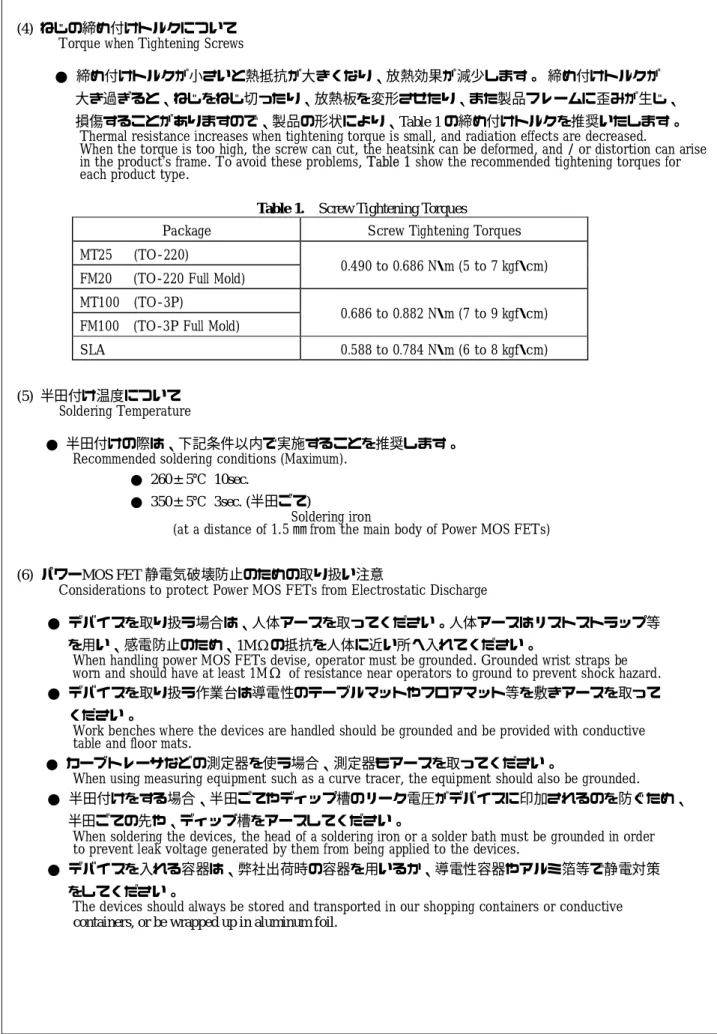
(4) ねじの締め付けトルクについて Torque when Tightening Screws
● 締め付けトルクが小さいと熱抵抗が大きくなり、放熱効果が減少します。 締め付けトルクが 大き過ぎると、ねじをねじ切ったり、放熱板を変形させたり、また製品フレームに歪みが生じ、 損傷することがありますので、製品の形状により、Table 1 の締め付けトルクを推奨いたします。 Thermal resistance increases when tightening torque is small, and radiation effects are decreased.
When the torque is too high, the screw can cut, the heatsink can be deformed, and / or distortion can arise in the product’s frame. To avoid these problems, Table 1 show the recommended tightening torques for each product type.
Table 1. Screw Tightening Torques
Package Screw Tightening Torques
MT25 (TO-220)
FM20 (TO-220 Full Mold) 0.490 to 0.686 N・m (5 to 7 kgf・cm) MT100 (TO-3P)
FM100 (TO-3P Full Mold) 0.686 to 0.882 N・m (7 to 9 kgf・cm)
SLA 0.588 to 0.784 N・m (6 to 8 kgf・cm)
(5) 半田付け温度について Soldering Temperature
● 半田付けの際は、下記条件以内で実施することを推奨します。 Recommended soldering conditions (Maximum).
● 260±5℃ 10sec.
● 350±5℃ 3sec. (半田ごて)
Soldering iron
(at a distance of 1.5 ㎜ from the main body of Power MOS FETs)
(6) パワーMOS FET 静電気破壊防止のための取り扱い注意
Considerations to protect Power MOS FETs from Electrostatic Discharge
● デバイスを取り扱う場合は、人体アースを取ってください。人体アースはリストストラップ等 を用い、感電防止のため、1MΩの抵抗を人体に近い所へ入れてください。
When handling power MOS FETs devise, operator must be grounded. Grounded wrist straps be worn and should have at least 1MΩ of resistance near operators to ground to prevent shock hazard.
● デバイスを取り扱う作業台は導電性のテーブルマットやフロアマット等を敷きアースを取って ください。
Work benches where the devices are handled should be grounded and be provided with conductive table and floor mats.
● カーブトレーサなどの測定器を使う場合、測定器もアースを取ってください。
When using measuring equipment such as a curve tracer, the equipment should also be grounded.
● 半田付けをする場合、半田ごてやディップ槽のリーク電圧がデバイスに印加されるのを防ぐため、 半田ごての先や、ディップ槽をアースしてください。
When soldering the devices, the head of a soldering iron or a solder bath must be grounded in order to prevent leak voltage generated by them from being applied to the devices.
● デバイスを入れる容器は、弊社出荷時の容器を用いるか、導電性容器やアルミ箔等で静電対策 をしてください。
The devices should always be stored and transported in our shopping containers or conductive containers, or be wrapped up in aluminum foil.
050621
SSE-23453
8/8 61426-01 (7) その他 Others ● 本書に記載されている動作例及び回路例は、使用上の参考として示したもので、これらに起因 する当社もしくは第三者の工業所有権、知的所有権、その他の権利の侵害問題について当社は 一切責任を負いません。Application and operation examples described in this document are quoted for the sole purpose of reference for the use of the products herein and Sanken can assume no responsibility for any infringement of industrial property rights, intellectual property rights or any other rights of Sanken or any third party which may result from its use.
● 本書に記載されている製品をご使用の場合は、これらの製品と目的物との組み合わせについて 使用者の責任に於いて検討・判断を行ってください。
When using the products herein, the applicability and suitability of such products for the intended purpose object shall be reviewed at the users responsibility.
● 当社は品質、信頼性の向上に努めていますが、半導体製品では、ある確率での欠陥、故障の 発生は避けられません。部品の故障により結果として、人身事故、災害事故、社会的な損害を 発生させないよう、使用者の責任に於いて、装置やシステム上で十分な安全設計及び確認を 行ってください。
Although Sanken undertakes to enhance the quality and reliability of its products, the occurrence of failure and defect of semiconductor products at a certain rate is inevitable.
Users of Sanken products are requested to take, at their own risk, preventative measures including safety design of the equipment or systems against any possible injury, death fires of or damages to the society due to device failure or malfunction.
● 本書に記載されている製品は、一般電子機器(家電製品、事務機器、通信端末機器、計測機器 など)に使用されることを意図しております。ご使用の際は、納入仕様書に署名又は押印の上 ご返却をお願い致します。高い信頼性が要求される装置(輸送機器とその制御装置、交通信号制 御措置、防災・防犯装置、各種安全装置など)への使用をご検討の際には、必ず当社販売窓口へ ご相談及び納入仕様書に著名又は押印の上、ご返却をお願い致します。極めて高い信頼性が要求 される装置(航空宇宙機器、原子力制御、生命維持のための医療機器など)には当社の文書による 合意がない限り使用しないでください。
Sanken products listed in document are designed and intended for the use as components in general purpose electronic equipment or apparatus (home appliances, office equipment, telecommunication equipment, measuring equipment, etc.). Please return to us this document with your signature(s) or seal(s) prior to the use of the products herein.
When considering the use of Sanken products in the applications where higher reliability is required (transportation equipment, and its control systems, traffic signal control systems or equipment, fire / crime alarm systems, various safety devices, etc.), please contact your nearest Sanken sales representative to discuss, and then return to us this document with your signature(s) or seal(s) prior to the use of the products herein.
The use of Sanken products without the written consent of Sanken in the applications where extremely high reliability is required (aerospace equipment, nuclear power control systems, life support systems, etc.) is strictly prohibited.
● 本書に記載された製品は耐放射設計をしておりません。