- 1 -
Physical and Electrochemical Properties of Pt Catalysts Supported
on Tin Oxide with Fused Aggregated Structure for Polymer
Electrolyte Fuel Cells
A Doctoral Thesis
Presented to the
Interdisciplinary Graduate School of Medicine and Engineering
University of Yamanashi
March 2015
- 2 -
Contents
Chapter 1
General Introduction
1.1 Background
1.1.1Fuel Cell Vehicles (FCVs)
1.1.2 Polymer electrolyte fuel cells (PEFC) 1.1.3 Concept of the catalyst layer
1.1.4 Improvements needed for popularization of FCVs
1.1.5 Review of conductive ceramics support research 1.2 Objective of the present research
1.3 References for Chapter 1
Chapter 2
Improvements in electrical and electrochemical
properties of Nb-doped SnO
2-δsupports for fuel
cell cathodes due to fused aggregation and Pt loading
2.1 Introduction 2.2 Experimental
2.2.1 Preparation and characterization of Sn0.96Nb0.04O2-δ support
and Pt/Sn0.96Nb0.04O2-δ catalyst
2.2.2 Electrochemical measurements of Pt/Sn0.96Nb0.04O2-δ catalyst
2.3 Results and discussion
2.3.1 Characterization of Sn0.96Nb0.04O2-δ support and
Pt/Sn0.96Nb0.04O2-δ catalyst
2.3.2 Conducting mechanism of Pt/Sn0.96Nb0.04O2-δ catalyst and
Sn0.96Nb0.04O2-δ support with fused aggregated network structure
2.3.3 Electrochemical characterization of Pt/Sn0.96Nb0.04O2-δ catalyst
2.4 Conclusions for Chapter 2 2.5 References for Chapter 2
4 5 6 7 8 11 13 15 17 17 20 22 22 29 37 43 44
- 3 -
Chapter 3
Cathodic performance and high potential durability of
Ta-SnO
2-δ-supported Pt catalysts for PEFC cathodes
3.1 Introduction 3.2 Experimental
3.3 Results and discussion
3.3.1 Characterization of Sn0.975Ta0.025O2-δ support and
Pt/Sn0.975Ta0.025O2-δ catalyst
3.3.2 Evaluation of cathodic properties of Pt(~15 wt.%)/Sn0.975Ta0.025O2-δ
~ a comparison of Pt/Sn0.975Ta0.025O2-δ catalyst with Pt/Sn0.96Nb0.04O2-δ catalyst ~
3.3.3 Influence of low Pt loading (~9 wt.%) on the electrochemical properties
~ a comparison of Pt/Sn0.975Ta0.025O2-δ catalyst with Pt/Sn0.96Nb0.04O2-δ catalyst ~
3.4 Conclusions for Chapter 3 3.5 References for Chapter 3
Chapter 4
General Conclusions
List of Publications
Meeting Abstracts
Patent Application
Award
Acknowledgements
46 48 49 49 53 60 66 68 70 74 75 77 77 78- 4 -
Chapter 1
General Introduction
1.1 Background
1.1.1 Fuel Cell Vehicles (FCVs)
Recently, global warming has become a world environmental issue. One of the main causative agents is carbon dioxide. To isolate and reuse emitted carbon dioxide, various techniques have been investigated. For example, the carbon dioxide capture and storage
(CCS) technique1 and the carbon dioxide chemical fixation technique2 are two
technologies that are anticipated to be used. The latter can help to convert carbon dioxide to useful chemical products. However, the fundamental solution for the environmental issue is reducing the amount of emitted carbon dioxide. From this point of view, the Japanese government has proposed the utilization of hydrogen as an alternative energy
resource, the so-called hydrogen use society.3
The amount of carbon dioxide emission from vehicles accounts for ca. 15%of the total amount for Japan,4 which cannot be ignored from the viewpoint of environmental
conservation. Given such a historical backdrop, low pollution vehicles, such as fuel-efficient internal combustion engine vehicles, hybrid vehicles of internal combustion engine and electric motor, electric vehicles (EVs) and fuel cell vehicles (FCVs), have been attracting attention. FCVs utilize fuel cells as the power source, which is a system to convert chemical reaction energy to electrical energy efficiently. Hydrogen is supplied as a fuel, and reacts with oxygen supplied from air, with low carbon dioxide emissions. EVs and FCVs are suitable for the forthcoming hydrogen use society. FCVs also have advantages to EVs in long mileage and short refuel time, and are expected to become popular on a large scale by around 2025. In anticipation, the Toyota Motor Corporation
- 5 -
started to put FCVs on the market on December 15th, 2014.
1.1.2 Polymer electrolyte fuel cells (PEFC)
The polymer electrolyte fuel cell (PEFC) is the most attractive power generation system for FCVs, because it has features such as compactness, high energy efficiency, short startup time, and low operation temperature. The PEFC includes an anode, cathode and polymer electrolyte, as shown in Fig. 1-1. At the anode, hydrogen is oxidized to protons (H+), and electrons (e-), as shown in equation (1). The protons permeate the
polymer electrolyte and arrive at the cathode. The electrons move to the cathode through the external electrical load. At the cathode, the oxygen reduction reaction (ORR) proceeds with protons and electrons, as shown in equation (2). The total reaction is shown in equation (3).
2H2 → 4H+ +4e- (1)
O2 + 4H+ + 4e- → 2H2O (2)
- 6 -
1.1.3 Concept of the catalyst layer
In order for the above reactions to proceed with low overpotential, supported Pt and Pt alloy catalysts are usually used. The cathode reaction of PEFC (eq. (2)) occurs at the three-phase (O2, H+, e-) zone located on the catalyst. Therefore, nano-sized Pt catalysts
highly dispersed on the support are required. The electrons are supplied to the Pt nanoparticles through the support materials. Oxygen diffuses through the pores of the catalyst layer. Therefore, high specific surface area, high electrical conductivity and high gas diffusivity are required for support materials. Carbon black (CB), which has a fused aggregated structure, as shown in Fig. 1-2, is a typical support material that meets these requirements. However, it has an intrinsic thermodynamic instability, as will be discussed in the next Section.
- 7 -
1.1.4 Improvements needed for commercialization of FCVs
The PEFC in an FCV experiences frequent start/stop operation, and this is a big difference from the PEFC used for residential cogeneration systems. It is known that the start/stop operation of the PEFC brings about high cathode potentials (> 0.9 V), which accelerate the degradation of the CB support following the equation (4),5,6 and that this
leads to deterioration of the PEFC performance, with agglomeration and detachment of the Pt catalyst.
C + 2H2O → CO2 + 4H+ + 4e- ; E0 = 0.207 V vs. SHE (4)
To avoid the exposure to high cathode potentials, the FCV needs various additional systems to control the potential. Developing new support materials that have high durability for high potentials is important for long lifetime and for reduction of the costs of additional systems.
- 8 -
1.1.5 Review of conductive ceramics support research
As an alternative support material to CB, various carbon materials have been
investigated,7,8 and a representative example is graphitized carbon black (GCB). Pt
catalysts supported on GCB have shown improved durability for high potentials, but the
improvement was not sufficient due to the intrinsic properties of the carbon.8
As alternative non-carbon support materials with high durability for high potentials,
a number of conductive ceramics have been examined, such as Pt/TiO2,9 Pt/TiB,10
Pt/TiN,11 Pt/In2O3–SnO2,12 Pt/Ti4O7,13 Pt/WO3,14 Pt/TiC,15 Pt/WC16 and Pt/IrO2.17 Besides
the high electrical conductivity and durability for high potentials, the conductive ceramics have to be stable under the PEFC operating conditions, for example, low pH. Sasaki et al. reported the thermochemical stability of various metal and metal oxide species via thermochemical calculations.18 A potential of 1.0 V (vs. SHE), pH = 0 and 80 °C were
assumed. They showed Sn, Ti, Nb, Ta and Sb are stable as oxides. From the point of view of electrical conductivity of these metal oxides, the Ti oxides and Sn oxides have been investigated vigorously.
One of the highly electrical conductive titanium oxides is Ti4O7 (Magneli phase).
Ioroi et al. reported that Pt supported on Magneli phase Ti4O7 was stable at high potentials
(< 1.5 V) and that a single cell with a Pt 10 wt.%/Ti4O7 cathode was operated (80°C in
0.67 V with H2/O2) successfully for 350 h.19-21 However, the electrochemical surface area
(ECSA) of Pt/Ti4O7 was far lower than that for Pt catalysts supported on conventional
carbon.21 The lower ECSA is mainly due to the low specific surface area of the Ti4O7
support (ca. 1 m2 g).20 For the preparation of the Ti4O7, reduction of the precursor under H2
gas at 900 °C is necessary. Therefore, I focused on the tin oxides as the subject of this study.
- 9 -
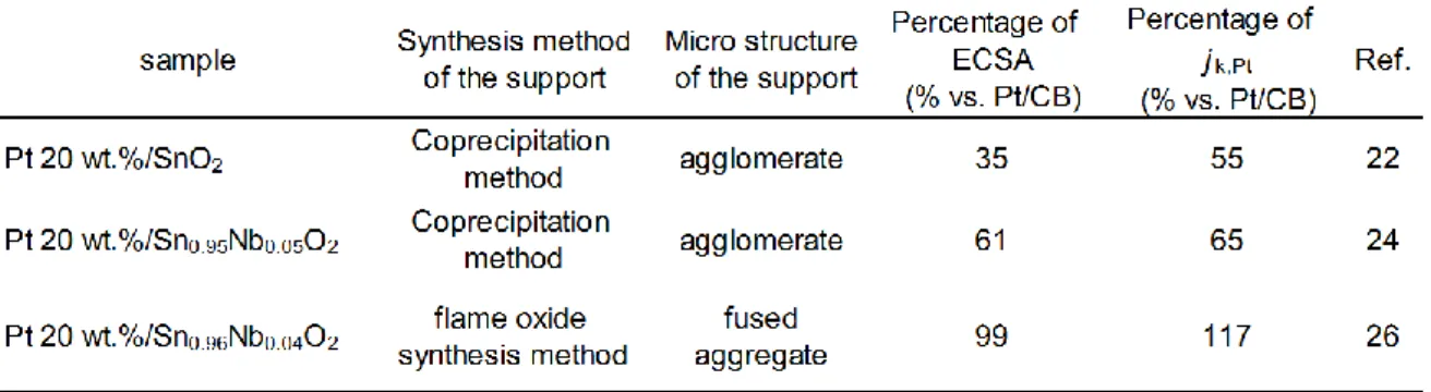
Masao et al. showed that Pt catalysts supported on SnO2 (Pt/SnO2) have high
durability under the start/stop condition.22 However, they also showed that the ECSA and
the kinetically controlled current density jk,Pt were lower than that for Pt/CB (Cabot Corp.,
Vulcan XC-72), as shown in Fig. 1-3 (a) and Fig. 1-3 (b). From the point of view of electrical conductivity, they pointed out that the donor doping (e.g., Nb5+) of the support
materials is needed for further improvement, because the SnO2 without donor doping
shows low electrical conductivity due to its wide band gap (~3.6 eV).23
Takasaki et al. prepared Nb-doped tin oxide (Nb-SnO2) and Sb-doped tin oxide
(Sb-SnO2) by the coprecipitation method.24 The powders obtained tended to agglomerate
during the coprecipitation process. The values of ECSA and jk,Pt of Pt/Nb-SnO2 are also
shown in Fig. 1-3 (a) and Fig. 1-3 (b), respectively, with the values for Pt/CB, which were obtained under the same measurement conditions as a reference. The values of ECSA and
jk,Pt of Pt/Nb-SnO2 were improved about 26 % and 10%, respectively, compared to that of
Pt/SnO2 on the basis of relative comparison with the values for Pt/CB. However, the values
were not high enough compared to the Pt/CB. They pointed out that further effort is desired to improve these values.
Kakinuma et al. reported the synthesis of nanometer-sized Nb-SnO2 and Sb-doped
SnO2, which have fused aggregated structures similar to that of the CB, by use of the flame
oxide synthesis method.25,26 The aim of developing this structure was to reduce the contact
resistance without decreasing the surface area. The ECSA of Pt/Nb-SnO2 with this unique
structure was almost the same as that for Pt/CB (TEC10E50E, Tanaka Kikinzoku Kogyo
Co.), and its jk,Pt was slightly higher than that for Pt/CB, as shown in Fig. 1-4 (a) and Fig.
1-4 (b), respectively. The preparation method and structure obtained for doped tin oxide were different between the research of Takasaki et al. and that of Kakinuma et al., as
- 10 -
mentioned above. Therefore, I supposed that the fused aggregated structure is preferable to obtain higher ORR activity.
Fig. 1-3 ECSA (a) and jk,Pt (b) of the Pt/SnO222 and Pt/Nb-SnO2(Sn0.95Nb0.05O2)24 with
the values of Pt/CB (Cabot Corp., Vulcan XC-72) which were obtained in the same measurement condition as reference. The data were read and edited from the references
22 and 24. The Pt loading was set to be 20 wt.%. The jk,Pt were measured at 0.75 V vs.
RHE.
Fig. 1-4 ECSA (a) and jk,Pt (b) of the Pt/Nb-SnO2(Sn0.96Nb0.04O2)26 with the values of
Pt/CB (TEC10E50E, Tanaka Kikinzoku Kogyo Co.). The data were read and edited
from the reference 26. The Pt loading of Pt/Nb-SnO2 was set to be 20 wt.%. The jk,Pt
- 11 -
1.2 Objective of the present research
I summarized the results of these past researches in Table 1-1. The excellent durability of the tin oxide support for high potential was already known. It was presumed that there was a strong relation among the electrochemical properties, electrical conductivity of the support material and its microstructure. However, the design guidelines in order to simultaneously produce excellent durability and excellent electrochemical properties (ECSA and jk,Pt) for the Pt catalysts supported on the tin oxide materials were
controversial. In the present research, I aimed to clarify these design guidelines to accelerate the popularization of FCVs. I paid attention to the fused aggregated structure of the support materials and their apparent electrical conductivity as key properties for high ORR activity. It seems that this structure has an advantage in reducing the contact resistance between nanoparticles.
In Chapter 2, using the Pt catalysts supported on the Nb-SnO2 with fused aggregated
structure, I tried to understand the relationships mentioned above individually. First, I investigated the relationship between the microstructure of the support material and its electrical conductivity. Then, I investigated and discussed the influence of the oxygen adsorption on the electrical conductivity of the support and Pt supported materials, because it is well known that the electrical conductivity of nanometer-sized tin oxide particles tends
to be influenced in general by the presence of adsorbed charged oxygen species.27,28 Finally,
I investigated the relationship between the electrical conductivity and the electrochemical properties (ECSA and jk,Pt).
From the results of Chapter 2, I considered that increasing the electrical conductivity of the support material by doping a more appropriate element might reduce the electron depletion layer, and that this could lead to reducing the required Pt loading to obtain the
- 12 -
same high jk,Pt with the same microstructure. According to this concept, the Pt-Pt
interparticle distance can be expanded. This will contribute to increasing the ORR activity and the durability of the Pt catalysts, in particular, for application to the membrane
electrode assembly (MEA).
In Chapter 3, in order to further improve the electrical conductivity, I prepared
Ta-SnO2 with fused aggregated structure. Then, I evaluated the cathodic activity and
durability of Pt/Ta-SnO2 catalysts and compared with Pt/Nb-SnO2 and commercial Pt/CB.
Finally, I indicated the advantages of Pt/Ta-SnO2, which originated from the improved
electrical conductivity.
From the results of these investigations, I summarized the design guidelines for the Pt catalysts supported on tin oxide materials to obtain excellent electrochemical properties as the general conclusions of this thesis in Chapter 4.
- 13 -
1.3 References for Chapter 1
1 J. Oda, K. Akimoto, F. Sano and T. Homma, Energy Procedia, 2009, 1, 155–161. 2 M. Saito, M. Takeuchi, T. Watanabe, J. Toyir, S. Luo and J. WU, Energy Convers.
Mgmt. 1997, 38 Suppl., S403–S408.
3 The Basic Energy Plan of Japan, Cabinet Council decided on April 11, 2014. Website of Agency for Natural Resources and Energy of Japan:
http://www.enecho.meti.go.jp/category/others/basic_plan/pdf/140411.pdf 4 Website of Ministry of Land, Infrastructure, Transport and Tourism of Japan:
http://www.mlit.go.jp/sogoseisaku/environment/sosei_environment_tk_000007.html 5 T. Yoda, H. Uchida and M. Watanabe, Electrochim. Acta, 2007, 52, 5997–6005. 6 T. Aoki, A. Matsunaga, Y. Ogami, A. Maekawa, S. Mitsushima, K. Ota and H.
Nishikawa, Power Sources, 2010, 195, 2182–2188.
7 H. Matsumori, S. Takenaka, H. Matsune and M. Kishida, Appl. Catal., 2010, A 373,176–185.
8 H. Yano, T. Akiyama, P. Bele, H. Uchida and M. Watanabe, Phys. Chem. Chem. Phys., 2010, 12, 3806–3814.
9 D. H. Lim, W. J. Lee, N. L. Macy and W. H. Smyrl, Electrochem. Solid-State Lett., 2009, 12, B123–B125.
10 S. Yin, S. Mu, M. Pan and Z. Fu, J. Power Sources, 2011, 196, 7931–7936. 11 B. Avasarala and P. Haldar, Electrochim. Acta, 2010, 55, 9024–9034. 12 Y. Liu and W. E. Mustain, J. Am. Chem. Soc., 2013, 135, 530–533.
13 S. Keerthi, H. Rob, C. Stephen, Y. Siyu and Z. Jiujun, Electrochim. Acta, 2012, 59, 538–547.
14 B. Wickman, M. Wesselmark, C. Lagergren and G. Lindbergh, Electrochim. Acta, 2011, 56, 9496–9503.
- 14 -
15 A. Ignaszak, C. Song, W. Zhu, J. Zhang, A. Bauer, R. Baker, V. Neburchilov, S. Ye and S. Campbell, Electrochim. Acta, 2012, 69, 397–405.
16 M. K. Jeon, K. R. Lee, W. S. Lee, H. Daimon, A. Nakahara and S. I. Woo, J. Power Sources, 2008, 185, 927–931.
17 W. Yao, J. Yang, J. Wang and Y. Nuli, Electrochem. Commun., 2007, 9, 1029–1034. 18 K. Sasaki, F.Takasaki, Z. Noda, S. Hayashi, Y. Shiratori and K. Ito, ECS Trans. 2010,
33(1), 473-482.
19 T. Ioroi, H. Senoh, S. Yamazaki, Z. Siroma, N. Fujiwara and K. Yasuda, J. Electrochem. Soc., 2008, 155, B321–B326.
20 T. Ioroi, Z. Siroma, N. Fujiwara, S. Yamazaki and K. Yasuda, Electrochem. Commun., 2005, 7, 183–188.
21 T. Ioroi, T. Akita, M. Asahi, S. Yamazaki, Z. Siroma, N. Fujiwara and K. Yasuda, J. Power Sources, 2013, 223, 183–189.
22 A. Masao, S. Noda, F. Takasaki, K. Ito and K. Sasaki, Solid-State Lett., 2009, 12, B119–B122.
23 M. Batzill and U. Diebold, Progress in Surface Science, 2005, 79, 47–154.
24 F. Takasaki, S. Matsuie, Y. Takabatake, Z. Noda, A. Hayashi, Y. Shiratori, K. Ito and K. Sasaki, J. Electrochem. Soc., 2011, 158, B1270–B1275.
25 K. Kakinuma, M. Uchida, T. Kamino, H. Uchida and M. Watanabe, Electrochim. Acta, 2011, 56, 2881–2887.
26 K. Kakinuma, Y. Chino, Y. Senoo, M. Uchida, T. Kamino, H. Uchida and M. Watanabe, Electrochim. Acta, 2013, 110, 316–324.
27 J. F. Boyle and K. A. Jones, J. Electron. Mater., 1977, 6, 717–733. 28 N. Barsan and U. Weimar, J. Electroceram., 2001, 7, 143–167.
- 15 -
Chapter 2
Improvements in electrical and electrochemical
properties of Nb-doped SnO
2-δsupports for fuel cell
cathodes due to fused aggregation and Pt loading
2.1 Introduction
The background and objectives of this research were described in Chapter 1. I will summarize them here briefly here. Pt/CB is a one of the typical catalysts for the cathode of the PEFC for FCVs. However, carbon has an intrinsic thermodynamic instability as a result of its oxidative corrosion to carbon dioxide under the typical PEFC operating conditions of low pH and high humidity, as shown in equation (4).1,2 Operation in the higher potential
range (> 0.9 V), particularly under automotive start/stop conditions, accelerates the degradation of the cathode catalyst and leads to the deterioration of the PEFC performance.1,2 The development of alternative supports to carbon with high electrical
conductivity and stability in the high potential range is very important to ensure the success
of fuel cell commercialization. Doped tin oxide materials such as Nb-SnO2-δ and Sb-SnO2-δ
are some of the principal candidates.3-8 From the results of this research described in
Section 1-2, it seems that there is a strong relation among the electrochemical properties, the electrical conductivity of the support material and its microstructure. It is also well known that the electrical conductivity of nanometer-sized tin oxide particles tends to be influenced in general by the presence of adsorbed charged oxygen species,9,10 suggesting
that the influence of the oxygen on the electrical conductivity of the Pt supported on doped tin oxide should be evaluated.
- 16 -
In the present research, I aimed to clarify the design guidelines of microstructure for
the highly activated Pt catalysts supported on the Nb-SnO2-δ with fused aggregated
structure. In this Chapter, first of all, I investigated the relationship between the microstructure of the support material and its apparent electrical conductivity. Then, I evaluated the effect of the loaded Pt nanoparticles on the apparent electrical conductivity and the influence of the oxygen adsorption on the apparent electrical conductivity of the support. Finally, I investigated the relationship between the apparent electrical conductivity and the electrochemical properties, and elucidated the appropriate fused aggregated
network structure of the Pt/Nb-SnO2-δ, which showed higher oxygen reduction reaction
- 17 -
2.2 Experimental
2.2.1 Preparation and characterization of Sn
0.96Nb
0.04O
2-δsupport
And Pt/Sn
0.96Nb
0.04O
2-δcatalyst
I synthesized the Nb-doped SnO2-δ support, with an fused aggregated network
structure similar to that of CB, by a flame oxide-forming method.7,8 Tin 2-ethylhexanoate
Sn(C7H15COO)4 and niobium 2-ethylhexanoate Nb(C7H15COO)5 were used as starting
materials. These materials were mixed at the desired mole ratio and were dissolved in terpene oil or 2-ethylhexanoic acid. These solutions were mixed by use of a magnetic stirrer for 2 h at room temperature. The obtained solutions were supplied to an atomizer at
a rate of 1.4 - 3.4 g min-1 by a peristaltic pump and were injected into a flame with oxygen
gas at a rate of 9 L min-1. The temperature of the flame, which was generated by propane
(1 L min-1) and oxygen (5 L min-1), was about 1400 oC, as measured by an infrared
radiation thermometer (IR-CAQ2CS, Chino Co.). The gas flow rates mentioned above were maintained constant for all samples to unify the oxidation conditions. The entire oxidation reaction lasted for about one hour, and ca. 10 g of powder was collected with a high efficiency particulate air (HEPA) filter. Pt nanoparticles were loaded on the Nb-doped
SnO2-δ by a colloidal method.11-13 The as-prepared catalysts were heat-treated at 150 oC in
a 1%-H2 (balance N2) atmosphere for 2 h and quenched to room temperature under the
same atmosphere.
Crystallographic structures and crystallites sizes of the obtained Nb-doped SnO2-δ
were confirmed by X-ray diffraction measurements (XRD, Ultima 4, Rigaku Co.) with Cu Kα radiation (0.15406 nm, 40 kV, 40 mA). The crystallite size of the Nb-doped SnO2-δ
particles was also evaluated with XRD by examining the peak at 2θ ~33.9°.
- 18 -
electron microscopy (TEM, H-9500, Hitachi High-Technologies Co.). The average particle diameters and size distributions of the Pt nanoparticles were also estimated from the TEM images.
The surface area of the oxide support was estimated by the Brunauer, Emmett and Teller absorption method (BET, BELSORP-max, Nippon BEL Co.). The amount of the supported Pt catalyst and chemical composition of Sn and Nb in the support were quantitatively analyzed by use of an inductively coupled plasma-mass spectrometric analyzer (ICP-MS, 7500CX, Agilent Technologies Inc.). The analysis of the Pt content was carried out with aqueous solutions that were prepared by the dissolution of the Pt catalysts in hot aqua regia. The analysis of Sn and Nb was carried out with an aqueous hydrochloric acid solution, which was prepared after a pretreatment of the support by the alkaline fusion method (sodium carbonate and sodium peroxide).
The apparent electrical conductivity measurement was performed under ambient air atmosphere with the two probe method. The support powders were placed into a cylinder with a radius of 1 cm, and aluminum foil electrodes were placed at the top and bottom of the column of support powder. The electrical resistance was measured under an applied pressure (19 MPa) with a DC resistivity analyzer (Ohm Tester Model 3565, Tsuruga Electric Co.). The apparent electrical resistivity of the sample was estimated from the slope of the relationship between resistance and sample thickness.
The pore size distribution of the support particles was measured by mercury intrusion porosimetry (AutoPore IV 9520, Micromeritics Co.) to evaluate the pore volume and variation of the network structure of the Sn0.96Nb0.04O2-δ. The mercury intrusion
pressure was applied from 3.0 × 10⁻³ MPa to 4.1 × 10² MPa. The intrusion curves showed
- 19 -
defined as primary pores, formed between the fused aggregated oxide particles, and larger ones as secondary pores, formed between the agglomerates of the fused aggregates, in the
- 20 -
2.2.2 Electrochemical measurements of Pt/Sn
0.96Nb
0.04O
2-δcatalyst
A cyclic voltammetric (CV) measurement for the determination of electrochemical surface area (ECSA) and a linear sweep voltammogram for the measurement of the oxygen reduction reaction (ORR) activity were performed with the rotating disk electrode (RDE), respectively. The catalyst was uniformly dispersed on the glassy carbon substrate (RDE electrode, 5 mm in diameter) by delivering an appropriate amount of a mixed solution of ethanol and water (9 : 1 volume ratio), in which the catalyst was suspended, for a constant loading of Pt, 11 mg cm-2. Then, a suspension of 5 wt.% Nafion® diluted with a mixed
solution of ethanol and water (9 : 1 volume ratio) was spread evenly over the catalyst layer
to yield an average film thickness of 50 nm. The Nafion® coated electrode was dried in air
under a high ethanol vapor pressure at room temperature for 12 h. The counter electrode was a platinum wire. The potential of the working electrode was referenced to a reversible hydrogen electrode (RHE) immersed in the same solution. The electrolyte solution of 0.1
M HClO4 was prepared from reagent grade chemicals (Kanto Chemical Co.) and Milli-Q
water (ultrapure water, 18.2 MΩ cm, Milli-Pore Japan Co.). A potentiostat (HZ-5000, Hokuto Denko Co.) was used for the CV and linear sweep voltammetry (LSV) measurements. Before carrying out the CV measurement, the catalyst dispersed on the RDE electrode were subjected to 60 potential cycles from 0.05 V to 1.15 V vs. RHE at a
sweep rate of 0.2 V s-1 to remove impurities from the surface of the catalyst. After these
potential cycles, the electrolyte solution was replaced with fresh solution. The CV was
recorded by sweeping the potential from 0.05 to 1.0 V vs. RHE at 0.1 V s-1 at 25 oC. The
electrolyte solution was purged with N2 gas for at least 1 h prior to the CV measurements.
The ECSA of Pt was evaluated from the electrical charge for the hydrogen adsorption (QH)
- 21 -
V s-1, after subtraction of the double layer charge (QDL),14 assuming QH = 0.21 mC cm-2
conventionally adopted for smooth polycrystalline platinum.15,16 The ORR measurement
was conducted by LSV, sweeping the potential from 0.25 to 1.0 V vs. RHE at 5 mV s-1 at
rotation rates in the 1000 – 2750 rpm range at 25 oC. The electrolyte solution was saturated
- 22 -
2.3 Results and discussion
2.3.1 Characterization of Sn
0.96Nb
0.04O
2-δsupport and Pt/Sn
0.96Nb
0.04O
2-δcatalyst
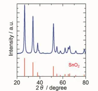
The XRD pattern of a Sn0.96Nb0.04O2-δ support powder representative of the eleven
powder samples synthesized by the flame oxide synthesis method is shown in Fig. 2-1. All peaks were assigned to those of rutile-type SnO2-δ, without any impurity phase such as
Nb2O5. I did not detect a clear peak shift, so there is no direct XRD evidence for
Nbdoping; this could perhaps be expected, since the ionic radii of Sn4+ (0.69 Å) and Nb5+
(0.64 Å), for the case of a coordination number of six, are quite similar.17 The Nb
concentration was determined to be Sn:Nb = 0.96 : 0.04 (mol%, Sn0.96Nb0.04O2-δ) from the
ICP-MS result. The BET surface areas of the obtained powders ranged from 37 m2 g-1 to
105 m2 g-1. I considered the electrical conductivity of these nanoparticles to be strongly
influenced by necking between nanoparticles. I evaluated the level of necking between
nanoparticles with a “necking index” (NI = SBET/SXRD), defined by the ratio of the specific
surface area measured by the conventional BET method (SBET) to the surface area
estimated by assuming a spherical shape in a non-necked state, with the mean crystallite
size determined by the XRD method (SXRD). A decrease of the value below NI = 1.0
indicates the development of necking compared with the separated particle state. The oxide nanoparticles exhibited NI values from 0.91 to 0.67, indicating the presence of nanoparticles aggregated to various extents. Fig. 2-2(a) and (b) show TEM images for typical nanoparticles with different NI values, 0.91 and 0.83, respectively. The former (a) appears to have a close-packed aggregated structure and the latter (b) a chain-like fused aggregated structure. It is clear from the high resolution TEM image of Fig. 2-2(c) that
- 23 -
each oxide nanoparticle was made up of well crystallized particles, without any amorphous
layer, which could have been detected by in a phase contrast images.7 I also detected the
lattice plane of (101) in Fig. 2-2(d). The existence of these high-quality crystallites relies
on the high temperature (1400 oC) sintering in the flame oxide-forming method. Moreover
the obtained particles consisted of necked particles, with diameters ranging from about 10 nm to 30 nm, forming an fused aggregated network structure and primary pores, as defined
below in the Experimental section, similar to that of carbon blacks.14 The development of
necking, comparing state (a) and (b) in Fig. 2-2, brought about an increase of the primary
pore volume, i.e., 0.165 mL g-1 to 0.215 mL g-1. I considered that the fused aggregation of
the oxide nanoparticles, which correlated quantitatively with the NI values and pore volume, must change the electronic conductivity and also the electrocatalytic activity for the ORR.
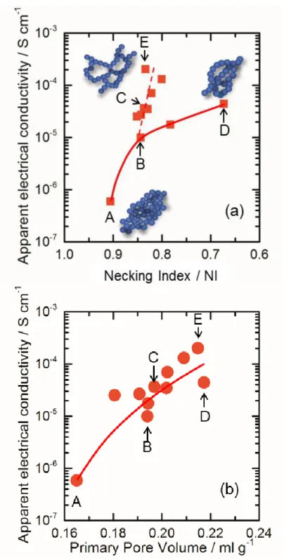
The apparent electrical conductivity of the obtained nanoparticles was plotted as a function of the value of NI and the volume of the primary pores, respectively, in Fig. 2-3(a) and (b). The values of electronic conductivity were from 5.9×10⁻⁷ to 2.0×10⁻⁴ S
cm-1; these were much higher than that of Nb-free tin oxide (5.5×10⁻⁹ S cm-1, NI: 0.81,
primary pore volume 0.19) prepared by the same synthesis conditions as those of sample C. I consider that this result indicates Nb-doping. In Fig. 2-3(a), I found that the apparent electrical conductivity of the nanoparticles generally increased with increasing NI but exhibited two distinctly different types of dependence, e.g., one type including samples B and D, and a second type including samples C and E, shown in the figure. A very interesting discovery was that the enhancement of the electrical the NI value for sample E was much higher than that for sample D. Fig. 2-3(b) clearly shows that the electrical conductivity increased with increasing primary pore volume. The electrical conductivity of
- 24 -
a porous material has a tendency to increase with the development of a fused aggregated network structure, also accompanied by an increase of the primary pore volume, due to the
network being formed with nonlinear fused aggregation.14,18 I also found that the
microstructure of the Sn0.96Nb0.04O2-δ nanoparticles changed from a close-packed,
aggregated type to a chain-like, fused aggregated type with increasing primary pore volume, as seen in Fig. 2-2(a), (b) and Fig. 2-3(a), (b). These results indicate that the chain-like fused aggregated structure would be preferable for the PEFC electrode.
Therefore, I selected several of the Sn0.96Nb0.04O2-δ support powders (samples A–E)
shown in Fig. 2-3 and deposited Pt catalyst nanoparticles on them (denoted as Pt/Sn0.96Nb0.04O2-δ). The Pt nanoparticles were highly dispersed over the surface on each
support, as shown in the TEM images (Fig. 2-4). The Pt particle sizes and the amounts of Pt loading were also controlled within a narrow range (particle diameter, 2.6 ± 0.5 nm to 3.1 ± 0.5 nm; Pt loading, 15.2 wt.% to 17.3 wt.%) for each catalyst, regardless of the differences in NI or the primary pore volume. The distances between Pt nanoparticles were controlled to be within the range of 8.3 to 11.5 nm (Table 2-1).
The apparent electrical conductivities of the Pt-loaded oxide catalysts under air are plotted as a function of the primary pore volume of these supports in Fig. 2-5, together with the conductivities for the corresponding oxide supports without Pt loading (samples A–E), taken from Fig. 2-3. I found that the apparent electrical conductivities of the Pt-supported catalysts were enhanced greatly, by more than two orders of magnitude
compared to those of the supports alone. These Pt/Sn0.96Nb0.04O2-δ catalysts and
Sn0.96Nb0.04O2-δ supports were heat-treated under the same conditions described in the
Experimental section, and had the same content of aliovalent cation dopant. The electrical conductivity of nanometer-sized metal oxide particles tends to be influenced in general by
- 25 -
the presence of adsorbed molecules,9,10 as will be discussed in the next section.
Fig. 2-1. X-ray diffraction pattern for Sn0.96Nb0.04O2-δ. All peaks were assigned to
those of rutile-type SnO2-δ without any impurity phase such as Nb2O5. The XRD
profile of rutile-type SnO2-δ (International Centre for Diffraction Data, Powder
Diffraction File (ICDD PDF):01-088-0287) is also displayed for reference.
Fig. 2-2. Transmission electron microscopy image of Sn0.96Nb0.04O2-δ particles: (a)
close-packed aggregated type (sample (A), NI 0.91, primary pore volume 0.165 mL g-1),
(b) chain-like fused aggregated type (sample (E), NI 0.83, primary pore volume 0.215 mL g-1), (c) high resolution TEM image of the Sn0.96Nb0.04O2-δ particles (sample (E)), (d)
- 26 -
Fig. 2-3. Apparent electrical conductivities of Sn0.96Nb0.04O2-δ particles as a function of
necking index (a) and primary-pore volume (b), where the symbols A-E indicate the oxide supports used for further studies below as Pt supported on sample A-E. Schematic drawings in Fig. 2-3(a) are artistic representations of the respective aggregated network samples.
- 27 -
Fig. 2-4. Transmission electron microscopic images of Pt/ Sn0.96Nb0.04O2-δ particles:
(A) sample A, (B) sample B, (C) sample C, (D) sample D, (E) sample E. The notation (A to E) corresponds to that of Tables 2-1 and 2-2.
Oxide Support Primary pore Volume / ml g-1 σapp. without Pt loading / S cm-1 σapp. with Pt loading / S cm-1 Pt loading / wt % Pt particle size / nm Pt-Pt distance / nm A 0.165 5.9×10⁻⁷ 5.2×10⁻⁴ 15.2 2.6 ± 0.5 11.5 B 0.194 9.9×10⁻⁶ 5.3×10⁻³ 17.3 3.0 ± 0.5 10.8 C 0.197 3.7×10⁻⁵ 1.3×10⁻² 16.9 2.9 ± 0.5 10.0 D 0.217 4.4×10⁻⁵ 1.8×10⁻² 16.9 3.1 ± 0.5 8.3 E 0.215 2.0×10⁻⁴ 1.3×10⁻² 16.9 3.0 ± 0.5 9.2
Table 2-1. Pt loading, Pt particle size, and Pt intercrystallite distance of Pt
nanoparticles supported on the Sn0.96Nb0.04O2-δ (Pt/ Sn0.96Nb0.04O2-δ) after heat treatment
at 150 oC in 1% H2 atmosphere for 2 h. Five Sn0.96Nb0.04O2-δ supports with various
aggregated network structures, which were designated samples A, B, C, D, E, are shown
in Fig. 2-3. σapp.. is defined as an apparent electrical conductivity measured under
- 28 -
Fig. 2-5. Apparent electrical conductivities of Sn0.96Nb0.04O2-δ particles and Pt/
Sn0.96Nb0.04O2-δ particles in air atmosphere plotted with primary pore volumes, where
- 29 -
2.3.2 Conducting mechanism of Pt/Sn
0.96Nb
0.04O
2-δcatalyst and
Sn
0.96Nb
0.04O
2-δsupport with fused aggregated network structure
As a factor that sensitively affects the electrical conductivity of tin oxide, the effect
of chemisorbed, charged oxygen species (O2-, O-, O2-) can be generated by the reduction of
oxygen molecules by electrons supplied from the tin oxide.9,10 Therefore, I examined in
more detail the sensitivity of the electronic conductivity of the Sn0.96Nb0.04O2-δ powders
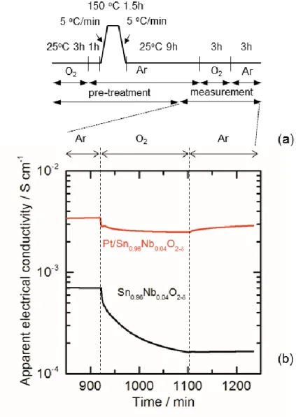
with/without Pt loading under various gas atmospheres. The representative sample powders, taken from sample C with/without Pt, were pressed into a rectangular shape and
were pre-treated at 150 oC under argon for 1.5 h in order to desorb the adsorbed molecules
on the surface, following a reported procedure,10 and then cooled in an argon atmosphere.
Then, the atmosphere was replaced with pure oxygen for 3 h and then replaced by argon again, as shown by the sequence of temperature and atmosphere treatments in Fig. 2-6(a).
During this sequence, the electrical conductivities at 25 oC were monitored without
exposure to the ambient atmosphere. The results are shown in Fig. 2-6(b). I found an abrupt but slight decrease of the electrical conductivity at Pt/Sn0.96Nb0.04O2-δ as the
atmosphere was changed to oxygen, but the conductivity recovered slowly after changing
back to an argon atmosphere. However, the conductivity of the Sn0.96Nb0.04O2-δ decreased
markedly, reaching a value of only 25% compared to the initial value. It exhibited almost no recovery after changing from oxygen back to the argon atmosphere. Moreover, the electronic conductivity at Pt/Sn0.99Nb0.01O2-δ powder increased with increasing amount of
Pt loading, as shown in Fig. 2-7.
As shown in Fig. 2-6, the electrical conductivity of nano-sized tin oxide particles
- 30 -
and CO would also affect the conducting behavior in both Sn0.96Nb0.04O2-δ and
Pt/Sn0.99Nb0.01O2-δ powder, but these chemical substances and related ones were not
detected from the H2-reduced Pt/Sn0.96Nb0.04O2-δ powders by temperature-programmed
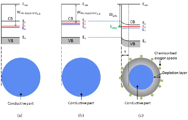
desorption (TPD) measurements. From these results, I focused on the oxygenated species to be the main chemisorbed molecules. The oxygen species such as charged oxygen species (O2-, O-, O2-), are generated by the reduction of oxygen molecules by electrons
supplied from the tin oxide, thereby introducing a depletion layer, with band bending, on
the surface of the oxide,10 as shown in Fig. 2-8(a)~(c). The band bending in the depletion
layer enhances the grain boundary resistance and interparticle resistance of nanoparticles,
thus obstructing the electron conduction in the oxide.10,19 I consider that the Pt
nanoparticles might lower the influence of adsorbed oxygen species on the charge carriers on the tin oxide nanoparticle surface.
The grain boundary and interparticle resistances decreased with the development of necking (Fig. 2-9(a) and (b)).10 Moreover, our results (Fig. 2-6(b)) indicate that Pt
nanoparticles lowered the influence of adsorbed oxygen species on the Sn0.96Nb0.04O2-δ
nanoparticle surface, for example, by dissociating molecular oxygen, avoiding its reduction to superoxide, which would lead to the depletion of conduction electrons associated with
the Nb dopant, by analogy with similar phenomena for titanium dioxide.19 The result
would be to shrink the depletion layer, along with the relief of band bending (Fig. 2-9(c)), and the suppression of the grain boundary and interparticle resistances.
As an example of the investigation of the effect of the Pt nanoparticles, I show the
Raman spectra of Pt/Sn0.99Nb0.01O2-δ with various Pt loadings (same samples as in Fig. 2-7)
in Fig. 2-10. The Raman spectra for each sample (wavelength λ = 633 nm, room temperature, in air) were obtained as an average ones of five sets of raw data, and were
- 31 -
normalized by the intensity of the peak at approximately 630 cm-1. The blue lines show the
wavenumbers of the representative Raman-active modes (A1g, Eg, B2g) of SnO2.20 The red
lines show the wavenumbers of the Raman-forbidden modes (A2uTO, A2uLO, B1u) of
SnO2.20 The Raman-forbidden modes are attributed to the decrease of crystallite size and
increase of disorder (decreasing crystal symmetry).20 Sn0.99Nb0.01O2-δ without Pt showed a
sharp band around the A1g mode. The shift of the band to lower wavenumber is usually
explained by a decrease of the crystallite size to the nanoscale.21 Pt/Sn0.99Nb0.01O2-δ showed
a broad band from ca. 800 cm-1 to ca. 400 cm-1, with an increase of intensity around the
Raman-forbidden modes. The crystallite sizes of the support estimated by XRD were
nearly the same for Sn0.99Nb0.01O2-δ (19.4 nm) and H2-reduced Pt 16.3
wt.%/Sn0.99Nb0.01O2-δ (19.3 nm). I consider that these changes of the Raman peaks are
related to the effect of the oxygen vacancies, which were induced by the Pt loading on the Sn0.99Nb0.01O2-δ. The generation of oxygen vacancies also induces a thinning of the
depletion layer, which is based on the proportional relationship between thickness of depletion layer and N -1/2 (N, concentration of the dopant). Further investigations of
charged oxygen species are needed in the future. Electron spin resonance (ESR) would be one of the essential techniques for the characterization of the detailed effects of the charged oxygen species.
- 32 -
Fig. 2-6. Apparent electrical conductivity of Sn0.96Nb0.04O2-δ and Pt/ Sn0.96Nb0.04O2-δ
monitored under Ar and O2 atmospheres. (a) the sequence shows the temperature and
atmosphere during the heat treatment and conductivity measurements, (b) variation of the apparent electrical conductivity of Sn0.96Nb0.04O2-δ and Pt/Sn0.96Nb0.04O2-δ by
changing atmospheric conditions. Each sample was pre-treated at 150 oC in argon and
cooled to room temperature under the same atmosphere, without exposure to the ambient atmosphere.
- 33 -
Fig. 2-7. Apparent electrical conductivities of Pt/Sn0.99Nb0.01O2-δ particles in air
- 34 -
Fig. 2-8. Schematic band model of Nb-doped tin oxide.
(a) Nb-doped tin oxide without oxygen vacancies and adsorbed species, (b) Nb-doped tin oxide with oxygen vacancies and without adsorbed species, (c) Nb-doped tin oxide with oxygen vacancies and chemisorbed oxygen species,
CB: conduction band, VB: valence band, EC: conduction band minimum; EF, Fermi level,
EV: valence band maximum, ED: donor level (originated from Nb and oxygen vacancy)
Eoxy: level of the chemisorbed oxygen specie t: thickness of electron depletion layer,
WNb-doped SnO2-δ: work function of Nb-doped tin oxide, Wads: work function of Nb-doped tin
oxideafter oxygen molecule adsorbed, gray area: electron depletion layer of Nb-doped tin
oxideparticles, blue area: Nb-doped tin oxideparticles without electron depletion layer.
Nanoparticle tends to have oxygen vacancies at its surface. Oxygen vacancies would shift up the donor level to a certain degree, as shown in model (b), because oxygen vacancies can provide electrons to the host oxide.
- 35 -
Fig. 2-9. Schematic model of depletion region for (a) Nb-doped tin oxide particles; (b)
Nb-doped tin oxideparticles with developed necking; and (c) Pt dispersed on Nb-doped
tin oxideparticles with developed necking. The depletion region around the interface
between Nb-doped tin oxideparticles disappears partially due to the necking, as shown,
comparing (a) and (b). The depletion region also decreased due to Pt loading because of decreased amounts of charged species (c).
- 36 -
Fig. 2-10. Raman spectra of Pt/Sn0.99Nb0.01O2-δ with various Pt loadings.
The spectra for each sample (wavelength λ = 633 nm, room temperature, in air) were obtained as averages of five sets of raw data and were normalized by the intensity of
the peak at approximately 630 cm-1. Blue lines show wavenumbers of representative Raman
active modes (A1g, Eg, B2g) of SnO2. 20
Red lines show wavenumbers of Raman-forbidden modes (A2uTO, A2uLO, B1u) of SnO2.
20
- 37 -
2.3.3 Electrochemical characterization of Pt/Sn
0.96Nb
0.04O
2-δcatalyst
Figure 2-11 shows the CVs for the Pt/Sn0.96Nb0.04O2-δ measured by the RDE in 0.1
M HClO4 solution saturated with N2 at 25 oC. The hydrogen adsorption/desorption peaks
appear clearly. The ECSA values, which were evaluated based on the hydrogen adsorption on Pt particle surfaces, are listed in Table 2-2.
Anodic current due to oxide formation on the platinum surface also appeared above 0.7 V vs. RHE. These peak positions correspond well to those for the commercial Pt/CB or Pt/GCB for the similar potential sweep range (0.05 V to 1.0 V vs. RHE), as reported in
previous work.22 The inset in Fig. 2-12 shows the initial hydrodynamic voltammograms for
the ORR for each Pt/Sn0.96Nb0.04O2-δ sample, by the use of the RDE technique at 1750 rpm,
in 0.1 M HClO4 solutions saturated with oxygen at room temperature.
The onset potentials for ORR at these catalysts were all ca. 0.98 V, and the ORR current approached the diffusion limiting value at around 0.5 V. The effect of the solution phase mass transport was removed with plots of the inverse current vs. the inverse of the
square root of rotation rate (ω-1/2) obtained from these current–potential curves, based on
the Koutecky–Levich equation.23 Linear relationships with a constant slope were obtained
at 0.80 V vs. RHE for the Pt/Sn0.96Nb0.04O2-δ catalysts (Fig. 2-12). By extrapolating ω-1/2 to
0 (infinite mass transport rate), the kinetically controlled currents Ik were determined.
Using these data, the kinetically controlled current densities based on real Pt area per unit geometric area (jk,geo/(APt/Ageo) = jk,Pt) were determined. The jk,Pt values at 0.80 V for
Pt/Sn0.96Nb0.04O2-δ increased with increasing apparent electrical conductivity of the
Pt/Sn0.96Nb0.04O2-δ catalyst and slightly exceeded that for a commercial Pt/CB catalyst24
(Fig. 2-13). From these results, it is deduced that, roughly estimated, the required electrical conductivity for the high jk,Pt is ca. 1×10⁻² S/cm (under an applied pressure of 19 MPa).
- 38 -
The data of Fig. 2-13 were measured at a potential of 0.80 V, where the charge transfer reaction is dominant for the ORR. It is proposed that the charge transfer reaction,
as shown in equation (5), is the rate-determining step of the ORR for the Pt catalyst. 25 The
rate of electron supply has a major impact on the reaction rate of eq. (5). It is presumed that the rate of electron supply is correlated with the number of conducting electrons of the support material. Therefore, it is presumed that the reaction rate of eq. (5) on the Pt/Sn0.96Nb0.04O2-δ catalyst, which has a low apparent electrical conductivity, is lower than
that for the commercial Pt/CB due to an insufficient number of conducting electrons. Then, increasing the apparent electrical conductivity of the Pt/Sn0.96Nb0.04O2-δ catalyst
leads to an increase of the reaction rate of eq. (5) according to the same logic, and this improves the jk,Pt values. Sufficient apparent electrical conductivity (sufficient number of
conducting electrons) will saturate the jk,Pt values due to the maximum activity of the
catalyst.
Oad + H+ + e- → OHad (5)
On the other hand, there is no correlation between the ECSA value and the apparent electrical conductivity, as shown in Fig. 2-14. The high ECSA value was obtained even though the apparent electrical conductivity was low. The hydrogen adsorption/desorption peaks appear clearly, with a fraction of the current of the ORR, and therefore it seems that the ECSA value is not susceptible to the lack of apparent electrical conductivity.
From the discussion of the difference of the amounts of current between the ORR and the hydrogen adsorption/desorption reactions, the decrease of the utilization rate of Pt
- 39 -
the poorly conductive sample (Fig. 2-13). If there are locally highly resistive area in the catalyst layer, the current throughout the layer will decrease. There is a possibility that Pt catalysts in such areas will only contribute to the hydrogen adsorption/desorption reaction. It is considered that poorly conductive samples, with insufficiently fused aggregated structure, have a tendency to include the locally highly resistive areas because of the contact resistance, grain boundary resistance and the influence of chemisorbed oxygen species, as explained in Fig. 2-9. The samples shown in Fig. 2-4, (A) and (B), which have a close-packed aggregated type of structure (insufficiently fused aggregated structure) correspond to the two poorly conductive samples. The jk,Pt values of these samples were
less susceptible to an increase of the apparent electrical conductivity. This may be due to the low utilization rate of Pt involved in the ORR, that is, even if the reaction rate of eq. (5) increases with increasing apparent electrical conductivity, the number of Pt particles involved in the ORR does not increase or only slightly increases. It is presumed that the relationship shown in Fig. 2-13 is peculiar to the electrocatalysts using electrically conductive ceramic nanoparticle supports whose apparent electrical conductivity is lower than that for CB.
From these results and discussion, I consider that the fused aggregated network structure for the Sn0.96Nb0.04O2-δ support, with well-dispersed Pt nanoparticles, is important
for the development of electrocatalysts for polymer electrolyte fuel cells in order to obtain Pt catalysts with high ORR activity.
- 40 -
Fig. 2-11. Cyclic voltammograms for Pt/ Sn0.96Nb0.04O2-δ obtained at a sweep rate
of 0.1 V s-1 in N2-saturated 0.1 mol dm-3 HClO4. The notation of A-E corresponds
to that of Tables 2-1 and 2-2.
Table 2-2. The ECSA and the kinetically controlled current densities at 0.80 V on Pt/Sn0.96Nb0.04O2-δ with different network-structure supports, A-E.
- 41 -
Fig. 2-12. Hydrodynamic voltammograms for the ORR on Pt/ Sn0.96Nb0.04O2-δ, which
were recorded by sweeping the potential from 0.05 to 1.00 V at 0.05 V s-1 at a rotation rate of 1750 rpm at room temperature. The notation of A-E corresponds to that of Tables 2-1 and 2-2.
Fig. 2-13. Kinetically controlled current densities based on real Pt area of Pt/ Sn0.96Nb0.04O2-δ at 0.80 V plotted as a function of the apparent electrical
conductivities. The apparent electrical conductivity of a commercial Pt/CB catalyst
(TEC10E50E, Tanaka Kikinzoku Kogyo Co.) was found to be 14 S cm-1 by use of
the same measurement method.
- 42 -
Fig. 2-14. Electrochemical surface area (ECSA) plotted as a function of the apparent electrical conductivities.
- 43 -
2.4 Conclusions for Chapter 2
I evaluated the electrical conductivity of Sn0.96Nb0.04O2-δ nanoparticle supports with
fused aggregated network structures similar to that of CB and the corresponding Pt/Sn0.96Nb0.04O2-δ catalysts. The electrical conductivities of the Sn0.96Nb0.04O2-δ
nanoparticle supports increased strikingly, i.e., by two orders of magnitude, with increasing particle necking and primary pore volume, with the microstructure of the support progressing from a close-packed aggregated type to a chain-like fused aggregated type. I propose the formation of the electronically conducting paths constructed by the Sn0.96Nb0.04O2-δ nanoparticles in the chain-like fused aggregates. Moreover, I found that the
electrical conductivities of the Pt/Sn0.96Nb0.04O2-δ samples measured at room temperature in
air were enhanced further by more than two orders of magnitude compared to the corresponding Sn0.96Nb0.04O2-δ supports without Pt loading. The electrical conductivity of
Pt/Sn0.96Nb0.04O2-δ was not as susceptible to oxygen as was the Sn0.96Nb0.04O2-δ
nanoparticle support. I consider that Pt nanoparticles might lower the influence of adsorbed oxygen species on the Sn0.96Nb0.04O2-δ nanoparticle surface, which would relate to the
improvement of the electrical conductivity of Pt/Sn0.96Nb0.04O2-δ. The electrochemical
activity of the Pt/Sn0.96Nb0.04O2-δ samples improved with increasing electrical conductivity
and exceeded that of a commercial Pt catalyst supported on carbon black (Pt/CB). Thus, I conclude that both the development of necking between oxide nanoparticles by fusion of nearest-neighbor particles to form a chain-like fused aggregated structure and the presence of well-dispersed Pt nanoparticles are preferred for the enhancement of the electrochemical activity.
- 44 -
2.5 References for Chapter 2
1 T. Yoda, H. Uchida and M. Watanabe, Electrochim. Acta, 2007, 52, 5997–6005. 2 T. Aoki, A. Matsunaga, Y. Ogami, A. Maekawa, S. Mitsushima, K. Ota and H.
Nishikawa, Power Sources, 2010, 195, 2182–2188.
3 F. Takasaki, S. Matsuie, Y. Takabatake, Z. Noda, A. Hayashi, Y. Shiratori, K. Ito and K. Sasaki, J. Electrochem. Soc., 2011, 158, B1270–B1275.
4 A. Masao, S. Noda, F. Takasaki, K. Ito and K. Sasaki, Solid-State Lett., 2009, 12, B119–B122.
5 M. Dou, M. Hou, D. Liang, W. Lu, Z. Shao and B. Yi, Electrochim. Acta, 2013, 92, 468–473.
6 M. P. Gurrola, J. Guti´errez, S. Rivas, M. Guerra-Balc´azar, J. Ledesma-Garc´ıa and L. G. Arriaga, Int. J. Hydrogen Energy, DOI: 10.1016/j.ijhydene.2014.02.156.
7 K. Kakinuma, M. Uchida, T. Kamino, H. Uchida and M. Watanabe, Electrochim. Acta, 2011, 56, 2881–2887.
8 K. Kakinuma, Y. Chino, Y. Senoo, M. Uchida, T. Kamino, H. Uchida and M. Watanabe, Electrochim. Acta, 2013, 110, 316–324.
9 J. F. Boyle and K. A. Jones, J. Electron. Mater., 1977, 6, 717–733. 10 N. Barsan and U. Weimar, J. Electroceram., 2001, 7, 143–167.
11 M. Watanabe, M. Uchida and S. Motoo, J. Electroanal. Chem., 1986, 199, 311–322. 12 M. Watanabe, M. Uchida and S. Motoo, J. Electroanal. Chem., 1987, 229, 395–406. 13 M. Uchida, Y. Aoyama, M. Tanabe, N. Yamagihara, N. Eda and A. Ohta, J.
Electrochem. Soc., 1995, 142, 2572–2576.
14 M. Watanabe, M. Tomikawa and S. Motoo, J. Electroanal. Chem., 1985, 195, 81–93. 15 M. Watanabe and S. Motoo, J. Electroanal. Chem., 1975, 60, 259–266.
- 45 -
16 M. Watanabe and S. Motoo, J. Electroanal. Chem., 1975, 60, 267–273.
17 R. D. Shannon, Acta Crystallogr., Sect. A: Cryst. Phys., Diffr., Theor. Gen. Crystallogr., 1976, 32, 751–767.
18 N. Riefler and L. M¨adler, J. Nanopart. Res., 2010, 12, 853–863.
19 A. Fujishima, X. Zhang and A. D. Tryk, Surf. Sci. Rep., 2008, 63, 515–582.
20 Q. Dong, H. Su, J. Xu and D. Zhang, Sensors and Actuators, 2007, B123, 420–428. 21 P. K. Mishra, K. Pandey and P. P. Sahay, Materials Research Bulletin, 2013, 48, 4196–
4205.
22 S. Yin, S. Mu, M. Pan and Z. Fu, J. Power Sources, 2011, 196, 7931–7936.
23 C. Coutanceau, M. J. Croissant, T. Napporn and C. Lamy, Electrochim. Acta, 2000, 46, 579–588.
24 H. Yano, T. Akiyama, P. Bele, H. Uchida and M. Watanabe, Phys. Chem. Chem. Phys., 2010, 12, 3806–3814.
25 M. Wakisaka, H. Suzuki, S. Mitsui, H. Uchida and M. Watanabe, J. Phys. Chem. C, 2008, 112, 2750-2755.
- 46 -
Chapter 3
Cathodic performance and high potential durability of
Ta-SnO
2-δ-supported Pt catalysts for PEFC cathodes
3.1 Introduction
In Chapter 2, I evaluated the relationship among the electrochemical properties, apparent electrical conductivity of support material and its microstructure. I found that the apparent electrical conductivities of the
Sn0.96Nb0.04O2-δ nanoparticle support correlated with its microstructure, and that the
formation of the electronically conducting pathways constructed by the
Sn0.96Nb0.04O2-δ nanoparticles, whose microstructure consisted of chain-like fused
aggregates, led to superior conductive pathways compared to those constructed by close-packed aggregates. I also found that the apparent electrical conductivities of
the Sn0.96Nb0.04O2-δ nanoparticle support decreased due to the influence of
chemisorbed oxygen species, which introduce an electron depletion layer, and that the loading of Pt nanoparticles on the Sn0.96Nb0.04O2-δ nanoparticles improved the
apparent electrical conductivity by relieving the influence of the chemisorbed
oxygen species. Then, I demonstrated that the jk,Pt of the Pt/Sn0.96Nb0.04O2-δ samples
improved with increasing apparent electrical conductivity and slightly exceeded that of a commercial Pt catalyst supported on carbon black (Pt/CB). From these results, I conclude that the adequate high electrical conductivity of the catalyst layer is essential to obtain high ORR activity. I also concluded that both the development of necking between oxide nanoparticles by fusion of nearest-neighbor particles to form
- 47 -
chain-like fused aggregates and the presence of well-dispersed Pt nanoparticles are desirable to achieve both high electrical conductivity and high electrochemical activity.
High Pt loading has advantage in improving the apparent electrical conductivity, as shown in Fig. 2-7. However, excess Pt loading decreases the distance between Pt
nanoparticles, and this may decrease the ORR activity due to the territory effect1 and the
durability of the Pt catalysts due to agglomeration, in particular for application to the membrane electrode assembly (MEA). Therefore, the Pt loading should be sufficiently low to maintain the high ORR activity. I expected that increasing the electrical conductivity of the support material by doping a more appropriate element would reduce the electron depletion layer, and that this would lead to a reduction of the Pt loading required to obtain the same high ORR activity with the same microstructure. The typical aliovalent cations Nb, Sb, Al and In have been reported as dopants for tin oxide supports for cathodes of
PEFCs.2,3,4 Recently, tantalum (Ta)-doped tin oxide (Ta-SnO2-δ) as a transparent electrically
conductive oxide was reported to show a higher electrical conductivity than those of other doped tin oxides.5
In this work, I prepared Ta-SnO2-δ with a fused aggregated structure. In order
to make a judgement whether Pt/Ta-SnO2-δ can be used or not for the PEFC cathode,
first, I evaluated the cathodic activity and durability of Pt/Ta-SnO2-δ catalysts with
high Pt loading (~15 wt.%) and compared with both Pt/Nb-SnO2-δ and commercial
Pt/CB. Then, I prepared Pt/Ta-SnO2-δ catalysts and Pt/Nb-SnO2-δ catalysts with low
Pt loading (~9 wt.%), and compared their cathodic activity by the RDE method. I
- 48 -
activity and the durability of Pt/Ta-SnO2–δ for the PEFC cathode had not been
reported elsewhere to our knowledge.
3.2 Experimental
Pt/Ta-SnO2-δ catalysts were prepared by the same method described in Chapter 2.
Briefly, Ta-SnO2-δ and Nb-SnO2-δ support nanoparticles were synthesized by the flame
oxide-synthesis method. Pt nanoparticles were deposited on the support by the colloidal method.6 The powders obtained were heat-treated at 150 °C in a 1% H2-containing N2
atmosphere for 2 h and then quickly cooled to room temperature under the same atmosphere. The morphology of the catalysts was observed by transmission electron microscopy (TEM, H-9500, Hitachi High Technologies Co.). The Pt loading of the catalyst was measured by the same method described Chapter 2. The ORR activity was evaluated by the rotating disk electrode method with a potentio-galvanostat (HZ-5000, Hokuto
Denko Co.). Pt loading to the electrode was unified as 11 μg cm-2
. The electrical conductivities of the support and Pt catalyst (Pt/Ta-SnO2-δ, Pt/Nb-SnO2-δ) were measured
by the two-probe method described in Chapter 2. The cell performance of MEAs using
Pt/Ta-SnO2-δ, Pt/Nb-SnO2-δ and commercial Pt/CB cathodes was characterized at 80 °C, 53
RH% by the same method described previously.7 The anode material was commercial
Pt/CB. The Pt loadings of the cathodes and the anodes were 0.06 ± 0.002 mg-Pt cm-2 and
0.5 ± 0.05 mg-Pt cm-2, respectively. The electrolyte membrane was Nafion® (NRE212,
- 49 -
3.3 Results and discussion
3.3.1 Characterization of Sn
0.975Ta
0.025O
2-δsupport and
Pt/Sn
0.975Ta
0.025O
2-δcatalyst
The Ta-SnO2-δ obtained (specific surface area: 45 m2 g-1, crystallite size: 16.7 nm)
and Nb-SnO2-δ (specific surface area: 50 m2 g-1, crystallite size: 14.6 nm) support powders
were determined to be a single-phase rutile-type SnO2-δ, without any impurity phase
originating from the dopant element, based on the XRD diffraction results (Fig. 3-1). The
chemical composition of Ta-SnO2-δ and Nb-SnO2-δ were determined to be Sn:Ta = 97.5:2.5
and Sn:Nb = 96.0:4.0 (mol%), respectively. TEM images showed the fused aggregated structures of these supports (Fig. 3-2 (a), (b)). For the two supports, the necking indices
(NI = SBET/SXRD) and the volumes of the primary pores, which indicated the degree of the
fused aggregated structures, were very similar to each other, as shown in Table 3-1. I prepared Pt/Sn0.975Ta0.025O2-δ catalysts and Pt/Sn0.96Nb0.04O2-δ catalysts with two levels of
Pt loading (high loading and low loading). TEM images of the Pt/Sn0.975Ta0.025O2-δ
catalysts and the Pt/Sn0.96Nb0.04O2-δ catalysts are shown in Fig. 3-2 (c) – (f). The Pt
loadings, Pt particle sizes, and Pt interparticle distances estimated from the Pt loading and
support surface area8 are summarized in Table 3-2. The deviation of these properties of the
two catalysts was controlled to be small. The close similarity of the Pt loading and interparticle distance for these catalysts is necessary for the comparison of the ORR activity and other electrochemical properties. The apparent electrical conductivities of the Pt catalysts (Pt/Sn0.975Ta0.025O2-δ, Pt/Sn0.96Nb0.04O2-δ) and the corresponding supports under
a pressure of 19 MPa are shown in Fig. 3-3. I found that the apparent electrical conductivity of the Sn0.975Ta0.025O2-δ support was about 40 times higher than that of
- 50 -
Sn0.96Nb0.04O2-δ. The apparent electrical conductivities of Pt/Sn0.975Ta0.025O2-δ were also 4
times higher than those of Pt/Sn0.96Nb0.04O2-δ, as shown in the Fig. 3-3.The higher apparent
electrical conductivity of Sn0.975Ta0.025O2-δ is due to the higher carrier concentration of
Ta-SnO2-δ compared to that of Nb-SnO2-δ, which have been demonstrated by Hall effect
measurements of both thin films.5,9 The electronegativity describes the ability of an atom to
attract electrons to itself.10 The Ta dopant has a lower electronegativity than the other
composed elements (1.84 (Sn), 1.41(Nb), 1.32 (Ta)) 11, which would allow more efficient
ionization and carrier generation.
sample specific surface area
/ m2g-1 Necking Index
Primary pore volume / mL g-1
Sn0.975Ta0.025O2-δ 45 0.87 0.208
Sn0.96Nb0.04O2-δ 50 0.85 0.205
Table 3-1. Specific surface area, necking index and primary pore volume of Sn0.975Ta0.025O2-δ and Sn0.96Nb0.04O2-δ.
Fig. 3-1. X-ray diffraction pattern (Cu Kα radiation, 0.15406 nm, 40 kV, 40 mA) for Ta-SnO2-δ and Nb-SnO2-δ.
- 51 -
Fig. 3-2. Transmission electron microscopic images of supports Sn0.975Ta0.025O2-δ (a),
Sn0.96Nb0.04O2-δ (b), and catalysts Pt-15.8 wt.%/Sn0.975Ta0.025O2-δ (c), Pt-15.3 wt.%/
- 52 -
Table 3-2. Pt loading, Pt particle size and Pt-Pt distance of Pt/ Sn0.975Ta0.025O2-δ and
Pt/Sn0.96Nb0.04O2-δ. sample Pt loading / wt.% Pt particle size / nm Pt-Pt distance / nm 15.8 3.1 ± 0.6 9.4 9.3 2.9 ± 0.5 11.9 15.3 2.9 ± 0.5 9.5 8.7 2.6 ± 0.6 10.9 Pt/Sn0.975Ta0.025O2-δ Pt/Sn0.96Nb0.04O2-δ
Fig. 3-3. Apparent electrical conductivities of Pt/Sn0.975Ta0.025O2-δ particles and
Pt/Sn0.96Nb0.04O2-δ particles with the corresponding support of particles under 19 MPa
compression in air atmosphere.
10-5 10-4 10-3 10-2 10-1 100
Apparent electrical conductivity / S cm-1
Sn0.975Ta0.025O 2-Pt 9.3 wt.%/Sn0.975Ta0.025O2-δ Pt 15.8 wt.%/Sn0.975Ta0.025O2-δ Sn0.96Nb0.04O2-δ Pt 8.7 wt.%Sn0.96Nb0.04O2-δ Pt 15.3 wt.%Sn0.96Nb0.04O2-δ