カムフォロア ローラフォロア
CAT. No.
3604-^/JE
For New Technology Network
R
corporation
Cam Followers &
Roller Followers
Cam Followers & Roller Followers
カ
カム
ムフ
フォ
ォロ
ロア
ア・
・ロ
ロー
ーラ
ラフ
フォ
ォロ
ロア
ア
C O N T E N T S
■
Technical Data on Cam Followers
カムフォロア解説……… 2
■
Dimension Table for Metric Series
メートル系列寸法表……… 18
■
Dimension Table for Inch Series
インチ系列寸法表……… 44
■
Cam Followers for Pallet Changers
パレットチェンジャー用カムフォロア……… 52
■
Technical Data on Roller Followers
ローラフォロア解説……… 56
■
Dimension Table for Metric Series
メートル系列寸法表……… 64
■
Dimension Table for Inch Series
インチ系列寸法表……… 76
■Product Introduction
製品紹介……… 82
■Diagrams of Typical Applications
応用図例……… 88
■Bearing Tolerances
軸受の精度……… 93
■Technical Data on Cam Followers カムフォロア解説
Construction and Characteristics 構造と特徴 ………2
Bearing Tolerances 軸受の精度 ………8
Lubrication and Method for Grease Replenishment 潤滑と内部への供給・補給方法 ………9
Installation 取付け関係 ………11
Track Load Capacity トラック負荷容量 ………13
Outer Ring Strength 外輪強度 ………15
Cam Follower Stud Strength カムフォロアのスタッド強度 ………16
■Dimension Table for Metric Series メートル系列寸法表 Miniature Cam Followers………18
ミニアチュアカムフォロア Cam Followers with Cage (with hexagonal socket)………20
保持器付カムフォロア〈六角穴付き〉 Cam Followers with Cage………22
保持器付カムフォロア Full-Complement Roller-Type Cam Followers (with hexagonal socket)………24
総ころ形カムフォロア〈六角穴付き〉 Full-Complement Roller-Type Cam Followers ………26
総ころ形カムフォロア Cam Followers with Cage (with tapped hole and slot for screwdriver) ………28
保持器付カムフォロア〈ドライバ溝及びタップ穴付き〉 Full-Complement Roller-Type Cam Follower (with tapped hole and slot for screwdriver) ………30
総ころ形カムフォロア〈ドライバ溝及びタップ穴付き〉 Eccentric Stud Cam Followers with Cage (with tapped hole and slot for screwdriver)………32
スタッド偏心保持器付カムフォロア〈ドライバ溝及びタップ穴付き〉 Eccentric Stud Full-Complement Roller-Type Cam Followers (with tapped hole and slot for screwdriver)………34
総ころ形スタッド偏心カムフォロア〈ドライバ溝及びタップ穴付き〉 Full-Complement Double-Row Cylindrical Roller-Type Cam Followers (with hexagonal socket) ………36
総ころ複列円筒ころ形カムフォロア〈六角穴付き〉 Full-Complement Double-Row Cylindrical Roller-Type Cam Followers………38
総ころ複列円筒ころ形カムフォロア Full-Complement Double-Row Cylindrical Roller-Type Cam Followers (with tapped hole and slot for screwdriver) ……40
総ころ複列円筒ころ形カムフォロア〈ドライバ溝及びタップ穴付き〉 Eccentric Stud Full-Complement Double-Row Cylindrical Roller-Type Cam Followers (with tapped hole and slot for screwdriver)……42
総ころスタッド偏心複列円筒ころ形カムフォロア〈ドライバ溝及びタップ穴付き〉 ■Dimension Table for Inch Series インチ系列寸法表 Cam Followers with Cage (with hexagonal socket)………44
保持器付カムフォロア〈六角穴付き〉 Cam Followers with Cage………46
C O N T E N T S
Cam Followers
カ
Construction and characteristics
構造と特徴構造と特徴
NTN
カムフォロアは,肉厚の外輪にころを組み込んだスタッ ド付きのトラックローラで,軌道(トラック)上を外輪が転が り運動する。 外輪は直接トラックに接触させて使用するため,肉厚の外輪 として衝撃荷重にも耐えられるよう設計している。 外輪外径は球面と円筒面があり,球面外輪は,取付誤差によ るエッジロード緩和に有効である。 また,円筒外輪は相手トラック面との接触面積が大きい ので,接触面圧が軽減され球面外輪に比べ大きな荷重や相手 トラック面の硬度が低い場合でも使用できる。NTN
カムフォロアは保持器付き形と総ころ形とがあり,保持 器付き形は保持器によってころが案内されるため,高速回転で の使用に適している。 また,総ころ形は保持器付き形に比べ定格荷重が大きく高荷 重 ( 低 速 運 転 ) で の 用 途 に 適 し て お り , 複 列 円 筒 こ ろ 形 (NUKR形)はさらに高荷重を負荷することができる。NTN
カムフォロアはシールなしの他に,シール有り,ラビリ ンスシール(シールド板)付きの形式が用意されており,シー ル付き及び総ころ形は標準グリース(リチウム石けん基グリー ス)が封入されている。 なお,いずれの形式でもスタッド端部にグリースを補給する ための給脂孔が設けられており,付属のグリースニップルを用 いて給脂することができる。NTN
カムフォロアはスタッドつば部にドライバ溝が付いた形 式と,六角穴やタップ穴が付いた形式が用意されている。 カムフォロアを相手ハウジングへ取付ける際は,ドライバま たは六角レンチを用いてスタッドの回り止めをし,スタッドね じ部に取付けた六角ナットを締め込むことにより固定できる。 また,スタッドねじ側の軸心を偏心させた形式も用意してお り,スタッド取付穴位置のばらつきを偏心量の範囲内で調整す ることができる。Construction and Characteristics
NTNcam followers are stud-type track roller assemblies each comprising a thick-walled outer ring encompassing integral rollers. The cam follower is designed to operate with its outer ring rolling on the track.
Because it is run in direct contact with the track, the outer ring is designed with a thick wall capable of withstanding an impact load.
The outside surface of the outer ring is either spherical or cylindrical in shape. A spherical outer ring can
effectively withstand edge loads that result from mounting error.
Because the cylindrical outer ring is in contact with a larger contact area of the associated track surface, the contact surface pressure is lower. Thus, this type of outer ring can bear a larger load compared with spherical outer rings and can be used even if the hardness of the associated track surface is low.
NTNcam followers can be categorized into a caged type and full-complement roller type. With the caged type, the rollers are guided by the cage, making this type suitable for high-speed applications.
The full-complement roller type, by contrast, has an increased load rating, making it suitable for high-load applications (low-speed operation). The double-row cylindrical roller type (NUKR type), however, can bear an even higher load.
In addition to unsealed configurations, NTN cam followers are available in configurations incorporating either a rubber seal or a labyrinth seal (shield plate). Cam followers with a seal and full-complement roller-type cam followers are prelubricated with standard grease (lithium soap grease).
Both types have an oil hole at the end of the stud that allows for relubrication with grease. This arrangement enables the user to replenish the grease using the grease nipple provided as standard accessories.
The stud rib of an NTN cam follower is provided with a hexagonal socket, a tapped hole or a slot for a flat-blade screwdriver.
To secure a cam follower to its associated housing, tighten the hexagonal nut threaded onto the stud while preventing rotation of the stud with a screwdriver or Allen key.
NTNalso offers a unique type of cam follower whose stud features an eccentric axis on its threaded portion. This arrangement can be used to compensate for any variation - within the range of the eccentricity- in the stud mounting hole position.
Stud スタッド Roller ころ Side plate 側板 Cage 保持器 Seal シール Shield plate シールド板 Rib つば輪 Outer ring 外輪
Fig.1 Cam follower components 部品名称
形 式 適用軸径(mm) KR CR KR 12 T2 H / 3AS KRM 4 XT2H / 3AS KRMV 4 XH / 3AS KR: φ3∼φ30 CR: φ4.826∼φ22.225 KRMV‥XH φ1.5∼φ6 KRM‥XH φ1.5∼φ6 KRT KRT 32 X CRV 30 X LL / 3AS KRVT 52 X LL / 3AS φ6∼φ30 KRV CRV KRV: φ3∼φ30 CRV: φ4.826∼φ63.5 KRVT φ6∼φ30 Cor Cr Cor Cr KR90 KRV90 Follower type 負荷容量 Load capacity 呼び番号の構成 Bearing nomenclature Shaft diameter (mm) Suffix 接尾記号 Suffix 接尾記号 Suffix 接尾記号 Suffix 接尾記号 Dimension code 寸法記号 Type code 形式記号 Dimension code 寸法記号 Type code 形式記号 Dimension code 寸法記号 Type code 形式記号 Dimension code 寸法記号 Type code 形式記号 Dimension code 寸法記号 Type code 形式記号
X :Cylindrical outside surface
円筒外径
X :Cylindrical outside surface
円筒外径
X :Cylindrical outside surface
Suffix 接尾記号
LL :Seal シール 円筒外径
Suffix 接尾記号
X :Cylindrical outside surface
円筒外径
Suffix 接尾記号
X :Cylindrical outside surface
六角穴付き
T2 :Resin cage 樹脂保持器
H :With hexagonal hole
六角穴付き
H :With hexagonal hole 3AS:grease グリース
六角穴付き
T2 :Resin cage 樹脂保持器
H :With hexagonal hole 3AS:grease グリース 3AS:grease グリース Suffix 接尾記号 LL :Seal シール 3AS:grease グリース 3AS:grease グリース
Construction and characteristics
構造と特徴
構成内容 ¡保持器は鋼板打ち抜き保持器が標準である。 ¡ポリアミド樹脂保持器(接尾記号:T2記号)も用いられる。 許容温度 :120℃ 連続使用温度:100℃以下 ¡高速に適している。 ¡グリース封入量が多く使用条件によっては長時間無給脂で使用できる。 ¡KRT形標準品に六角穴付き(接尾記号H)はないが,六角穴付きねじプラグを標準添付している。 ¡接尾記号にグリース記号がないものはグリース未封入品である。 ¡ポリアミド樹脂保持器(接尾記号:T2)の場合,許容温度:120℃,連続使用温度:100℃ 以下で使用すること。 ¡給脂穴はないが,グリースは封入済みである。
¡Polyamide resin cage (T2 suffix) can operate at temperatures up to 120˚C (100˚C for continuous operation).
¡Prelubricated (no relubrication hole)
¡KRM‥XH形よりも高荷重に適する。 ¡給脂穴はないが,グリースは封入済みである
¡Better for heavy loads than KRM‥XH type. ¡Prelubricated (no relubrication hole)
¡Standard cage is pressed steel.
¡Polyamide resin cage (T2 suffix) is also available. Allowable temperature: 120˚C max.
Continuous operating temperature: 100˚C max ¡Suited to high speed.
¡Due to a high initial grease fill, this type can be used for a long period of time without additional greasing.
¡The standard Type KRT follower has no hexagonal hole (H suffix), but a hexagonal socket is standard with a threaded plug. ¡If there is no grease code, the follower is not prelubricated.
¡Suited to high load.
¡Lower allowable running speed than caged types.
¡Grease replenishing interval must be shortened due to the small internal volume available for grease.
¡The standard Type KRVT follower has no hexagonal hole (H suffix), but a hexagonal socket is standard with a threaded plug.
外輪外径 :φ4 メートル系保持器付き形 外径形状 : 円筒形状 スタッド頭部形状:六角穴付き 保持器 :樹脂保持器 グリース : 封入済 ¡高荷重に適する。 ¡保持器付き形より許容回転速度は低い。 ¡空間容積が小さいため,グリース補給間隔を短くする必要がある。 ¡KRVT形標準品に六角穴付き(接尾記号H)はないが,六角穴付きねじプラグを標準添付している。 Follower components 特 徴 Features
Outer ring outer diameter :φ4 Metric series with cage Outer profile : spherical Stud head : with hexagonal hole Cage : resin cage Grease : prelubricated 外輪外径 :φ4 メートル系総ころ形 外径形状 : 円筒形状 スタッド頭部形状:六角穴付き グリース : 封入済
Outer ring outer diameter :φ4 Metric series full-complement type Outer profile : spherical Stud head : with hexagonal hole Grease : prelubricated 外輪外径 :φ12 メートル系保持器付き形 シールなし 外径形状 :球面形状 スタッド頭部形状:六角穴付き 保持器:樹脂保持器 グリース:封入済 外輪外径:φ32 メートル系保持器付き形 スタッド頭部形状: ドライバ溝付き 及びタップ穴付き 外径形状:円筒形状 グリース:未封入
Outer ring outer diameter :φ12 Metric series with cage Seal : none Outer profile : spherical Stud head : with hexagonal hole Cage : resin cage Grease : prelubricated
Outer ring outer diameter :φ32 Metric series with cage
Stud head : with tapped hole and recessed slot for screwdriver Outer surface profile : cylindrical Grease : unlubricated 外輪外径:φ47.825 インチ系総ころ形 スタッド頭部形状: ドライバ溝付き 外径形状:円筒形状 シール:シール付き グリース:封入済 外輪外径:φ52 メートル系総ころ形 スタッド頭部形状: ドライバ溝及び
Outer ring outer diameter :φ47.825 Inch series full-complement type Stud head : with recessed slot
for screwdriver Outer surface profile : cylindrical Seal : included Grease : prelubricated
Outer ring outer diameter :φ52 Metric series full-complement type Stud head : with tapped hole and
KRU 32 KRVU 62 X LL / 3AS NUKR 80 H / 3AS NUKRU 140 X / 3AS NUKRT 90 / 3AS φ6∼φ30 φ6∼φ30 φ12∼φ64 φ12∼φ64 φ12∼φ64 KR90 Cor Cr Cor Cr Cor Cr KRU90 KRVU90 NUKR90 形 式 適用軸径(mm) Follower type 負荷容量 Load capacity 呼び番号の構成 Bearing nomenclature Shaft diameter (mm) Suffix 接尾記号 Suffix 接尾記号 Suffix 接尾記号 Dimension code 寸法記号 Type code 形式記号 Dimension code 寸法記号 Type code 形式記号 Dimension code 寸法記号 Dimension code 寸法記号 Dimension code 寸法記号 Type code 形式記号 Type code 形式記号
X:Cylindrical outside surface
円筒外径
Suffix 接尾記号
X:Cylindrical outside surface
円筒外径 六角穴付き
H :With hexagonal hole
KRU KRVU NUKR NUKRT NUKRU Suffix 接尾記号 LL :Seal シール 3AS:grease グリース 3AS:grease グリース 3AS:grease グリース 3AS:grease グリース
Construction and characteristics
構造と特徴
構成内容 Follower components 特 徴 Features 外輪外径 :φ32 メートル系保持器付き スタッド偏心形 スタッド頭部形状: ドライバ溝及び タップ穴付き 外径形状:球面形状 グリース:未封入 外輪外径 :φ62 メートル系総ころ形 スタッド偏心形 スタッド頭部形状: ドライバ溝及び タップ穴付き 外径形状:円筒形状 シール :シール付き グリース:封入済 外輪外径 :φ80 メートル系複列円筒ころ形 シールド付き総ころ形 スタッド頭部形状:六角穴付き 外径形状:球面形状 グリース:封入済 外輪外径 :φ90 メートル系複列円筒ころ形 シールド付き総ころ形 スタッド頭部形状: ドライバ溝及び タップ穴付き 外径形状:球面形状 グリース:封入済 外輪外径 :φ140 メートル系複列円筒ころ形 スタッド偏心形 シールド付き総ころ形 ¡KRU形及びKRVU形は、それぞれKRT形及びKRVT形のスタッドが偏心(偏心量0.25∼ 1.0mm)した形式で,スタッド取付け穴の位置のばらつきを調整することができる。 ¡標準品に六角穴付き(接尾記号H)はないが,六角穴付きねじプラグを標準添付している。 ¡接尾記号にグリース記号がないものはグリース未封入品である。 ¡最も定格荷重が大きく高荷重,衝撃荷重が作用する用途に適している。 ¡外輪は外輪つばと円筒ころ端面でアキシアル方向に案内されている。 ¡空間容積が小さいため,グリース補給間隔を短くする必要がある。 ¡NUKRU形は,スタッドが偏心(0.4∼2.5mm)しており,スタッド取付け穴の位置の ばらつきを調整することができる。 ¡NUKRT形及びNUKRU形標準品に六角穴付き(接尾記号H)はないが,六角穴付きねじ プラグを標準添付している。
Outer ring outer diameter:φ32 Metric series with cage Eccentric stud type
Stud head : with tapped hole and recessed slot for screwdriver Outer profile : spherical Grease : unlubricated
Outer ring outer diameter:φ62 Metric series full-complement roller type Eccentric stud type
Stud head : with tapped hole and recessed slot for screwdriver Outer profile : cylindrical Seal : included Grease : prelubricated
Outer ring outer diameter:φ80 Metric series full-complement double-row cylindrical roller type
Shield : included
Stud head : with hexagonal hole Outer profile : spherical
Grease : prelubricated
Outer ring outer diameter:φ90 Metric series full-complement double-row cylindrical roller type
Shield : included
Stud head : with tapped hole and recessed slot for screwdriver Outer profile : spherical Grease : prelubricated
Outer ring outer diameter:φ140 Metric series full-complement double-row cylindrical roller type
Eccentric stud type Shield : included
Stud head : with tapped hole and
¡Unlike Type KRT and KRVT, Type KRU and KRVU have an eccentric stud (eccentricity : 0.25 to 1.0mm) to compensate for positional variation of the stud mounting hole.
¡The standard follower has no hexagonal hole (H suffix), but a hexagonal socket is standard with a threaded plug .
¡If there is no grease code, the follower is not prelubricated.
¡Highest load rating, best-suited to applications subject to heavy nominal and/or shock loads.
¡The outer ring is guided in the axial direction by the outer ring ribs and the end faces of the cylindrical rollers.
¡Grease replenishing interval must be shortened due to the small internal volume available for grease.
¡Type NUKRU has an eccentric stud (eccentricity: 0.4 to 2.5mm) to compensate for positional variation of the stud mounting hole. ¡The standard Type NUKRT and NUKRU followers have no hexagonal hole (H suffix), but a hexagonal socket is standard with a threaded plug.
Table 1 Recommended tolerance for stud mounting hole 推奨はめあい
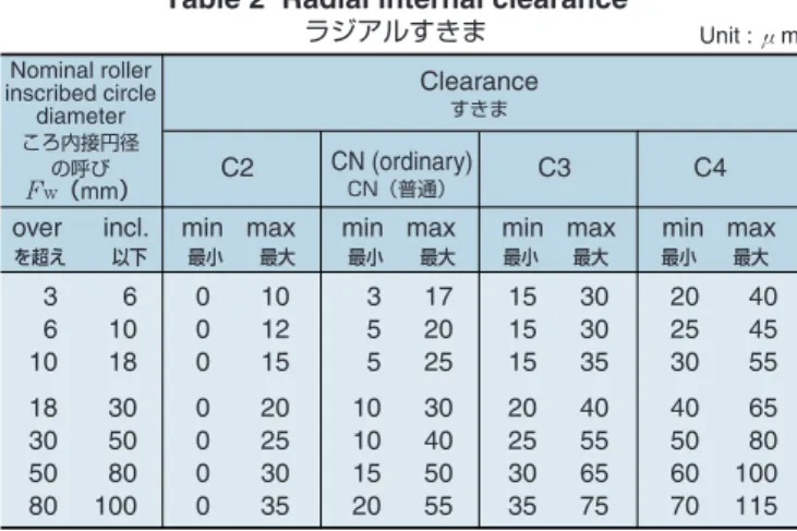
Table 2 Radial internal clearance ラジアルすきま Classification Metric series Inch series H7 F7
Tolerance class for mounting hole 区 分 穴の公差域クラス
メートル系
インチ系
注)衝撃荷重が作用する場合には,スタッドと穴とのすきまをでき るだけ小さくして組み立ててください。
Note) When a shock load is applied, make the clearance between the stud and hole as small as possible.
Clearance すきま
Unit : μm
C2 CN (ordinary)
CN(普通) C3 C4
over incl. min max min max min max min max
3 6 10 18 30 50 80 6 10 18 30 50 80 100 0 0 0 0 0 0 0 10 12 15 20 25 30 35 3 5 5 10 10 15 20 17 20 25 30 40 50 55 15 15 15 20 25 30 35 30 30 35 40 55 65 75 20 25 30 40 50 60 70 40 45 55 65 80 100 115 Nominal roller inscribed circle diameter ころ内接円径 の呼び Fw(mm) を超え 以下 最小 最大 最小 最大 最小 最大 最小 最大
軸受の精度
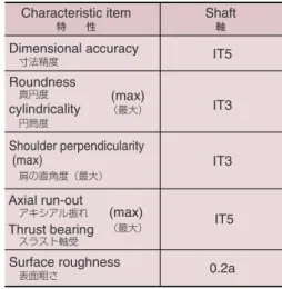
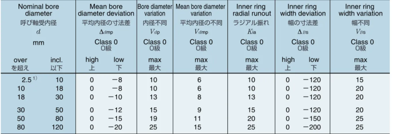
円筒面外径(D),外輪幅(C)の寸法精度,形状精度及び軸受 組立の回転精度は93ページの表12に示し,精度等級はJIS 0 級である。 球面外径(D),及びスタッド径(d1)の寸法精度は寸法表に示 している。はめあい及びラジアルすきま
スタッドを取付ける穴の推奨はめあいを表1に示す。 また,ラジアルすきまは表2に示す。Bearing accuracy
The dimensional accuracy and profile accuracy of the cylindrical roller outer diameter (D) ,the outer ring width (C), and the running accuracy of the bearing assembly are as shown in Tables 12 (page 93) The accuracy class conforms to JIS Class-0.
The dimensional accuracy of spherical outer diameter (D) and stud diameter (d1) are as shown in applicable
Dimension Tables.
Bearing fit and radial internal clearance
Table 1 shows the recommended fitting tolerance forthe stud mounting hole.
Table 2 shows the radial internal clearance.
Accuracy
/Lubrication and Method for Grease Replenishment
軸受の精度/潤滑と内部への供給・補給方法潤滑と内部への供給・補給方法
潤滑
合成ゴムシールを装着した形式(接尾記号LL)及び総ころ形式 には,リチウム石けん基のグリースが前もって封入され,−20 ∼+100℃の温度範囲で使用できる。 なお,常時0℃以下の場合には,低温特性に優れたグリース 封入品仕様を推奨しますのでNTN
へ御照会ください。 保持器付き形でシールなし品には,グリースは封入されてい ません。封入品が必要な場合はNTN
へ御照会ください。 なお,潤滑剤の漏れが少ない固形グリースを封入したNTN
ポ リルーブベアリングもありますので,NTN
へ御照会ください。 また,大気中での低発塵性が必要な場合には低発塵用グリー スを封入することもできますのでNTN
へ御照会ください。Table 3 Grease nipple dimensions グリースニップル寸法 d D L L1 Nominal nipple number Dimensions 寸 法 mm L L1 Dimensions 寸 法 mm d H R L B Nominal nipple number ニップル呼び番号 ニップル呼び番号
軸受の外輪外径面と軌道(トラック)間にも潤滑
が必要です。潤滑されていないと,軸受の損傷が
早期に発生する場合があります。
供給・補給方法
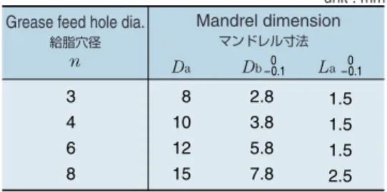
グリースガン等を用いてスタッドのフランジ端面,またはね じ側端面に取付けられたグリースニップルにより行う。給脂し ない側の給脂穴またはタップ穴はプラグ(専用プラグまたは六 角穴付きねじプラグ)により塞ぐ。 グリースニップル及びプラグはパッケージに同封されている ので,カムフォロアを組付ける前に取付ける。 グリースニップルには専用のものとJISで定められたものが あり,その寸法を表3に,適用軸受形式を表4に示す。 また,プラグにも専用の圧入タイプと六角穴付きねじプラグ があり,その寸法を表5-1,2に,適用軸受形式を表6に示す。 専用の圧入タイププラグの場合は,表7に示す寸法のマンド レルを用いて給脂穴に圧入する。Method for Grease Replenishment
Replenishment of grease can be performed by attaching a grease-gun to a grease nipple on the flange end face or threaded-side end face of the stud. Be sure to first plug the grease-feed hole or the tapped hole on the opposite side with a special-purpose plug or a threaded plug with hexagonal socket.A grease nipple and plug are enclosed in each cam follower package. Attach them to the cam follower before mounting unit.
Both special grease nipples and those specified in the JIS Standard are available. The dimensions thereof and the applicable bearing types are specified in Tables 3 and 4 respectively.
Furthermore, special press-fit type plugs and threaded plugs with hexagonal sockets are available. The
dimensions thereof and the applicable bearing types are specified in Tables 5-1, 5-2 and Table 6.
When using special-purpose press-fit plugs, press-fit into the grease feed hole using a mandrel as shown in
Table 7.
The outer ring outer surface of bearing and the track surface must both be lubricated. Failure to lubricate could result in premature bearing failure.
Lubrication and Method for Grease Replenishment
LubricationCam followers with synthetic rubber seals (LL suffix) and full-complement roller types are pre-filled with lithium soap base grease. They can be used in the operating temperature range of -20 to +100˚C.
Please contact NTN if a grease with better low-temperature characteristics is desired.
Unsealed cage-type cam followers are not
prelubricated. If a prelubricated type is needed, feel free to contact NTN.
Additionally, NTN Bearings with Solid Grease, which have solid lubricant with less leakage than conventional grease, are also available on request. Feel free to contact
Table 4 Grease nipple availability for various cam followers series グリースニップル適用軸受形式と寸法記号 NIP-B3 NIP-B4 NIP-B6 NIP-B8 NIP-X30 JIS A-M6F JIS A-PT1/8 ― 16∼26 30∼40 47∼90 ― ― ― ― 22∼26 30∼40 47∼90 ― ― ― 8.8-1 10∼18 20∼44 48∼96 ― ― ― ― 12∼18 20∼44 48∼96 ― ― ― ― ― 30∼40 47∼90 ― ― 100∼180 (Threaded side) (ねじ側) ― ― 30∼40 47∼90 ― ― 100∼180 ― ― ― ― 16∼26 30∼32 35∼90 ― ― ― ― 16∼26 30∼35 40∼90 ― ― ― ― ― 30∼35 40∼180 ― ― ― ― ― 30 35∼180 Nominal nipple number ニップル呼び番号
Cam follower series 適用軸受形式
KR,KRV
KR‥H,
KRV‥H CRV‥H CRV NUKR‥H NUKR KRT,KRVT NUKRT KRU,KRVU NUKRU
Table 6 Plug availability for various cam follower series プラグ適用軸受形式と寸法記号 SEN3 SEN4 SEN6 SEN8 M4X0.7X4R M6X0.75X6R PT1/8X7R ― 16∼26 30∼40 47∼90 ― ― ― ― 22∼26 30∼40 47∼90 ― ― ― 8.8-1 10∼18 20∼44 48∼96 ― ― ― ― 12∼18 20∼44 48∼96 ― ― ― ― ― 30∼40 47∼180 ― ― ― ― ― 30∼40 47∼90 ― ― 100∼180 ― ― ― ― 16∼26 30∼32 35∼90 ― ― ― ― 16∼26 30∼35 40∼90 ― ― ― ― ― 30∼35 40∼180 ― ― ― ― ― 30 35∼180 Plug プラグ
Cam follower series 適用軸受形式
KR,KRV KRKRV‥H,
‥H CRV CRV‥H NUKR NUKR‥H KRT,KRVT NUKRT KRU,KRVU NUKRU
専用プラグ 六角穴付きねじプラグ
プラグ寸法 プラグ寸法
Special-purpose plug
Threaded plug with hexagonal socket
Table 5-1 Plug dimensions Table 5-2 Plug dimensions
SEN 3 SEN 4 SEN 6 SEN 8 3 4 6 8 3 4 6 8 unit : mm unit : mm Nominal number D D H H M4X0.7X4R M6X0.75X6R PT1/8X7R M4X0.7 M6X0.75 PT1/8 4 6 7 2 3 5 Nominal number d H Width across flats h 二両幅 呼び番号 呼び番号 La n Db Da Plug プラグ圧入用マンドレル Grease feed hole dia.
給脂穴径 n Da Db La Mandrel dimension マンドレル寸法 3 8 2.8 1.5 0 –0.1 –0.10
Table 7 Mandrels used for press-fitting of plug
unit : mm
Lubrication and Method for Grease Replenishment
潤滑と内部への供給・補給方法
[a] JIS B 1181 3種の薄型 ナットをダブルナットと して用いる。
[b] 標準ナットに座金を 用いる。
[a] Use two JIS B 1181 Class-3 thin nuts as a double nut for tightening.
[b] Use a lock washer with standard nut.
e 側面高さ Face height 荷重 Loading 荷重 Loading Fig.2
Installation
(1) Make the face height at the cam follower mount greater than "e" dimension given in the applicable Dimension Table. (Fig.2)
Furthermore, make the chamfer of the stud mounting hole as small as possible (around 0.5×45˚) to bring the side face and housing into precise contact.
取付け関係
(1)カムフォロアの取付け部における側面高さは,寸法表に記 載の"e"寸法より大きくとる(図2)。スタッド取付け穴の 面取りは,なるべく小さくし(0.5X45°程度),側板の 側面を正確に当てるようにする。
(2) Don't hammer directly the cam follower rib. Doing so may cause damage to the rib and eventual bearing failure.
(2)カムフォロアのつば部を直接ハンマなどで叩かないこと。 つば部が割れたり,回転不良の原因となる。
Fig.4
Fig.5
(3) The oil hole position on the stud raceway surface is designated by the NTN mark stamped on the stud rib surface. Mount the stud so the oil hole is located opposite the load zone. (Fig. 4) If the oil hole is located within the load area, it may result in shorter life of the follower.
(3)スタッドの軌道面にある油穴位置は,スタッドのつば面の
NTN
マークで示しており,非負荷域(荷重を受けない側) に取付ける。(図4)油穴が負荷域にあると,短寿命の原因となる。
(4) In applications where the stud and nut may loosen due to a wide amplitude of vibration during operation,
NTN recommends the mounting methods illustrated in
Fig. 5. (4)特に振動の激しい使用条件で取付け用のねじの緩む恐れの ある場合は,図5のような方法がある。
Installation
取付け関係Cam Followers
Fig.6
(5) The stud is subjected to bending stress and tensile force arising from bearing load. Tighten the stud screws with tightening torque which does not exceed the torque value specified in applicable Dimension Table.
Overtightening could result in damage to the threaded portion.
(6) A hole is provided in the center of the stud as illustrated in Fig. 6. Use this hole for locking the follower in place or grease replenishment.
(5)スタッドは軸受荷重による曲げ応力及び引張力を受けるの で,ねじの締付トルクは寸法表の値を超えないように締付 ける。 締付トルクが大きすぎると,ねじ部が破断することがあ る。 (6)スタッド中央の軸心に直角に設けた穴は,図6のような回 り止め,またはグリースの補給用として用いる。
(7) For mounting and adjustment of eccentric stud type cam followers, follow the instructions below. 1. Insert the stud in the mounting hole so that the NTN
mark (showing oil hole position) is located opposite of the loaded area of the bearings as illustrated in Fig. 4. 2. Turn the stud using the recessed slot on the stud head
or the threaded plug with hexagonal socket to adjust the clearance with the mating contact surface. 3. After adjustment, tighten the stud nut to the tightening
torque described in the applicable Dimensions Table.
(7)スタッド偏心形カムフォロアの取付け調整は,次のように 行う。 1 荷重が,作用する方向に対し,スタッドを
NTN
マーク(油 穴位置)が図4の位置になるように取付け穴を挿入し,ナ ットを軽く締込む。この時スタッドは,回るようにしてお く。 2 スタッド頭部のドライバー溝又は,付属の六角穴付きねじ プラグをスタッドに取付けスタッドを回転させて,相手接 触面とのすきまを調整する。 3 調整が終わったら,スタッドが,回らないように,ナット を寸法表記載のトルクで締付ける。NTN
カムフォロアは,一般的に片持ちで取付ける
ため,継続使用によるはめあいのゆるみの影響で
不均一な荷重(片当り)が軸受に作用する場合が
あります。設備安定稼動のため,はめあいのゆる
みには十分な注意が必要です。
NTN cam follower are generally mounted by a stud supported on only one side. This cantilevered load arrangement can lead to an increase in bearing clearance over time due to wear from uneven load distribution within the bearing.
To ensure stability of equipment , check that the clearance between the stud and mounting hole is sufficiently small to prevent uneven loading.
Installation
取付け関係
カムフォロア・ローラフォロアのトラック負荷容量
トラック負荷容量は,硬度と材料の純引張応力における関係 で基準硬度(基準引張応力)を設定し,その応力とヘルツ応力 の関係から求めた。 基準硬度(引張応力)のとり方は各社で若干異なるが,ここ では,硬度一引張応力の関係として鉄鋼JISハンドブック巻末表 を用いた(JIS Z8413改訂案換算表による近似数値)。 基準硬度(引張応力)として HRC40ではσ=1 245MPa(127kgf/mm2)を採用した。〈トラック負荷容量補正係数〉
材料は,硬度の増加とともに引張応力が増大するが,それに 伴ってトラック負荷容量も増大する。この場合は表8に示すト ラック負荷容量補正係数をトラック負荷容量に乗じて求めるこ とができる。 注)ここで求めたトラック負荷容量は,純引張応力を基準として おり,許容ヘルツ応力ではない。一般に材料にクリープを 起こす応力(比応力)は引張応力より大きく,特に静的荷重 の場合,今回のトラック負荷容量は安全側の値となる。 例〕トラック負荷容量補正係数を用いてある硬さのトラック負荷 容量Tc'を求める場合 寸法表記載値のトラック負荷容量をTc,当該硬さにおける トラック負荷容量補正係数をGとすると,そのときのトラッ ク負荷容量Tc'は Tc'=G・Tc となる。 NATR15Xで硬度HRC50の場合 Tc= 11 900N(1 220kgf), G=1.987 ∴ Tc'=1.987×11 900N(1 220kgf) =23 645N(2 424kgf)Track Load Capacity of Cam Followers
and Roller Followers
The track load capacity is calculated by determining the standard hardness (standard tensile stress) from the relation between the hardness and pure tensile force on the material, and by the relation between the standard tensile stress and Hertz stress.
The method of determining the standard hardness (standard tensile stress) varies from manufacturer to manufacturer. NTN has chosen to use the hardness-tensile stress relation table at the end of the JIS Handbook for Steel (approximate values in the revised conversion table in JIS Z 8413).
For the standard hardness (tensile stress) of HRC40, we selected the following:
σ= 1245 MPa (127 kgf/mm2).
Correction factors for track load capacity
The greater the hardness of the track material, the greater the tensile stress of the track material, which results in a greater track load capacity. The true track load capacity is determined under this assumption by multiplying the track load capacity correction factor inTable 8 by the corresponding track load capacity in the
same table.
Note: The track load capacity determined by this method
is based on a pure tensile stress and is not an allowable Hertz stress. Generally, a stress (relative stress) that causes creep on a material is greater than a tensile stress. In the case of a static load in
particular, the track load capacity determined by the above-mentioned method can be considered to include a margin of safety.
Example: Determine a track load capacity Tc', at a given hardness by using a track load capacity correction factor.
The track load capacity Tc'can be determined by finding a track load capacity Tcin the dimension table and a track load capacity correction factor G in Table
8. The procedure is as follows:
Tc'= G×Tc
For the NATR15X type roller follower with hardness HRC50:
Tc= 11,900N(1,220kgf), G=1.987 ∴Tc'=1.987×11,900N(1,220kgf)
=23,645N(2,424kgf)
Track Load Capacity of Cam Followers and Roller Followers
カムフォロア・ローラフォロアのトラック負荷容量
Cam Followers
参考(トラック負荷容量 算出プロセス)σ
max=60.9σ
max= Beff TcΣρ μν 187 (Σρ)2T c 3 ¡外輪形状円筒の場合 ¡外輪形状球面の場合σ
max=60.9σ
max= Beff TcΣρ μν 187 (Σρ)2T c 3¡With a cylindrical outer ring
¡With a spherical outer ring
σmax=1 245MPa(127kgf/mm2) Tc :トラック負荷容量(N{kgf}) Σρ:曲率の和 Beff:有効接触長さ(mm) ここでは(外輪幅−2×チャンファ) μν:曲率で決まる係数 20 21 22 23 24 25 26 27 28 29 30 31 32 33 34 35 36 37 38 39 40 41 42 43 44 45 46 47 48 49 50 51 0.368 0.387 0.397 0.417 0.437 0.459 0.480 0.502 0.536 0.560 0.583 0.620 0.645 0.684 0.723 0.750 0.806 0.863 0.893 0.953 1.0 1.080 1.147 1.233 1.322 1.414 1.509 1.607 1.729 1.834 1.987 2.145 0.223 0.241 0.250 0.269 0.289 0.311 0.333 0.356 0.393 0.419 0.446 0.488 0.518 0.565 0.615 0.650 0.723 0.802 0.844 0.931 1.0 1.123 1.228 1.369 1.519 1.681 1.853 2.037 2.274 2.484 2.800 3.141 外径円筒 補正係数 Correction factor G {77} {79} {80} {82} {84} {86} {88} {90} {93} {95} {97} {100} {102} {105} {108} {110} {114} {118} {120} {124} {127} {132} {136} {141} {146} {151} {156} {161} {167} {172} {179} {186} 755 774 784 804 823 843 862 882 911 931 951 980 1 000 1 029 1 058 1 078 1 117 1 156 1 176 1 215 1 245 1 294 1 333 1 382 1 431 1 480 1 529 1 578 1 637 1 686 1 754 1 823 Hardness HRC 硬度 Tensile stress MPa{kgf/mm2}
引張応力 Cylindrical outer surface
外径球面 Spherical outer surface Table 8. Track Load Capacity Correction Factor
トラック負荷容量補正係数
Track Load Capacity of Cam Followers and Roller Followers
カムフォロア・ローラフォロアのトラック負荷容量
Track Load Capacity Calculation Process
σmax=1,245MPa(127kgf/mm2)
Tc :Track load capacity(N{kgf})
Σρ :Sum of curvatures
Beff :Effective contact length(mm)
that is, (outer ring width−chamfer×2) μν :Factor governed by curvature
外輪強度
一般的には通常使用荷重であれば外輪が破壊することはない が,衝撃荷重,重荷重使用時の検討を実施する場合の計算方法 を以下に示す。 それぞれの外輪形状を図7とし,下記の式により求める。こ の場合の外輪破壊強度は,ころのブリッジ状態の破壊強度をい う。 破 壊 応 力 の と り 方 と し て , 一 般 に は , 軸 受 鋼 の 場 合 , 1760MPa{180kgf/mm2}をとれるが,応力集中を考慮した 場合,及び経験から更に安全側の値(1170MPa{120kgf/mm2}) をとるのが望ましい。一般的には,通常使用荷重であれば外輪 が破壊することはないが,衝撃荷重及び重荷重が加わる場合に は外輪破壊強度をチェックする必要がある。 なお,通常使用の応力としては196MPA{20kgf/mm2} 以下であることが望ましい。 4π D−2h P=――――――×――――――――×I×σ 1+f(α) h(D−2h2)2 ここで (π−α)sinα−(1+cosα) f (α)=―――――――――――――――――― 2cosα π α=――(rad.) Z P:破壊荷重(N) I:外輪断面二次モーメント(mm4) Z:ころ数 σ=破壊応力(MPa) D,h,h2:図7参照(mm)とする。 h h h 2 h h h 2 Center of figure 図心 Center of figure 図心Outer Ring Strength
外輪強度
Cam Followers
Outer Ring Strength
The outer ring should not break under normal operating loads. When considering outer ring strength when the cam follower is used under an impact load or heavy load, use the following method for calculating the outer ring strength.
The forms of the outer ring are illustrated in Fig. 7. The outer ring strength is calculated with the expressions given below. The outer ring breaking strength is the breaking strength when the rollers are supported in a bridge configuration.
Generally, the breaking stress of bearing steel can be assumed to be 1760 MPa (180 kgf/mm2). However, in our
experience we have found it preferable to assume a breaking stress value with a safety margin [1170 MPa (120 kgf/mm2)] in order to reflect stress concentration.
The outer ring should not break under normal operating loads. However, if an impact load or heavy load is expected on the outer ring, it is necessary to check the breaking strength of the outer ring.
It is recommended to use 196MPa{20kgf/mm2}or
less for continuous use.
4π D−2h P=――――――×――――――――×I×σ 1+f(α) h(D−2h2)2 where (π−α)sinα−(1+cosα) f (α)=――――――――――――――――― 2cosα π α=――(rad.) Z P:Breaking load (N)
I:Outer ring cross-section secondary moment (mm4)
Z:Number of rollers
σ=Breaking stress (MPa)
Cam Followers
Cam Follower Stud Strength
カムフォロアのスタッド強度 Fr 軸断面 A R Shaft cross-sectionカムフォロアのスタッド強度
図8のように外輪中央に荷重Frが作用する場合,曲げモーメ ントFr・Rが生じ,スタッド表面には曲げ応力σ1(引張応力と 考える)が発生する。さらにスタッド自体は,機械本体にナッ トで締付けられて設置されるため,ねじ締付けによる引張応力 σ2も生じる。この引張応力の和(σ1+σ2)と,材料の許容応 力σとの比較からスタッド強度の検討ができる。 σ1+σ2<σ Fr・R Fr:最大ラジアル荷重 σ1=―――― Z Z:点Aを通る軸断面係数 σ2≒98MPa{10kgf/mm2} 寸法表に記している締付け最大トルクによる引 張応力 σ:材料の許容応力 材料の繰り返し曲げ試験の結果から次の値をとる。 静的曲げ応力を受ける場合 σ=1372MPa{140kgf/mm2} 繰り返し曲げ応力を受ける場合(片振り) σ=784MPa{80kgf/mm2} 繰り返し曲げ応力を受ける場合(両振り) σ=392MPa{40kgf/mm2} したがって Z Fr<―――(σ-σ2) RCam Follower Stud Strength
If a load Fr is exerted on the midpoint of the outer ring as illustrated in Fig. 8, a bending moment Frx Roccurs,
and a bending stress
σ
1(considered to be a tensilestress) occurs on the stud surface. Furthermore, since the stud itself is mounted to the machine side with a nut, a tensile stress
σ
2resulting from a thread tightening forcealso occurs. The stud strength can be evaluated by comparing the sum of the tensile stresses (
σ
1+σ
2) withthe allowable stress s of the stud material.
σ
1+σ2<σFr・R
σ
1=――――Z
Fr:Max. radial load
Z :Shaft cross-section intersecting point A factor
σ
2≒98MPa{10kgf/mm2}Tensile stress resulting from max. tightening torque specified in dimension table
σ
:Allowable stress of the materialThe following value is determined from the results of the flex test:
Allowable stress for application of static bending stress:
σ
=1372MPa{140kgf/mm2}Allowable stress for application of repeated bending stress (in one direction):
σ
=784MPa{80kgf/mm2}Allowable stress for application of repeated bending stress (in both directions):
σ
=392MPa{40kgf/mm2}therefore
Z
Fr<―――(σ-σ2) R
Miniature Cam Followers
ミニアチュアカムフォロア
KRM・
・・
・XH type
(with cage)
KRMV・
・・
・XH type
(Full-complement roller type)
ミリ系 インチ系 保持器付 総ころ シールなし シール付 六角穴 タップ穴 ドライバ溝 KRM・・XH形(保持器付) KRMV・・XH形(総ころ形)
Note: 1. JIS Class 0 is the dimensional tolerance.
注1)許容差はJIS 0級である。 4 KRM4XT2H/3AS ― 1.5 2 1.8 3.5 6.5 3 M1.4×0.3 1.5 0.7 3.8 0.9 ― KRMV4XH/3AS 1.5 2 1.8 3.5 6.5 3 M1.4×0.3 1.5 0.7 3.8 0.9 4.5 KRM4.5XT2H/3AS ― 2 2.5 2.25 4 8 4 M2 ×0.4 2 0.7 4.3 0.9 ― KRMV4.5XH/3AS 2 2.5 2.25 4 8 4 M2 ×0.4 2 0.7 4.3 0.9 5 KRM5XT2H/3AS ― 2.5 3 2.7 4.5 9.5 5 M2.5×0.45 2.5 0.7 4.8 0.9 ― KRMV5XH/3AS 2.5 3 2.7 4.5 9.5 5 M2.5×0.45 2.5 0.7 4.8 0.9 6 KRM6XT2H/3AS ― 3 4 3.4 5.5 11.5 6 M3 ×0.5 3 0.7 5.8 1.3 ― KRMV6XH/3AS 3 4 3.4 5.5 11.5 6 M3 ×0.5 3 0.7 5.8 1.3 8 KRM8XT2H/3AS ― 4 5 4.5 7 15 8 M4 ×0.7 4 1 7.7 1.5 ― KRMV8XH/3AS 4 5 4.5 7 15 8 M4 ×0.7 4 1 7.7 1.5 10 KRM10XT2H/3AS ― 5 6 5.9 8 18 10 M5 ×0.8 5 1 9.6 2 ― KRMV10XH/3AS 5 6 5.9 8 18 10 M5 ×0.8 5 1 9.6 2 12 KRM12XT2H/3AS ― 6 7 6.7 9.5 21.5 12 M6 ×1 6 1.2 11.6 2.5 ― KRMV12XH/3AS 6 7 6.7 9.5 21.5 12 M6 ×1 6 1.2 11.6 2.5
Cam Follower number
呼び番号 With cage 保持器付き Full-complement roller 総ころ OD1) 外径 mm D d 1 C F B B1 B2 G G1 C1 e h Dimensions 寸法 mm 0 −0.006 0 −0.006 0 −0.006 0 −0.006 0 −0.008 0 −0.008 0 −0.008
Metric series Inch series With cage Full-complement roller
Without seal With seal Hexagonal socket Tapped hole Slot for screwdriver
φD φF φd1 φe h C B B2 B1 C1 G1 G
KRM・
・・
・XH type (with cage)
KRM‥XH形(保持器付)0.0003 1.5 0.0004 0.0005 2 0.0006 0.0007 2.5 0.0009 0.0013 3 0.0014 0.0029 4 0.0030 0.0055 5 0.0059 0.0093 6 0.0080 Stud dia. スタッド径 mm Maximum tightening torque 締付最大トルク N・m kgf・m Mass 質量 kg (approx.) (参考) Cr Cor Track load capacity トラック負荷容量 N kgf 222 23 505 51 305 31 695 71 445 45 905 92 645 66 1 280 130 1 120 114 2 120 216 1 570 160 2 820 288 2 160 220 4 150 425 138 14 480 49 216 22 765 78 370 37 1 110 114 630 63 1 840 187 1 120 114 3 050 310 1 860 189 4 800 490 2 300 237 6 450 655 147 15 216 22 294 30 480 49 785 80 1 190 121 1 640 167 0.1 0.01 0.1 0.01 0.3 0.03 0.5 0.05 1 0.1 2 0.2 3 0.3 B1 C1 G1 φD φd1 φe φF h C B B2 G
KRMV・
・・
・XH type (Full-complement roller type)
KRMV‥XH形(総ころ形)N
kgf
Basic load ratings dynamic static
基本動 定格荷重
基本静 定格荷重
Cam Followers with Cage
保持器付カムフォロア
KR・
・・
・H type
KR・
・・
・XH type
KR・
・・
・LLH type
KR・
・・
・XLLH type
hMetric series Inch series With cage Full-complement roller
Without seal With seal Hexagonal socket Tapped hole Slot for screwdriver
ミリ系 インチ系
保持器付 総ころ
シールなし シール付
六角穴 タップ穴 ドライバ溝
10 KR10T2H/3AS KR10XT2H/3AS KR10T2LLH/3AS KR10XT2LLH/3AS 3 7 4 8 17 9 M3×0.5
12 KR12T2H/3AS KR12XT2H/3AS KR12T2LLH/3AS KR12XT2LLH/3AS 4 8 4.8 9 20 11 M4×0.7
13 KR13T2H/3AS KR13XT2H/3AS KR13T2LLH/3AS KR13XT2LLH/3AS 5 9 5.75 10 23 13 M5×0.8
16 KR16H/3AS KR16XH/3AS KR16LLH/3AS KR16XLLH/3AS 6 11 8 12 28 16 M6×1
19 KR19H/3AS KR19XH/3AS KR19LLH/3AS KR19XLLH/3AS 8 11 10 12 32 20 M8×1.25
22 KR22H KR22XH KR22LLH/3AS KR22XLLH/3AS 10 12 12 13 36 23 M10×1.25 26 KR26H KR26XH KR26LLH/3AS KR26XLLH/3AS 10 12 12 13 36 23 M10×1.25 30 KR30H KR30XH KR30LLH/3AS KR30XLLH/3AS 12 14 15 15 40 25 M12×1.5 32 KR32H KR32XH KR32LLH/3AS KR32XLLH/3AS 12 14 15 15 40 25 M12×1.5 35 KR35H KR35XH KR35LLH/3AS KR35XLLH/3AS 16 18 18 19.5 52 32.5 M16×1.5 40 KR40H KR40XH KR40LLH/3AS KR40XLLH/3AS 18 20 22 21.5 58 36.5 M18×1.5 47 KR47H KR47XH KR47LLH/3AS KR47XLLH/3AS 20 24 25 25.5 66 40.5 M20×1.5 52 KR52H KR52XH KR52LLH/3AS KR52XLLH/3AS 20 24 25 25.5 66 40.5 M20×1.5 62 KR62H KR62XH KR62LLH/3AS KR62XLLH/3AS 24 29 30 30.5 80 49.5 M24×1.5 72 KR72H KR72XH KR72LLH/3AS KR72XLLH/3AS 24 29 30 30.5 80 49.5 M24×1.5 80 KR80H KR80XH KR80LLH/3AS KR80XLLH/3AS 30 35 38 37 100 63 M30×1.5 85 KR85H KR85XH KR85LLH/3AS KR85XLLH/3AS 30 35 38 37 100 63 M30×1.5
Cam Follower number 2) 呼び番号
Without seal
シールなし
With seal
シール有り
Spherical outer rings
球面外輪
Cylindrical outer rings
円筒外輪 OD1) 外径 mm D 0
−0.05 Spherical outer rings球面外輪
Cylindrical outer rings
円筒外輪 d1 C F B B1 B2 G Dimensions 寸法 mm 0 −0.010 0 −0.012 0 −0.012 0 −0.012 0 −0.015 0 −0.015 0 −0.015 0 −0.018 0 −0.018 0 −0.018 0 −0.018 0 −0.021 0 −0.021 0 −0.021 0 −0.021 0 −0.021 0 −0.021
KR・
・・
・H type (with cage)
KR‥H形(保持器付) KR‥H形KR‥XH形 KR‥LLH形 KR‥XLLH形
Note: The boundary dimensions of grease nipples and plugs are listed in Table 3 on page 9 and Table 5 on page 10.
※グリースニップル及びプラグの主要寸法は9ページ表3,10ページ表5に示す。 NIP-B6 SEN6 1M12 Accessories / 付属部品 10∼19 22∼26 30∼40 47∼90 ― NIP-B4 NIP-B6 NIP-B8 ― SEN4 SEN6 SEN8 1M3×0.5∼1M8×1.25 1M10×1.25 1M12×1.5∼1M18×1.5 1M20×1.5∼1M30×1.5 Applicable bearing number 適用軸受 呼び番号 Grease nipple number グリースニップル 呼び番号 Plug number プラグ 呼び番号
Applicable hexagonal nut
適用六角ナット 5 ― 0.5 ― ― 7 2.5 ※27 000 ※40 000 0.005 3 6 ― 0.5 ― ― 8.5 2.5 ※25 000 ※36 000 0.008 4 7.5 ― 0.5 ― ― 9.5 3 ※23 000 ※33 000 0.010 5 8 ― 0.6 ― ― 12 3 ※19 000 ※25 000 0.019 6 10 ― 0.6 ― ― 14 4 ※15 000 ※20 000 0.031 8 12 ― 0.6 4 ― 17 4 ※12 000 ※16 000 0.046 10 12 ― 0.6 4 ― 17 4 ※12 000 ※16 000 0.059 10 13 6 0.6 6 3 23 6 10 000 ※13 000 0.087 12 13 6 0.6 6 3 23 6 10 000 ※13 000 0.097 12 17 8 0.8 6 3 27 6 8 000 ※11 000 0.169 16 19 8 0.8 6 3 32 6 7 000 9 000 0.248 18 21 9 0.8 8 4 37 8 6 000 8 000 0.386 20 21 9 0.8 8 4 37 8 6 000 8 000 0.461 20 25 11 0.8 8 4 44 8 5 000 6 500 0.790 24 25 11 0.8 8 4 44 8 5 000 6 500 1.04 24 32 15 1 8 4 53 8 4 000 5 500 1.55 30 Dimensions 寸法 mm Stud dia. スタッド径 mm Maximum tightening torque 締付最大トルク N・m kgf・m Mass 質量 kg (approx.) (参考) G1 B3 C1 n a h Cr Cor Spherical outer ring 球面外輪 Cylindrical outer ring 円筒外輪 Grease lubrication グリース潤滑 Oil lubrication 油潤滑 e Limiting speed 許容回転速度 r/min 1 640 168 1 270 130 560 57 1 360 139 0.5 0.05 2 170 221 1 690 172 725 74 1 790 183 1 0.1 2 650 270 2 260 231 805 82 2 220 226 2 0.2 4 050 415 4 200 430 1 080 110 3 400 350 3 0.3 4 750 480 5 400 555 1 380 141 4 050 415 8 0.8 5 300 540 6 650 680 1 690 172 5 150 525 14 1.4 5 300 540 6 650 680 2 120 216 6 100 620 14 1.4 7 850 800 9 650 985 2 620 267 7 700 785 20 2 7 850 800 9 650 985 2 860 291 8 200 835 20 2 12 200 1 240 17 900 1 830 3 200 325 11 900 1 220 52 5.3 14 000 1 430 22 800 2 330 3 850 390 14 500 1 480 76 7.8 20 700 2 110 33 500 3 450 4 700 480 21 000 2 150 20 700 2 110 33 500 3 450 5 550 565 23 300 2 370 28 900 2 950 55 000 5 600 6 950 710 34 500 3 500 98 10 98 10 178 18 28 900 2 950 55 000 5 600 8 050 820 38 500 3 900 178 18 45 000 4 600 88 500 9 050 9 800 1 000 53 000 5 400 360 37
KR・
・・
・LLH type (with cage, sealed)
KR‥LLH形(保持器付シール形)
Track load capacity
トラック負荷容量 N
kgf
Basic load ratings dynamic static N kgf 基本動 定格荷重 基本静 定格荷重
Cam Followers with Cage
保持器付カムフォロア
KR type
KR・
・・
・X type
KR・
・・
・LL type
KR・
・・
・XLL type
KR形 KR‥X形 KR‥LL形 KR‥XLL形Notes:1. JIS Class 0 is the dimensional tolerance of the outside diameter D of the outer rings of the KR・・X and KR・・XLL types whose outside surface form is cylindrical. 2. The grease replenishment port is situated only in the front (in the left side face in the diagram above).
注1)外径面が円筒であるKR‥X形,KR‥XLL形の外輪外径 D の許容差はJIS 0級である。 2)グリースの補給穴は正面(上図左側面)にだけ設けている。 16 KR16 KR16X KR16LL/3AS KR16XLL/3AS 6 11 8 12 28 16 M6×1 19 KR19 KR19X KR19LL/3AS KR19XLL/3AS 8 11 10 12 32 20 M8×1.25 22 KR22 KR22X KR22LL/3AS KR22XLL/3AS 10 12 12 13 36 23 M10×1.25 26 KR26 KR26X KR26LL/3AS KR26XLL/3AS 10 12 12 13 36 23 M10×1.25 30 KR30 KR30X KR30LL/3AS KR30XLL/3AS 12 14 15 15 40 25 M12×1.5 32 KR32 KR32X KR32LL/3AS KR32XLL/3AS 12 14 15 15 40 25 M12×1.5 35 KR35 KR35X KR35LL/3AS KR35XLL/3AS 16 18 18 19.5 52 32.5 M16×1.5 40 KR40 KR40X KR40LL/3AS KR40XLL/3AS 18 20 22 21.5 58 36.5 M18×1.5 47 KR47 KR47X KR47LL/3AS KR47XLL/3AS 20 24 25 25.5 66 40.5 M20×1.5 52 KR52 KR52X KR52LL/3AS KR52XLL/3AS 20 24 25 25.5 66 40.5 M20×1.5 62 KR62 KR62X KR62LL/3AS KR62XLL/3AS 24 29 30 30.5 80 49.5 M24×1.5 72 KR72 KR72X KR72LL/3AS KR72XLL/3AS 24 29 30 30.5 80 49.5 M24×1.5 80 KR80 KR80X KR80LL/3AS KR80XLL/3AS 30 35 38 37 100 63 M30×1.5 85 KR85 KR85X KR85LL/3AS KR85XLL/3AS 30 35 38 37 100 63 M30×1.5 90 KR90 KR90X KR90LL/3AS KR90XLL/3AS 30 35 38 37 100 63 M30×1.5 d1 C F B B1 B2 G 0 −0.012 0 −0.015 0 −0.015 0 −0.015 0 −0.018 0 −0.018 0 −0.018 0 −0.018 0 −0.021 0 −0.021 0 −0.021 0 −0.021 0 −0.021 0 −0.021 0 −0.021
KR type (with cage)
KR形(保持器付)
Metric series Inch series With cage Full-complement roller
Without seal With seal Hexagonal socket Tapped hole Slot for screwdriver
ミリ系 インチ系
保持器付 総ころ
シールなし シール付
六角穴 タップ穴 ドライバ溝
Cam Follower number
呼び番号
Without seal
シールなし
With seal
シール有り
Spherical outer rings
球面外輪
Cylindrical outer rings
円筒外輪 OD1) 外径 mm D 0
−0.05 Spherical outer rings球面外輪
Cylindrical outer rings
円筒外輪
Dimensions
寸法 mm
Accessories / 付属部品 16∼26 30∼40 47∼90 NIP-B4 NIP-B6 NIP-B8 SEN4 SEN6 SEN8 1M 6×1 ∼1M10×1.25 1M12×1.5∼1M18×1.5 1M20×1.5∼1M30×1.5 Applicable bearing number 適用軸受 呼び番号 Grease nipple number グリースニップル 呼び番号 Plug number プラグ 呼び番号
Applicable hexagonal nut
適用六角ナット
Note: The boundary dimensions of grease nipples and plugs are listed in Table 3 on page 9 and Table 5 on page 10.
※グリースニップル及びプラグの主要寸法は9ページ表3,10ページ表5に示す。
NIP-B6 SEN6 1M12
Note: The limiting speed of KR・・LL and KR・・XLL types incorporating a seal (those marked with an asterisk) is approximately 10,000 rpm.
備考 ※印シール有りKR‥LL形,KR‥XLL形の許容回転速度はおおよそ10 000r/minである。 8 ― 0.6 42) ― 12 ※19 000 ※25 000 0.019 6 10 ― 0.6 42) ― 14 ※15 000 ※20 000 0.031 8 12 ― 0.6 4 ― 17 ※12 000 ※16 000 0.046 10 12 ― 0.6 4 ― 17 ※12 000 ※16 000 0.059 10 13 6 0.6 6 3 23 10 000 ※13 000 0.087 12 13 6 0.6 6 3 23 10 000 ※13 000 0.097 12 17 8 0.8 6 3 27 8 000 ※11 000 0.169 16 19 8 0.8 6 3 32 7 000 9 000 0.248 18 21 9 0.8 8 4 37 6 000 8 000 0.386 20 21 9 0.8 8 4 37 6 000 8 000 0.461 20 25 11 0.8 8 4 44 5 000 6 500 0.790 24 25 11 0.8 8 4 44 5 000 6 500 1.04 24 32 15 1 8 4 53 4 000 5 500 1.55 30 32 15 1 8 4 53 4 000 5 500 1.74 30 32 15 1 8 4 53 4 000 5 500 1.95 30 G1 B3 C1 n a Cr Cor e 4 050 415 4 200 430 1 080 110 3 400 350 3 0.3 4 750 480 5 400 555 1 380 141 4 050 415 8 0.8 5 300 540 6 650 680 1 690 172 5 150 525 14 1.4 5 300 540 6 650 680 2 120 216 6 100 620 14 1.4 7 850 800 9 650 985 2 620 267 7 700 785 20 2 7 850 800 9 650 985 2 860 291 8 200 835 20 2 12 200 1 240 17 900 1 830 3 200 325 11 900 1 220 52 5.3 14 000 1 430 22 800 2 330 3 850 390 14 500 1 480 76 7.8 20 700 2 110 33 500 3 450 4 700 480 21 000 2 150 98 10 20 700 2 110 33 500 3 450 5 550 565 23 300 2 370 98 10 28 900 2 950 55 000 5 600 6 950 710 34 500 3 500 178 18 28 900 2 950 55 000 5 600 8 050 820 38 500 3 900 45 000 4 600 88 500 9 050 9 800 1 000 53 000 5 400 45 000 4 600 88 500 9 050 10 400 1 060 56 000 5 750 178 18 360 37 360 37 45 000 4 600 88 500 9 050 11 400 1 160 59 000 6 100 360 37
KR・
・・
・LL type (with cage, sealed)
KR‥LL形(保持器付シール形) Dimensions 寸法 mm Stud dia. スタッド径 mm Maximum tightening torque 締付最大トルク N・m kgf・m Mass 質量 kg (approx.) (参考) Spherical outer ring 球面外輪 Cylindrical outer ring 円筒外輪 Grease lubrication グリース潤滑 Oil lubrication 油潤滑
Track load capacity
トラック負荷容量 N kgf Limiting speed 許容回転速度 r/min
Basic load ratings dynamic static N kgf 基本動 定格荷重 基本静 定格荷重
Full-Complement Roller-Type Cam Followers
総ころ形カムフォロア
KRV・
・・
・H type
KRV・
・・
・XH type
KRV・
・・
・LLH type
KRV・
・・
・XLLH type
h KRV‥H形 KRV‥XH形 KRV‥LLH形 KRV‥XLLH形10 KRV10H/3AS KRV10XH/3AS KRV10LLH/3AS KRV10XLLH/3AS 3 7 4 8 17 9 M3×0.5
12 KRV12H/3AS KRV12XH/3AS KRV12LLH/3AS KRV12XLLH/3AS 4 8 4.8 9 20 11 M4×0.7
13 KRV13H/3AS KRV13XH/3AS KRV13LLH/3AS KRV13XLLH/3AS 5 9 5.75 10 23 13 M5×0.8
16 KRV16H/3AS KRV16XH/3AS KRV16LLH/3AS KRV16XLLH/3AS 6 11 8 12 28 16 M6×1
19 KRV19H/3AS KRV19XH/3AS KRV19LLH/3AS KRV19XLLH/3AS 8 11 10 12 32 20 M8×1.25
22 KRV22H/3AS KRV22XH/3AS KRV22LLH/3AS KRV22XLLH/3AS 10 12 12 13 36 23 M10×1.25
26 KRV26H/3AS KRV26XH/3AS KRV26LLH/3AS KRV26XLLH/3AS 10 12 12 13 36 23 M10×1.25
30 KRV30H/3AS KRV30XH/3AS KRV30LLH/3AS KRV30XLLH/3AS 12 14 15 15 40 25 M12×1.5
32 KRV32H/3AS KRV32XH/3AS KRV32LLH/3AS KRV32XLLH/3AS 12 14 15 15 40 25 M12×1.5
35 KRV35H/3AS KRV35XH/3AS KRV35LLH/3AS KRV35XLLH/3AS 16 18 18 19.5 52 32.5 M16×1.5
40 KRV40H/3AS KRV40XH/3AS KRV40LLH/3AS KRV40XLLH/3AS 18 20 22 21.5 58 36.5 M18×1.5
47 KRV47H/3AS KRV47XH/3AS KRV47LLH/3AS KRV47XLLH/3AS 20 24 25 25.5 66 40.5 M20×1.5
52 KRV52H/3AS KRV52XH/3AS KRV52LLH/3AS KRV52XLLH/3AS 20 24 25 25.5 66 40.5 M20×1.5
62 KRV62H/3AS KRV62XH/3AS KRV62LLH/3AS KRV62XLLH/3AS 24 29 30 30.5 80 49.5 M24×1.5
72 KRV72H/3AS KRV72XH/3AS KRV72LLH/3AS KRV72XLLH/3AS 24 29 30 30.5 80 49.5 M24×1.5
80 KRV80H/3AS KRV80XH/3AS KRV80LLH/3AS KRV80XLLH/3AS 30 35 38 37 100 63 M30×1.5
90 KRV90H/3AS KRV90XH/3AS KRV90LLH/3AS KRV90XLLH/3AS 30 35 38 37 100 63 M30×1.5
d1 C F B B1 B2 G 0 −0.010 0 −0.012 0 −0.012 0 −0.012 0 −0.015 0 −0.015 0 −0.015 0 −0.018 0 −0.018 0 −0.018 0 −0.018 0 −0.021 0 −0.021 0 −0.021 0 −0.021 0 −0.021 0 −0.021
KRV・
・・
・H type (Full-complement roller type)
KRV‥H形(総ころ形)
Metric series Inch series With cage Full-complement roller
Without seal With seal Hexagonal socket Tapped hole Slot for screwdriver
ミリ系 インチ系
保持器付 総ころ
シールなし シール付
六角穴 タップ穴 ドライバ溝
Cam Follower number
呼び番号
Without seal
シールなし
With seal
シール有り
Spherical outer rings
球面外輪
Cylindrical outer rings
円筒外輪 OD1) 外径 mm D 0
−0.05 Spherical outer rings球面外輪
Cylindrical outer rings
円筒外輪
Dimensions
寸法 mm
Note: The boundary dimensions of grease nipples and plugs are listed in Table 3 on page 9 and Table 5 on page 10.
※グリースニップル及びプラグの主要寸法は9ページ表3,10ページ表5に示す。 NIP-B6 SEN6 1M12 Accessories / 付属部品 10∼19 22∼26 30∼40 47∼90 ― NIP-B4 NIP-B6 NIP-B8 ― SEN4 SEN6 SEN8 1M3×0.5∼1M8×1.25 1M10×1.25 1M12×1.5∼1M18×1.5 1M20×1.5∼1M30×1.5 Applicable bearing number 適用軸受 呼び番号 Grease nipple number グリースニップル 呼び番号 Plug number プラグ 呼び番号
Applicable hexagonal nut
適用六角ナット 5 ― 0.5 ― ― 7 2.5 ※25 000 ※32 000 0.005 3 6 ― 0.5 ― ― 8.5 2.5 ※20 000 ※27 000 0.008 4 7.5 ― 0.5 ― ― 9.5 3 ※17 000 ※22 000 0.011 5 8 ― 0.6 ― ― 12 3 ※13 000 ※16 000 0.020 6 10 ― 0.6 ― ― 14 4 10 000 ※13 000 0.032 8 12 ― 0.6 4 ― 17 4 8 500 ※11 000 0.047 10 12 ― 0.6 4 ― 17 4 8 500 ※11 000 0.061 10 13 6 0.6 6 3 23 6 6 500 8 500 0.089 12 13 6 0.6 6 3 23 6 6 500 8 500 0.100 12 17 8 0.8 6 3 27 6 5 500 7 000 0.172 16 19 8 0.8 6 3 32 6 4 500 6 000 0.252 18 21 9 0.8 8 4 37 8 4 000 5 000 0.392 20 21 9 0.8 8 4 37 8 4 000 5 000 0.465 20 25 11 0.8 8 4 44 8 3 300 4 500 0.800 24 25 11 0.8 8 4 44 8 3 300 4 500 1.05 24 32 15 1 8 4 53 8 2 600 3 500 1.56 30 G1 B3 C1 n a h Cr Cor e 2 500 255 2 610 267 560 57 1 360 139 0.5 0.05 3 500 360 3 800 385 725 74 1 790 183 1 0.1 4 500 455 5 350 545 805 82 2 220 226 2 0.2 6 500 665 9 350 955 1 080 110 3 400 350 3 0.3 7 450 760 11 700 1 190 1 380 141 4 050 415 8 0.8 8 200 840 14 000 1 420 1 690 172 5 150 525 14 1.4 8 200 840 14 000 1 420 2 120 216 6 100 620 14 1.4 12 000 1 230 20 300 2 070 2 620 267 7 700 785 20 2 12 000 1 230 20 300 2 070 2 860 291 8 200 835 20 2 17 600 1 790 34 000 3 500 3 200 325 11 900 1 220 52 5.3 19 400 1 980 42 000 4 250 3 850 390 14 500 1 480 76 7.8 28 800 2 940 61 000 6 250 4 700 480 21 000 2 150 28 800 2 940 61 000 6 250 5 550 565 23 300 2 370 39 500 4 000 98 500 10 000 6 950 710 34 500 3 500 98 10 98 10 178 18 39 500 4 000 98 500 10 000 8 050 820 38 500 3 900 178 18 58 000 5 900 147 000 15 000 9 800 1 000 53 000 5 400 360 37
KRV・
・・
・LLH type
(Full-complement roller type, with seal)
KRV‥LLH形(総ころシール形) Dimensions 寸法 mm Stud dia. スタッド径 mm Maximum tightening torque 締付最大トルク N・m kgf・m Mass 質量 kg (approx.) (参考) Spherical outer ring 球面外輪 Cylindrical outer ring 円筒外輪 Grease lubrication グリース潤滑 Oil lubrication 油潤滑
Track load capacity
トラック負荷容量 N kgf Limiting speed 許容回転速度 r/min
Basic load ratings dynamic static N kgf 基本動 定格荷重 基本静 定格荷重