Neutron-neutron correlation
in Borromean nucleus
11
Li
via the (p
, pn) reaction
*.
..
,
(p
, pn)
反応を通じた
ボロミアン核における
中性子相関の研究
+/
//
-平成
27
年
12
月博士(理学)申請
東京大学大学院理学系研究科
物理学専攻
久保田 悠樹
Neutron-neutron correlation in light neutron-rich Borromean nuclei has attracted much attention. In particular, it has long been presumed that the neutron-neutron correlation caused by the
dineutron (dineutron correlation) is a key ingredient to understand the binding mechanism and
the exotic structures of these nuclei.
In the present work, the neutron momentum distribution in 11Li was determined by em-ploying the quasi-free (p, pn) reaction at 246 MeV/nucleon. We employed a new method of kinematically complete measurement, which enabled us to extract the ground-state neutron-neutron correlation as well as to investigate the structure of the9Li+ n subsystem through the momentum measurement and the invariant mass spectroscopy, respectively.
The experiment was performed at the Radioactive Isotope Beam Factory (RIBF) in RIKEN. The MINOS device was used so as to achieve high luminosity. The recoil particle detectors RPD and WINDS, both constructed for this study, were used for the (p, pn) measurement. The SAMURAI spectrometer having a large acceptance contributed to the kinematically complete measurement.
The spectroscopy of the10Li provided strong constraints on the interaction between a neutron and a9Li nucleus. The existence of the s-wave virtual state and of the p-wave resonance was confirmed and their resonance parameters were determined. Moreover, the d-wave resonance was newly found at Er = 5.52 ± 0.04 MeV with a decay width of Γ = 0.72 ± 0.10 MeV.
The fraction of each multipole up to d-wave was determined from the neutron momentum distribution: 35± 4%, 59 ± 1%, and 6 ± 4% for the two-neutron configurations (s1/2)2, (p1/2)2, and (d5/2)2or (d3/2)2, respectively. This result indicates the dineutron correlation can be weaker than previously reported.
It was suggested experimentally for the first time that the dineutron correlation in 11Li is developed in the surface region. The expectation value of the opening angle between the two neutrons was determined as ⟨θYx⟩ = 85 ± 10 degrees. It also supports the weaker dineutron correlation than expected from the previous works.
1 Introduction 1
1.1 Borromean nucleus11Li . . . 2
1.2 Studies on11Li through nuclear reactions . . . 4
1.2.1 Opening angle as a measure of dineutron correlation . . . 5
1.2.2 B(E1) measurement . . . . 5
1.2.3 Momentum measurement . . . 7
1.2.4 Summary of knowledge . . . 8
1.3 Thesis objectives . . . 9
2 Experimental approach 11 2.1 Our approach to neutron-neutron correlation . . . 11
2.2 The quasi-free (p, pn) reaction followed by the neutron emission . . . 12
2.2.1 Simple reaction mechanism: quasi-free knockout . . . 12
2.2.2 Minimization of the FSIs . . . 15
2.2.3 Kinematically complete measurement . . . 16
2.2.4 Transparency . . . 16
2.3 Definition of coordinates . . . 16
2.4 Experimental requirements . . . 19
3 Experiment 21 3.1 RIKEN RI Beam Factory . . . 21
3.2 Acceleration of a48Ca primary beam . . . 22
3.3 Production of a11Li secondary beam . . . 23
3.3.1 Fragment separator BigRIPS . . . 23
3.3.2 Beam line detectors of BigRIPS . . . 24
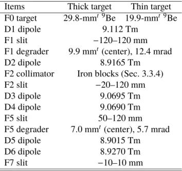
3.3.3 Setting parameters of BigRIPS . . . 25
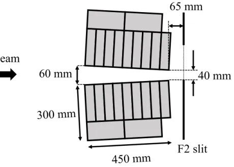
3.3.4 Reduction of triton contaminant . . . 26
3.3.5 Beam intensity and purity . . . 27
3.4 Beam transport to a secondary target . . . 28
3.5 SAMURAI setup . . . 31 iv
3.6 Magnetic spectrometer SAMURAI . . . 34
3.6.1 SAMURAI magnet . . . 36
3.6.2 Configuration of detectors . . . 36
3.6.3 Plastic scintillators SBTs . . . 38
3.6.4 Beam drift chambers BDCs . . . 38
3.6.5 Active collimator ACOL and beam veto BV . . . 39
3.6.6 Forward drift chambers FDC1 and FDC2 . . . 40
3.6.7 Hodoscopes HODF and HODP . . . 41
3.7 MINOS . . . 42
3.7.1 Liquid hydrogen target . . . 43
3.7.2 MINOS TPC . . . 45
3.8 Recoil proton detector RPD . . . 45
3.8.1 Multi-wire drift chamber RPDC . . . 48
3.8.2 Plastic scintillator hodoscope RPTOF . . . 48
3.9 Knocked-out neutron detector array WINDS . . . 49
3.10 Gamma-ray detector array DALI2 . . . 51
3.11 Neutron detector array NEBULA . . . 53
3.12 Electronic circuits and data acquisition . . . 54
3.12.1 Data acquisition system . . . 55
3.12.2 Trigger logic . . . 56
3.13 Experimental conditions . . . 59
4 Detector calibration and performance 61 4.1 Beam line plastic scintillators . . . 61
4.1.1 TDC channel to time calibration . . . 61
4.1.2 Differential nonlinearity correction for CAEN V1290 . . . 62
4.1.3 Slew correction . . . 64
4.1.4 Timing offset calibration . . . 64
4.2 Multi-wire drift chamber . . . 64
4.2.1 Drift time to drift length calibration . . . 66
4.2.2 Tracking algorithm . . . 68
4.2.3 Incident particle profile of each drift chamber . . . 71
4.2.4 Position resolution . . . 71
4.2.5 Tracking efficiency . . . 75
4.3 MINOS TPC . . . 76
4.3.1 Drift velocity . . . 76
4.3.2 Tracking efficiency . . . 76
4.4 Reaction point and reaction timing reconstruction . . . 78
4.4.2 Event selection . . . 81
4.5 RPD . . . 82
4.5.1 Slew correction . . . 82
4.5.2 TOF offset calibration . . . 83
4.5.3 Resolution and uncertainty . . . 83
4.5.4 Validation with (p, pn) events . . . 85
4.6 WINDS . . . 86
4.6.1 Light output calibration . . . 88
4.6.2 Slew correction . . . 88
4.6.3 TOF offset calibration . . . 89
4.6.4 Detection position . . . 89
4.6.5 Resolution and uncertainty . . . 91
4.6.6 Validation with (p, pn) events . . . 92
4.7 NEBULA . . . 93
4.7.1 Light output calibration . . . 93
4.7.2 Slew correction . . . 94
4.7.3 TOF offset calibration . . . 94
4.7.4 Detection position . . . 95
4.7.5 Resolution and uncertainty . . . 96
4.8 Correlation between recoil proton and knocked-out neutron . . . 96
5 Analysis 99 5.1 Particle identification . . . 101 5.1.1 Incident11Li beam . . . 101 5.1.2 Heavy fragment9Li . . . 105 5.1.3 Recoil proton . . . 106 5.1.4 Decay neutron . . . 108 5.1.5 Knocked-out neutron . . . 109
5.2 Gamma rays from heavy fragment9Li . . . 110
5.3 Momentum analysis of incident11Li beam . . . 112
5.3.1 Beam momentum at the reaction point . . . 112
5.3.2 Resolution and uncertainty . . . 112
5.4 Rigidity analysis of heavy fragment9Li . . . 113
5.4.1 Bρ reconstruction by using the SAMURAI spectrometer . . . 113
5.4.2 Heavy fragment momentum at the reaction point . . . 114
5.4.3 Resolution and uncertainty . . . 114
5.5 Momentum analysis of decay neutron . . . 116
5.6 Momentum analysis of knocked-out neutron . . . 117
5.7.1 Detection position extrapolated onto the RPTOF . . . 120
5.7.2 Momentum reconstruction with energy loss correction . . . 121
5.7.3 Resolution and uncertainty . . . 122
5.8 Momentum conservation condition . . . 123
5.9 Relative energy . . . 125
5.10 Opening angle reconstruction . . . 126
5.11 Acceptance correction . . . 126
5.11.1 Monte-Carlo simulation . . . 126
5.11.2 Recoil particles: RPD and WINDS . . . 128
5.11.3 Decay particles: SAMURAI and NEBULA . . . 129
5.11.4 Acceptance dependence of correlation investigation . . . 131
5.11.5 Uncertainty . . . 134
5.12 Experimental resolution . . . 135
5.12.1 Comparison with experimental data . . . 135
5.13 Systematic uncertainties . . . 137
5.14 Momentum transfer distribution . . . 138
6 Results and discussion 141 6.1 Spectroscopy of10Li . . . 141
6.1.1 Relative energy . . . 141
6.1.2 s-wave virtual state and p-wave resonance state in10Li . . . 145
6.1.3 d-wave resonance state in10Li . . . 147
6.2 One-neutron ground-state momentum of11Li . . . 149
6.2.1 Internal momentum kY . . . 150
6.2.2 Multipole decomposition analysis . . . 150
6.2.3 Comparison with other methods to deduce Sℓ j . . . 154
6.3 Neutron-neutron correlation in11Li . . . 157
6.3.1 Opening angleθY . . . 157
6.3.2 Dineutron correlation in11Li . . . 159
7 Conclusion 165
A Legendre expansion of the opening angle distribution 167
B Coefficient Cλ forℓ ≤ 2 171
Bibliography 173
1.1 Schematic view of the Borromean nucleus11Li . . . 2
1.2 Part of the nuclear chart for Z ≤ 6 nuclei. . . 3
1.3 Schematic view of spatial configurations of Li isotopes. . . 4
1.4 Schematic view of the11Li nucleus by employing the three-body model. . . 5
1.5 B(E1) distribution from11Li+Pb at 70 MeV/nucleon and calculated cross section. 6 2.1 Conceptual diagram of the quasi-free (p, pn) reaction. . . 12
2.2 Schematic view of the (p, pn) reaction in the normal kinematics. . . 13
2.3 Schematic view of three kinds of processes in the neutron removal reactions. . . 14
2.4 Conceptual diagram of the Coulomb breakup reaction. . . 15
2.5 Schematic view of the definition of variables. . . 18
3.1 Bird’s-eye view of the RIBF. . . 22
3.2 Acceleration scheme of the RIBF accelerator complex. . . 23
3.3 Top view of the BigRIPS. . . 24
3.4 Top view of the F2 collimator. . . 27
3.5 Top view of the straight beam line from the BigRIPS to the experimental room. 28 3.6 Calculated envelopes of a11Li beam from F7 to F13. . . 29
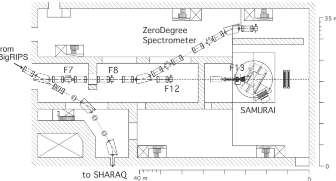
3.7 Top view of the experimental room view. . . 31
3.8 Magnified top view of the experimental room. . . 33
3.9 Bird’s-eye view of the experimental room with the definition of the coordinate. 34 3.10 Bird’s-eye view of the SAMURAI spectrometer. . . 35
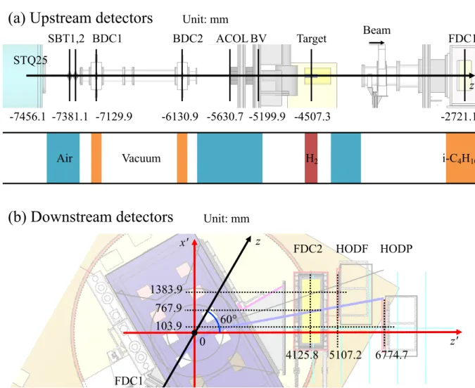
3.11 Side view of the upstream detectors and top view of the downstream detectors. . 37
3.12 Schematic views of the ACOL and the BV. . . 40
3.13 3D sectional drawing of the MINOS device. . . 43
3.14 Cross-sectional views of the MINOS around the target cell. . . 44
3.15 3D drawing of the RPD. . . 46
3.16 Cross-sectional views of the RPD. . . 47
3.17 3D drawing of the WINDS. . . 50
3.18 Layout of the WINDS. . . 51
3.19 Schematic view of the reconfigured DALI2 setup. . . 52 viii
3.20 Layout of the NEBULA. . . 53
3.21 Simplified circuit diagram of the beam trigger and the recoil proton trigger. . . 57
3.22 Circuit diagram for a trigger logic. . . 58
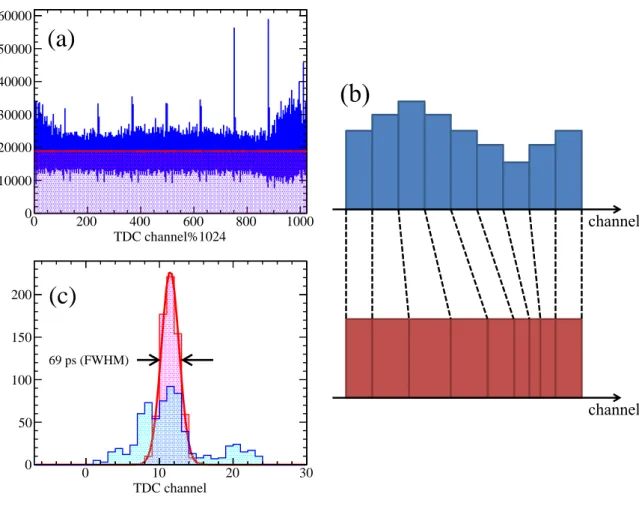
4.1 2D plot of time versus TDC channel in the REPIC RPC-180 module. . . 62
4.2 Time spectra for the differential nonlinearity correction of the V1290 module. . 63
4.3 Timing and light output correlation of SBT for the slew correction. . . 65
4.4 Drift time distributions of the MWDCs. . . 67
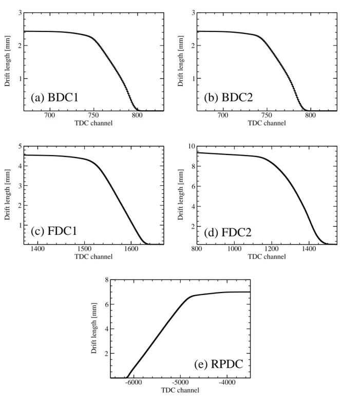
4.5 Conversion functions from the drift time to the drift length for the MWDCs. . . 69
4.6 Drift length distributions of the MWDCs. . . 70
4.7 Position distributions of bombarding particles at the center of the MWDCs. . . 72
4.8 Correlation between the drift lengths and the residuals for the MWDCs. . . 73
4.9 Residual distributions of the MWDCs. . . 74
4.10 Drift time distribution of the MINOS TPC and its derivative. . . 77
4.11 Tracking efficiency of the MINOS TPC. . . 78
4.12 Schematic view of the definition of the reaction point. . . 79
4.13 Differences between reconstructed reaction points in the x, y, and z directions. . 80
4.14 The minimum distance between11Li and proton tracks. . . 81
4.15 Reaction point r0distributions in the (z, x), the (z, y), and the (x, y) planes. . . 82
4.16 Schematic view of the event used for the slew correction of the RPTOF. . . 83
4.17 Time spectrum of the RPTOF for the slew correction. . . 84
4.18 TOF spectrum of RPTOF module for the TOF offset calibration. . . 85
4.19 Time resolution of the RPTOF as a function of the recoil proton momentum. . . 86
4.20 Correlation between energy and scattering angle of the recoil proton. . . 87
4.21 Hit pattern of the knocked-out neutron in the WINDS. . . 87
4.22 Schematic view of the event used for the slew correction of the WINDS. . . 89
4.23 Time spectrum of the WINDS for the slew correction. . . 90
4.24 TOF spectrum of WINDS for the TOF offset calibration. . . 91
4.25 Correlation between energy and scattering angle of the knocked-out neutron. . . 92
4.26 Hit pattern of the decay neutron in NEBULA. . . 93
4.27 Time spectrum of the NEBULA used for the slew correction. . . 94
4.28 Angular correlation between the recoil proton and the knocked-out neutron. . . 97
5.1 Flow charts of the data analysis for the PID and the momentum derivation. . . . 100
5.2 PID plots for the beam particles. . . 104
5.3 Top view of the SAMURAI detectors for heavy fragment. . . 105
5.4 PID plot for the heavy fragments. . . 107
5.5 PID plot for the recoil proton. . . 108
5.7 PID plot of the knocked-out neutron. . . 110
5.8 Doppler-corrected gamma-ray spectra of9Li and12Be. . . 111
5.9 Difference of the11Li beam momenta reconstructed by BigRIPS and SAMURAI. 115 5.10 Detection position distribution of the decay neutron. . . 117
5.11 Detection position distributions of the knocked-out neutron. . . 118
5.12 Momentum resolution of the knocked-out neutron. . . 119
5.13 Detection position distribution of the recoil proton. . . 121
5.14 Momentum and angular resolutions of the recoil proton. . . 123
5.15 Momentum difference d p distribution in the x, y, and z directions. . . 124
5.16 Angular distribution of the missing momentum in the polar angle. . . 129
5.17 Acceptance of the decay particles as a function of the relative energy. . . 130
5.18 Evaluated experimental acceptance as a function of the internal momentum kY. 132 5.19 Evaluated experimental acceptance as a function of the opening angle cosθY. . 133
5.20 Simulated resolutions of the internal momentum kY and the opening angleθY. . 136
5.21 Momentum transfer and missing momentum distributions. . . 139
6.1 Relative energy spectra for10Li obtained in this study and in the previous work. 142 6.2 Relative energy spectra for10Li with different regions. . . 144
6.3 Resonance parameters of p-wave resonance in10Li. . . 146
6.4 Two-dimensional plot of the relative energy versus the internal momentum. . . 151
6.5 Internal momentum kY distribution for each relative energy Erel. . . 152
6.6 Internal momentum kY distribution calculated by employing the DWIA. . . 153
6.7 Fraction of each multipole as a function of the relative energy. . . 155
6.8 Two-dimensional plot of the relative energy versus the opening angle. . . 158
6.9 Opening angle cosθY distribution for each relative energy Erel. . . 160
1.1 Static properties of Borromean nuclei. . . 4
1.2 List of physical quantities measured for the study of the11Li nucleus. . . 5
2.1 Integrated cross sections of different reactions on11Li. . . 19
3.1 List of beam line detectors in the BigRIPS. . . 24
3.2 Production parameters of the BigRIPS used in the present study. . . 26
3.3 Secondary beam intensity and purity for a 400-pnA primary beam. . . 28
3.4 Transfer matrix elements from F7 to F13. . . 30
3.5 Specifications of the SAMURAI magnet. . . 36
3.6 Specifications of the BDCs. . . 39
3.7 Count rates of the ACOL and the BV for a certain physics run. . . 41
3.8 Specifications of the FDC1 and the FDC2. . . 42
3.9 Specifications of the MINOS TPC. . . 45
3.10 Specifications of the RPDC. . . 48
3.11 Specifications of the WINDS. . . 50
3.12 Specifications of the DALI2. . . 52
3.13 Specifications of the NEBULA. . . 54
3.14 List of components of the DAQ system. . . 55
3.15 Summary of the experimental conditions. . . 59
4.1 Position resolutions and tracking efficiencies of the MWDCs. . . 71
4.2 List of combinations of two trajectories to obtain the reaction point. . . 80
5.1 Widths of the momentum difference d p in the x, the y, and the z directions. . . 137
6.1 Obtained resonance parameters for10Li. . . 145
6.2 Comparison of the resonance parameters for10Li. . . 145
6.3 Theoretical predictions of the10Li low-lying states. . . 147
6.4 Resonance parameters of predicted d-wave resonance states in10Li. . . 149
6.5 Parameters sets for calculating the distortion effect. . . 154
6.6 The fraction Sℓ j of each multipole. . . 156 xi
6.7 Expectation values of the opening angle in the position space. . . 162 B.1 Coefficient Cλ(ℓ, j, ℓ′, j′) up toℓ, ℓ′= 2. . . 171
Introduction
Atomic nucleus is a finite quantum many-body system consisting of two kinds of fermions, protons and neutrons. Two-particle correlation in nuclei is one of the attractive subjects of nuclear physics; it is closely related to the binding mechanism and the structures of nuclei.
The two-particle correlation in fermionic many-body systems has been successfully described by the Bardeen-Cooper-Schriefer (BCS) theory [1]. In conductive materials, two electrons compose the subsystems called Cooper pairs, which can be regarded as bosonic quasi-particles. At very low temperatures, they can condense in a single low-energy state and reduce the total energy of the system, so that the superconductivity appears. Through the same mechanism, the liquid3He and the ultra-cold Fermi gas of 6Li exhibit superfluidity [2, 3]. There are several experimental facts suggesting that the structures of open-shell nuclei can also be described by employing the BCS theory [4], such as the energy gap and the odd-even staggering.
The other kind of two-particle correlation, dineutron correlation is considered to appear in certain nuclei; it is one of the unique features of nuclei that has not been found so far in other fermionic many-body systems. When the binding strength between two neutrons is comparable to that of the neutron with respect to the nucleus, two neutrons are considered to form a spatially localized pair. In contrast to the BCS-type correlation where many nucleons around the Fermi energy surface constructively contribute to form the pairs, only specific two neutrons contribute to form the pair in the case of the dineutron correlation. The nature of the dineutron correlation is considerably different from that of the BCS-type correlation.
The dineutron correlation was first discussed by Migdal [5] by solving the three-body problem where two interacting light particles exist in a potential well produced by a heavy particle. He showed that under certain circumstances there appears a bound state of the two particles, even in the case when the attraction between the two particles is too weak to form a bound state outside the potential. Such circumstances are realized in certain nuclei. When the single-particle energies of two valence neutrons are close to zero, the interaction between two neutrons becomes important. The loosely-bound nuclei located at the neutron drip line such as
11Li are the best environments to satisfy such conditions.
In analogy with the dineutron correlation in the neutron drip-line nuclei, correlation between two protons, diproton correlation, in the proton-rich nuclei has also been discussed. However, the situation is more complicated in the case of two protons because the repulsive Coulomb interaction takes place. The foundation of the diproton correlation has not yet been fully clarified [6].
1.1
Borromean nucleus
11Li
The dineutron correlation is considered to appear in various nuclei. Shell-model calculation showed that two valence neutrons added to the doubly-magic nucleus208Pb may form a spatially localized pair. It is also shown that the dineutron correlation appears in medium-heavy neutron-rich nuclei [7, 8] and even in the neutron matter having an infinite number of constituents [9]. Weakly-bound light nuclei such as11Li and6He are the best suited systems because the dineutron correlation is considered to play a major role in their binding mechanism [10].
11Li and6He have the nature of Borromean [11]. Borromean nuclei are well described as a
three-body system and have no bound subsystem of either two of three constituents. Figure 1.1 schematically shows the Borromean nucleus11Li composed of9Li core and two valence neutrons. Although11Li is bound, its binary subsystems10Li and2n are unbound on their own.
11Li: bound 10Li: unbound 2n: unbound
Figure 1.1: Schematic view of the Borromean nucleus 11Li. The orange and the blue circles represent a core and two valence neutrons, respectively. The binary subsystems10Li and2n are unbound.
Theoretically, Borromean nuclei have been investigated by the core + n + n three-body models [6, 10, 12–23]. It is because the conventional shell model cannot reproduce the nature of the Borromean nuclei; The n–n interaction in such a loosely-bound system cannot be treated in the mean field approximation. It has been shown that such neutron-neutron correlation in the ground state is characterized as a spatially-localized neutron pair, i.e. dineutron correlation [10, 16–18]. Among the Borromean nuclei shown in Fig. 1.2, 11Li is regarded as a benchmark system. As summarized in Table 1.1,11Li has the largest root-mean-square (r.m.s.) matter radius, which
3
H
3He
4He
11Be
12Be
13B
14B
15B
14C
15C
16C
17C
18C
19C
20C
22C
7Be
8B
9C
10C
11C
8Li
9Li
12B
10Be
6Li
6He
8He
11Li
14Be
17B
19B
N
Z
7Li
12C
13C
9Be
11B
10B
1n
1H
2H
Figure 1.2: Part of the nuclear chart for Z ≤ 6 nuclei. The horizontal and the vertical axes show the neutron number N and the proton number Z, respectively. The boxes colored by black, gray, and orange represent stable, unstable, and Borromean nuclei, respectively.
is comparable even with those of A≈ 20 nuclei by employing the empirical formula of
R= r0A1/3, (1.1)
r0= 1.2 fm. (1.2)
The deviation of the r.m.s. matter radius of11Li from the systematics is also the largest among the Borromean nuclei as listed in Table 1.1. This large r.m.s. matter radius stems from the large neutron halo structure where valence neutrons are expected to be very loosely bound to the core. 11Li may be the nucleus having the smallest two-neutron separation energy S2n among all
the nuclei. The small S2n value of11Li of 369.3 keV also suggests a loosely-bound three-body
system. It is known that an admixture of configurations of single-particle orbits with different parities plays a significant role to form the spatial localization [24]. The contributions of s-and p-orbits in 11Li are considered as about 4:5 [25]. The comparable contributions of s-and p-orbits maximize the interference so that the spatial localization of two neutrons can be enhanced. Therefore, the11Li nucleus is considered as the best system to study the dineutron correlation.
Experimentally, a precise measurement of the nuclear charge radius provided an indirect evidence of the dineutron correlation. The nuclear charge radii of Li isotopes were measured [32, 33] by employing laser spectroscopy techniques [34, 35]. It was found that the r.m.s. charge radii monotonically drops from6Li (2.51 ± 6 fm) to9Li (2.22 ± 9 fm), and very rapidly, rises up to11Li (2.467 ± 37 fm). The rapid increase of the charge radii is considered as the effect of the recoil of the9Li core in11Li. Figure 1.3 schematically shows the mechanism of the increase of
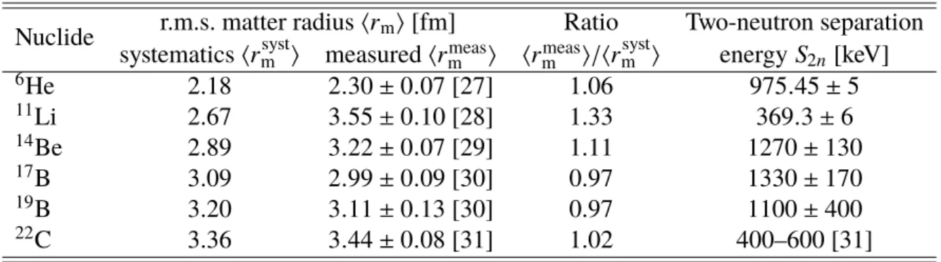
Table 1.1: Static properties of Borromean nuclei. The S2nvalues without citations were retrieved
from Ref. [26]. The⟨rmsyst⟩ values were calculated by using Eqs. (1.1) and (1.2).
Nuclide r.m.s. matter radius⟨rm⟩ [fm] Ratio Two-neutron separation systematics⟨rmsyst⟩ measured ⟨rmeasm ⟩ ⟨rmeasm ⟩/⟨rmsyst⟩ energy S2n [keV]
6He 2.18 2.30 ± 0.07 [27] 1.06 975.45 ± 5 11Li 2.67 3.55 ± 0.10 [28] 1.33 369.3 ± 6 14Be 2.89 3.22 ± 0.07 [29] 1.11 1270± 130 17B 3.09 2.99 ± 0.09 [30] 0.97 1330± 170 19B 3.20 3.11 ± 0.13 [30] 0.97 1100± 400 22C 3.36 3.44 ± 0.08 [31] 1.02 400–600 [31]
the charge radii. Due to the spatial localization of two valence neutrons, the9Li core in11Li must recoil to the opposite direction from the center of mass of the two neutrons so as to maintain the center of mass system of the whole system. The result supports the existence of the dineutron correlation in11Li, even though the interpretation strongly depends on nuclear models.
2.217±35 fm
9Li
2.467±37 fm
11Li
1.676±8 fm
4He
2.068±11 fm
6He
1.929±26 fm
8He
9Li
9Li
Figure 1.3: Schematic view of spatial configurations of Li isotopes. The orange and the blue circles represent 9Li and neutrons, respectively. The numbers denote the r.m.s. charge radii obtained by employing the laser spectroscopy techniques [33].
1.2
Studies on
11Li through nuclear reactions
With the development of the radioisotope (RI) beam facilities, it has become possible to study the dineutron correlation by using nuclear reactions. It was triggered by the discovery of the neutron halo structure in11Li through the measurement of the interaction cross section [36, 37]. Since then, the dineutron correlation in 11Li has been investigated through various kinds of physical quantities obtained using nuclear reaction, as listed in Table 1.2.
In the following subsections, first, an opening angle of two neutrons is introduced as a good measure of dineutron correlation in Sec. 1.2.1. Experimental evidences of the dineutron
Table 1.2: List of physical quantities measured for the study of the11Li nucleus. Physical quantity Reactions
E1 transition strength Coulomb breakup
Neutron momentum Neutron removal induced by a nuclear target Quasi-free neutron knockout
correlation are reviewed: the B(E1) measurement in Sec. 1.2.2, the momentum measurement in Sec. 1.2.3. Finally, the present knowledge is summarized in Sec. 1.2.4.
1.2.1
Opening angle as a measure of dineutron correlation
Employing the three-body model, one can define an opening angle as a measure of the dineutron correlation. Figure 1.4 shows a schematic view of 11Li composed of two valence neutrons and a 9Li core. When the dineutron correlation is developed, the opening angle between two neutrons with respect to the coreθVx gets closer to 0 degrees. The smaller opening angle shows the enhancement of the dineutron correlation. It should be noted that the opening angle is 90 degrees when the BCS-type correlation appears or two neutrons have no spatial correlation. There are two conventions of the coordinate, so-called Y and V to represent the three-body system. Depending on the choice of the coordinate system, we call the opening angleθYx orθVx. The definition of the coordinates is described in Sec. 2.3.
Neutron
Center of mass of
10Li
θ
x Yθ
x V 9Li
core
Figure 1.4: Schematic view of the11Li nucleus by employing the three-body model. The orange and the blue circles represent a9Li core and two valence neutrons, respectively. Two different definitions of the opening anglesθYx andθVx are shown. See the text for details.
1.2.2
B(E1) measurement
Strong soft electric dipole (E1) excitation is a characteristic phenomenon of halo nuclei, where significant E1 transition strength B(E1) appears at lower excitation energy. With the help of the
6 1. Introduction
cluster sum rule of the transition strength, this excitation mode has long been used as a tool to investigate the dineutron correlation in the ground state [38, 39].
The Coulomb breakup cross sections have been extensively measured so far for the deter-mination of the B(E1) value [40–54]. In the most recent work at RIKEN [40], the Coulomb breakup cross section of 11Li in the relative energy region of Erel ≤ 3 MeV, was obtained
with a lead target. The obtained spectrum is shown in the left panel of Fig. 1.5. Strong soft
E1 excitation was observed at about 0.6 MeV with B(E1) = 1.42 ± 0.18 e2fm2. By employ-ing the E1 cluster sum rule, the openemploy-ing angle of the two neutrons in 11Li was determined as ⟨θVx⟩ = 48+14−18 degrees. The obtained opening angle was significantly smaller than 90 de-grees expected for non-correlated two neutrons. Thus, strong dineutron correlation in11Li was suggested.
served in the Coulomb breakup of11Be [12], there is strong enhancement of the 11Li breakup yield at very forward angles. We have selected the angular region with !cm! !cut"# 1:46$%, corresponding to b & 20 fm, where first-order E1 Coulomb breakup dominates. The agreement with a pure E1 excitation calculation, shown by the solid curve, supports this assumption.
The B"E1% value is obtained, for these angle-selected data, by using the equivalent photon method [32,33] de-scribed by d2" d!cmdErel # 16#3 9@c dNE1"!cm; Ex% d!cm dB"E1% dErel ; (1)
where NE1"!cm; Ex% denotes the number of virtual photons with photon energy Ex at scattering angle !cm. Apply-ing this relation, with the photon number integrated over the selected angular range, the resulting B"E1% distribu-tion is shown by the solid circles in Fig. 3. In this proce-dure, the integration included the experimental angular resolution of 0.44$(1"). To obtain the photon energy Ex (#Erel' S2n), we adopted S2n# 300 keV from the 2003 mass evaluation [34]. Using the preliminary but more precise value of S2n# 376 ( 5 keV [35], the B"E1% value is enhanced by about 6%.
Figure 3 compares the present B"E1% distribution with the previous three data sets. Our new result reveals sub-stantial E1 strength that peaks at very low relative energies around 0.3 MeV. This feature is in sharp contrast to the previous data, which showed more reduced strength at low
energies. The present result also exhibits considerable strength extending to the higher energy region of a few MeV. This behavior of the B"E1% distribution leads to a large energy-integrated B"E1% strength of 1:42 ( 0:18 e2fm2 [4.5(6) Weisskopf units], for E
rel! 3 MeV, which is the largest soft E1 strength ever observed for atomic nuclei.
The difference of the present B"E1% distribution from those of earlier analyses is attributed to our enhanced sensitivity to low relative energies below Erel# 0:5 MeV compared to previous experiments, as is indicated in the efficiency curves of the current and GSI experiments [15] in Fig. 1(right). Inefficiency at low relative energies was also suggested for the previous RIKEN data where a cut for low 9Li-n relative velocities was necessary due to non-availability of a magnetic spectrometer at that time [14]. As for the MSU result, there is no obvious reason for inefficiency at low relative energies, although much re-duced efficiencies are apparent at Erel above 2 MeV, as shown in Fig. 1(right). A possible explanation of the re-duced strength below Erel# 0:5 MeV from the MSU data may be the importance of higher-order effects at the lower incident energy used, as suggested in Ref. [21]. We also note that the second bump observed in Zinser et al. is not seen in the spectrum with experimental significance.
In Fig. 3, the present B"E1% distribution is also compared with a calculation using the three-body model description of Esbensen and Bertsch [20], where the energy resolution (1") of "E # 0:17p!!!!!!!!ErelMeV in d"=dErel is taken into consideration. The model, which includes the two-neutron correlations in the initial and final states, is shown to reproduce the data very well without normalization adjust-ment. The agreement of both the spectral shape and
abso-FIG. 3. The B"E1% distribution obtained in the present work (solid circles) is compared with those from previous measure-ments [dotted-dashed line [13], solid histogram [14], dashed lines (zone) [15]]. The present data are also compared with the calculation (solid line) [20] which included the full n-n corre-lation.
FIG. 2. Breakup cross sections for 11Li' Pb at
70 MeV=nucleon as a function of the three-body relative energy for data with !cm! 5$. Inset: Angular distribution of11Li (the 9Li' n ' n c:m:) scattered by the Pb target in the range 0 !
Erel! 4 MeV. !gr denotes the grazing angle (2.34$). The
cal-culation using the equivalent photon method is shown by the solid curve.
PRL 96, 252502 (2006) P H Y S I C A L R E V I E W L E T T E R S 30 JUNE 2006week ending
252502-3
It is important to clarify the effect of the correlations in the
9Li core on the E1 strength distribution. For this purpose, we
compare our coupled-channel calculation including only the pairing correlation and that of the simple9Li + n + n model
assuming an inert 9Li core [26], which gives 20.6% of the
(s1/2)2component and −5.6 fm scattering length of the s-wave
state of 9Li-n. Both wave functions contain almost the same
amount of the s-wave component in the11Li ground state. In
two kinds of results, the E1 strength distributions commonly have peaks at around 0.5 MeV; however, there exists a large difference of strength around the peak energy. This is due to the fact that about 15% of the integrated strength in our calculation escapes to the higher excited11Li states having the
excited components of the9Li core.
From these comparisons, it is summarized that the large s-wave mixing in the initial ground state of11Li and the
corre-lations in the9Li core play essential roles in reproducing the
Coulomb breakup cross section, in particular, the position and the magnitude of the low-lying enhancement. Furthermore, the large s-wave mixing has a strong influence on the breakup mechanism. In our previous work [36], we discussed how the s-wave mixing in the ground state enhances the direct breakup process into the 9Li + n + n states instead of the sequential
one via the p-wave resonances in 10Li. In fact, when the
s-wave mixing is about 40% in the ground state, the three-body direct breakup process exhausts 66% of the integrated E1 strengths. This result is much different from the 6He case,
in which the sequential process via the5He(3/2−) resonance
dominates the breakup reaction [46]. This difference between
11Li and6He can be understood as the effect of two-neutron
s-wave component on the Coulomb breakup process. It should be noticed that the discussion of the breakup mechanism in Ref. [36] is based on the strength distribution calculated in CSM, in which the s-wave virtual states of 10Li cannot be
separated from the continuum states. Such a calculation cannot distinguish the sequential process via the s-wave virtual states from the direct breakup process. It is important to derive the invariant mass spectra of the9Li + n subsystem in order
to estimate appropriately the contribution of the sequential breakup process via the virtual state in the final states, which is shown in the next subsection.
In addition to the ground-state properties of11Li, it is also
interesting to see the effect of the final-state interaction (FSI) on the Coulomb breakup cross section. The FSI is defined in Eq.(14). In CSLS, all the effects of FSI in the scattering wave functions are included in the second term in Eq.(18). We can drop off the second term in the calculation of the cross section to examine the effect of FSI, while we do not change the initial ground-state wave function. The cross section without FSI is shown in Fig.5as red (gray) dashed line and has a broad peak structure at 0.5 MeV. It is found that the magnitude is much smaller than the full results including FSI, while there is a very small difference between two results in the higher energy region above 1 MeV. From this analysis, it is concluded that in addition to the initial-state properties of11Li, FSI gives a
significant effect to create the low-lying enhancement in the Coulomb breakup cross section of11Li. This large effect of
FSI has been shown in previous analyses [15,26,29] for the Coulomb breakups of11Li and6He.
0 0.5 1 1.5 2 2.5 3 0 0.5 1 1.5 2 2.5 3 dσ /dE [b/MeV] Energy [MeV] w/ FSI w/o FSI
FIG. 5. (Color online) Comparison between the calculated
Coulomb breakup cross sections of 11Li. The black (solid) line
represents the same result in Fig.3. The red (gray) dashed line is
the result without FSI.
C. Invariant mass spectra of binary subsystems of11Li
To see the effect of FSI in more detail, we calculate the invariant mass spectra using Eq.(26)in the Coulomb breakup reaction of 11Li. In Fig. 6, we show the results as functions
of the relative energies of9Li-n and n-n subsystems as panels
(a) and (b), respectively, together with the results calculated without FSI. It is found that both spectra have sharp peak struc-tures commonly below 0.1 MeV. From those results, the peaks in the invariant mass spectra are understood to come from FSI. In Fig.6(b), the peak seen in the n-n invariant mass spectra is
0 2 4 6 8 0 0.2 0.4 0.6 0.8 1 dσ /dE 9 Li-n [b/MeV] E9Li-n [MeV] w/ FSI w/o FSI (a) 0 2 4 6 8 0 0.2 0.4 0.6 0.8 1 dσ /dE n-n [b/MeV] En-n [MeV] w/ FSI w/o FSI (b)
FIG. 6. (Color online) Invariant mass spectra for 9Li-n and n-n
binary subsystems. The panels (a) and (b) represent the results for
9Li-n and n-n subsystems, respectively. The red (gray) solid lines
show the results with FSI and the black (dashed) ones are those without FSI.
034606-7
Figure 1.5: (Left) B(E1) distribution from11Li+ Pb at 70 MeV/nucleon. Taken from Ref. [40]. (Right) Calculated cross section of 9Li+ n system. The red solid and the black dashed curves show calculated cross sections with the final-state interaction (FSI) and those without the FSI, respectively. Taken from Ref. [23].
However, it has been shown that the measurement has uncertainties in extracting the infor-mation on the geometrical configuration of valence neutrons. Recent theoretical study [22, 23] indicated that the low-lying peak in the cross section is governed by final-state interactions (FSIs) and by the sequential decay via the core + n resonance. The right panel of Fig. 1.5 shows the calculated invariant mass spectrum, which is related to the E1 strength, with and without the FSIs. The shape of the E1 strength distribution is drastically changed with the presence of the FSIs. We note that the total E1 strength does not change even with the FSI; the existence of the FSI only affects the shape of the distribution. Experimentally, the total E1 cluster sum-rule strength is determined by the extrapolation from the measured strength in the lower energy region, because the experimental acceptance for the E1 strength is limited in the higher energy region. In the case of Ref. [40], the Coulomb breakup cross section was measured up to 3 MeV. The drastic change on the shape of the E1 strength must impact on the evaluation, resulting in
an unexpected large systematic uncertainty.
The other uncertainties come from the unbound core states. In the cluster sum rule, the core nucleus is assumed to be inert. This assumption is reasonable in the case of6He because the first excited state of the4He core is located above 20 MeV. However, it is not the case with
11Li, because the 9Li core can be easily excited; The first excited state is located at 2.7 MeV.
Kikuchi et al. [23] showed that the sum rule value should be reduced by about 15% due to the
9Li core excitation. By taking account the reduction, the opening angle⟨θx
V⟩ evaluated from the
data in Ref. [40] changes from 48+14−18degrees to 65± 11 degrees. This drastic change suggests a large model uncertainty or dependence in this method.
Bertulani and Hussein [55] proposed to use a different r.m.s. neutron-neutron distance, which was derived by employing the two-neutron correlation function [56]. They obtained the opening angle of⟨θVx⟩ = 66+22−18degrees from the data in Ref. [40]. Hagino and Sagawa [57, 58] showed that the effect of Pauli forbidden transitions [59] slightly changes the opening angle as ⟨θx
V⟩ = 65.2+11.4−13.0 degrees. Although the core excitation was not explicitly taken into account in
these analyses, the obtained opening angles unexpectedly agreed with the value discussed above. It implies the theoretical interpretation on the B(E1) measurement via the Coulomb breakup reaction has still not been finalized.
1.2.3
Momentum measurement
The neutron momentum distribution provides the most direct information on the spatial distri-bution of the valence neutrons [11].
By removing one of the two valence neutrons from11Li, the remaining system composed of a9Li core and a neutron immediately decays into two because of the Borromean nature. The momentum vectors of all the particles are measured so that the neutron momentum distribution is reconstructed.
There are two different kinds of probes for this method: a nuclear target such as a carbon and a proton target. These are described in the following subsections.
Neutron removal reaction with nuclear target
A carbon target was used in the neutron momentum measurement conducted at the GSI [60, 61]. In this experiment, the momenta of the removed neutron and of the target were not measured. The contributions of s- and p-orbits in the ground state were discussed by using the reconstructed angular distributions of the removed neutrons. The opening angle was determined as ⟨θYx⟩ = 76.6 ± 2.1 degrees. This result supported the dineutron correlation in11Li. We note that the obtained opening angle is defined in Y -coordinates and cannot be directly compared with that defined in V -coordinates used in the analysis of B(E1) measurements.
angle by employing the carbon-induced neutron removal reaction: the peripherality of the probe and the complexity of the reaction mechanism. These are explained in detail in Sec. 2.2.1.
Neutron knockout reaction with proton target
The proton-induced knockout reaction is more transparent and more simple than the removal reaction using the nuclear target. It is considered as one of the best probe to study the neutron-neutron correlation (Sec. 2.2).
A pioneering experiment was performed at GSI by using a liquid hydrogen target [62–64]. In this experiment, momentum of the knocked-out neutron was not measured. The data were analyzed in a similar way to the Refs. [60, 61]. However, for some unknown reasons, the opening angle distribution was not given.
1.2.4
Summary of knowledge
As described above, there have been extensive studies to search for dineutron correlation in
11Li. From an experimental point of view, most studies supported the existence of the dineutron
correlation in11Li. However, no studies could provide the spatial distribution of two neutrons in11Li, but only an “integrated” measure of the dineutron correlation. Moreover, the obtained opening angle, the measure of the dineutron correlation, was not consistent between different studies. For the further study, it is inevitable to consider following points which might cause uncertainties in the interpretation of the data.
Effect of the FSI.
The asymptotic momentum, which is observed experimentally, can be largely changed from that in the ground state by the effect of the FSI [22, 23].
Contributions of components with high angular momentum.
Catala et al. [24] demonstrated that an admixture of configurations of single-particle orbits with different parities plays a significant role to form the spatial localization. In the case of the11Li, the single-particle orbits with angular momentum ofℓ ≥ 2 is essential to form the dineutron correlation, even though their contributions in the11Li nucleus are expected to be 10% at most [65].
Core excitation.
A part of the9Li core in the ground-state11Li nucleus is considered to be excited [23, 66]. The core excitation changes the spatial configuration of the two valence neutrons through the Pauli blocking between the excited neutron in the core and the valence neutrons.
1.3
Thesis objectives
The purpose of this thesis is to investigate the spatial distribution of two valence neutrons in11Li via the quasi-free (p, pn) reaction at 246 MeV/nucleon followed by the neutron emission. We selected the Borromean nucleus11Li as the target because the dineutron correlation is considered to be strongly developed in this system. We employed the quasi-free (p, pn) reaction followed by the neutron emission because of the simplicity of the reaction mechanism, the minimization of the FSIs, and the transparency. This is the first kinematically complete measurement on11Li via the quasi-free (p, pn) reaction. The experiment was performed at the Radioactive Isotope Beam Factory (RIBF) in RIKEN, where an intense 11Li beam at intermediate energy and the thick proton target MINOS are available. The dedicated (p, pn) setup was newly constructed and combined with the SAMURAI spectrometer having a large acceptance and a multiple particle detection capability so as to realize the kinematically complete measurement.
The thesis is organized as follows: This chapter has provided a scientific background and motivation of this work. In Chap. 2, we describe the quasi-free (p, pn) reaction followed by the neutron emission, which is the key idea of this study. We then explain the requirements of this experiment. In Chap. 3, we describe the details of the experiment: the experimental facilities, the detectors, and the setup. In Chap. 4, we present the details of the detector calibration and performances. In Chap. 5, we present the details of the data analysis. In Chap. 6, we report the experimental results; we present the invariant mass, the internal momentum, and the opening angle distributions. We compare the results with previous works and theoretical calculations. Finally, in Chap. 7, we conclude this thesis.
The author is one of the spokespersons of the present experiment [67]. He led the collabora-tion from the planning phase, through the preparacollabora-tion and the beam time, and also in the analysis phase. He developed new method for the study of the neutron-neutron correlation, the quasi-free (p, pn) reaction followed by the neutron emission. He conducted the design and arrangement for all part of the experiment. He designed the supporting frame of the MINOS device for the coupling with the SAMURAI spectrometer. He newly designed two important detector sets, the recoil proton detector RPD and the knocked-out neutron detector array WINDS. He optimized the resolution and the detection efficiency including the geometrical acceptance. He arranged the new configuration of the gamma-ray detector array DALI2 to maximize the acceptance of recoil particle detectors. He designed the secondary beam production; The reduction of triton contaminant in the secondary beam was crucial in the present experiment. He constructed the active collimator ACOL and the beam veto BV so as to stop and to reject the tritons and unwanted beam particles. He rearranged the electronic circuit so as to install new detectors. He newly developed an auxiliary program to control the data acquisition system. Most of the analysis of the experimental data including the Monte-Carlo based simulation were done by the author, except for (i) the time projection chamber (TPC) of the MINOS, (ii) the gamma-ray detector array DALI2, and (iii) the part of the calibration of the neutron detector array NEBULA.
Experimental approach
In this work, the quasi-free (p, pn) reaction was employed to study the dineutron correlation in the Borromean nucleus11Li. This chapter describes our idea how we can approach the neutron-neutron correlation, why we selected the quasi-free (p, pn) reaction, and what is required for realizing the experiment; Sec. 2.1 explains our approach to the neutron-neutron correlation. Sec. 2.2 describes the method we employed: the quasi-free (p, pn) reaction followed by the neutron emission. Sec. 2.3 describes the definition of the coordinates used in this work. Finally, Sec. 2.4 lists the requirements for the present experiment.
2.1
Our approach to neutron-neutron correlation
The neutron-neutron correlation can be fully investigated by determining the spatial distributions of two valence neutrons in the ground state. However, it is experimentally difficult to measure the positions of two neutrons in the ground state at the same time because the FSIs take place in the decay process. In this thesis, we approached the spatial distributions of two valence neutrons in11Li by dividing the problem into two:
• Measurement of the one-neutron ground-state momentum and • Spectroscopy of the9Li+ n subsystem.
The one-neutron momentum distribution in the ground state provides the most direct information on the spatial distribution of the valence neutron of11Li [11]. On the other hand, the structure of the9Li+ n subsystem gives information on the interaction between a9Li nucleus and a neutron, which is essential to describe11Li, the9Li+ n + n system. By combining all the information (kinematically complete measurement), the spatial distribution of two neutrons are reconstructed as an opening angle distribution without losing the correlation information among them.
2.2
The quasi-free
(p
, pn) reaction followed by the neutron
emission
This section describe the quasi-free (p, pn) reaction followed by the neutron emission. This reaction has positive attributes due to the simplicity of the reaction mechanism, the minimization of the FSIs, the capability of the kinematically complete measurement, and the transparency. These are described in the following subsections.
A conceptual diagram of the reaction is shown in Fig. 2.1. One of the valence neutrons is knocked out by the probe proton. Thanks to the quasi-free scattering picture (Sec. 2.2.1), the motion between the knocked-out neutron and the residual can be well separated from that in the residual nucleus, and thus the reaction is hardly affected by the three-body FSI (Sec. 2.2.2). After the occurrence of the quasi-free (p, pn) reaction, the reaction residue immediately decays due to the Borromean nature. Therefore, it is possible to measure momentum vectors of all the constituents at the same time (Sec. 2.2.3). It should be noted that the quasi-free (p, pn) reaction is transparent so that one can probe the whole volume of the nucleus (Sec. 2.2.4).
Proton
Only two-body FSI
Core
Valence neutrons
Quasi-free (p,pn) reaction Neutron emission
Figure 2.1: Conceptual diagram of the quasi-free (p, pn) reaction followed by the neutron emission. The orange, the blue, and the red circles represent a core nucleus, valence neutrons, and a probe proton, respectively. See the text for details.
2.2.1
Simple reaction mechanism: quasi-free knockout
The measurement of the one-neutron ground-state momentum is one of the most crucial part of this work. One can reliably reconstruct the momentum distribution by employing the quasi-free (p, pn) reaction.
The quasi-free (p, pn) reaction is one of the specific case of the quasi-free knockout reactions. The electron-induced proton knockout (e, e′p) reaction is known as one of the most reliable
spectroscopic tool [68]. However, it is hardly applicable to the neutron knockout because neutrons have no electric charge. Therefore, the proton-induced nucleon knockout (p, pN)
reaction, where the nucleon-nucleon interaction takes place, becomes the best tool especially for the study of the neutron single-particle properties [69, 70].
The (p, pN) reaction can be quite simply described. Figure 2.2 shows a schematic view of the (p, pn) reaction in the normal kinematics. The incident proton knocks a neutron out of a target nucleus. Because the mean free path of nucleons in nuclear matter is same order of magnitude as the nuclear radius at the intermediate energy (100–1000 MeV) [71], the reaction is regarded as the quasi-free scattering (QFS) between the incident proton and the knocked-out neutron. Thanks to the simple kinematics, the missing momentum k is obtained owing to the momentum conservation law as
k = p′n+ p′p− pp. (2.1) θp θn pp p'p p'n k Target nucleus Proton beam Recoil proton Knocked-out neutron Missing momentum pt= 0
Figure 2.2: Schematic view of the (p, pn) reaction in the normal kinematics in the laboratory frame. The orange, the blue, and the red circles represent a target nucleus, a knocked-out neutron, and a probe proton, respectively. Momentum vectors of corresponding particles are shown by bold italic letters.
The (p, pN) reaction in normal kinematics has been well studied and sophisticated [72] at the Research Center for Nuclear Physics (RCNP), Osaka University. It has been shown that the knockout process is well described within a framework based on the Distorted Wave Impulse Approximation (DWIA) calculation [69]. The spectroscopic factors obtained by the (p, 2p) reaction agree with those determined by the (e, e′p) reaction with typically 20% accuracy. The
multipole decomposition analysis is possible to decompose the angular momentum.
QFS condition
The QFS condition guarantees the validity of the QFS picture in the knockout reaction. As described in the previous section, the QFS picture is essential in the (p, pn) reaction. The momentum transfer is a good barometer to confirm the QFS picture. The QFS picture is valid as
far as the momenta of incoming and outgoing nucleons are larger than those of typical nucleons. In the nucleus rest frame, the nucleon has a finite momentum distribution (missing momentum) due to the Fermi motion. The QFS condition can be satisfied by selecting the momentum transfer much larger than the missing momentum. The averaged missing momentum is 1.3 fm−1 in the case of well-bound nuclei [73]. Therefore, the momentum transfer of 2–2.5 fm−1is needed. On the other hand, the missing momentum in weakly bound nuclei is much smaller due to large spatial distribution. The averaged missing momentum of11Li is 0.5 fm−1 as we shall see later (Sec. 5.14). In such a case, the momentum transfer of larger than 1 fm−1 is considered to be enough for the QFS condition.
Comparison with neutron removal reaction using the nuclear target
r n P A A r n A* or A+n r r n P p r n p
Elastic breakup
Stripping
Quasi-free elastic
(a) Nuclear target
(b) Proton target
Figure 2.3: Schematic view of three kinds of processes in the neutron removal reactions (a) with a nuclear target and (b) with a proton target. The blue and the red circles represent neutrons and protons, respectively. The groups of nucleons indicated by “P”, “A”, and “r” represent a projectile, a target nucleus, and a residue, respectively.
There is the other kind of knockout reaction, the so-called removal reaction induced by the nuclear target. This reaction has been commonly used for the study of the single-particle properties [74]. Technically, the treatment of the nuclear target is much easier than that of the proton target. Moreover, the cross section of the nuclear-target-induced removal reaction is much larger than that of the proton-induced knockout reactions. However, the reaction mechanism in the removal reaction is more complex than that in the proton-induced knockout reaction. Figure 2.3 shows the reaction mechanisms in the neutron removal and knockout reactions. Two different kinds of processes can contribute to the removal reactions: the elastic breakup and the stripping processes. In the elastic breakup process, the projectile (P) breaks into a neutron (n) and a residue (r) by exchanging the momentum with a target nucleus (A). Some theoretical
models are available to describe this process, such as the Continuum-Discretized Coupled-Channel (CDCC) method [75, 76], the Dynamical Eikonal Approximation (DEA) [77, 78], the Faddeev–Alt-Grassberger-Sandhas (Faddeev–AGS) theory [79, 80], etc. On the other hand, in the stripping process, the residue and the target nucleus are excited and sometimes the neutron is picked-up by the target nucleus. Although the Glauber model [81] based on the Eikonal reaction theory (ERT) and adiabatic approximations has been developed [82, 83] for this process, the formulation of the parallel momentum distribution (PMD) of residual nucleus and the differential cross sections is not completed [84]. These processes are competitive and it makes the representation complicated [85].
2.2.2
Minimization of the FSIs
We explain the effect of the FSIs by taking the Coulomb breakup reaction as an example. Figure 2.4 shows a conceptual diagram of the Coulomb breakup reaction. A high-Z target, such as a lead, is used in this method to break the system by exciting the E1 transition in the nucleus. After the breakup, momentum vectors of all the decay particles can be measured. However, in the transient region, the FSIs between three constituents take place. Due to the three-body FSI, the observed momentum vectors in the final state (k′n1, k′n2, and k′r) cannot be traced back to those in the initial state (kn1, kn2, and kr). In other words, the momentum distribution in the
initial state is smeared and at least partly lost in the reaction.
E1
Three-body FSIγ
High-Z target kn1 kn2 kr k'n1 k'r k'n2Figure 2.4: Conceptual diagram of the Coulomb breakup reaction. The orange and the blue circles represent a core nucleus and valence neutrons, respectively. Momentum vectors of corresponding particles are shown by bold italic letters.
It should be emphasized that the suppression of the three-body FSI is crucial in the present experiment; In the presence of the three-body FSI, energies and momenta can be exchanged among two-body subsystems and thus the their correlations in the initial state can be easily lost. This does not take place in the two-body FSIs; It can be fully described by the Lippmann-Schwinger equation.
the valence neutrons in Borromean nuclei without interference in the remaining constituents. Then, only the two-body FSI takes place in the decay process, and therefore, the initial-state information can be extracted.
2.2.3
Kinematically complete measurement
The kinematically complete measurement, the measurement of all the particles involved in the reaction, is required in this work so as to reconstruct the neutron momentum distribution without any uncertainties. In addition, it is also important to investigate the contributions of core excitation component in the ground-state11Li [23].
Use of the proton target is essential for the kinematically complete measurement. The momentum transfer q and the energy transferω can be determined event by event without any uncertainties. One can reconstruct all the momentum vectors without any assumptions.
2.2.4
Transparency
For measuring the momentum distribution, it is important to use the transparent probe so as to investigate the neutron-neutron correlation over the whole nuclear volume. The quasi-free (p, pn) reaction is more transparent than the Coulomb breakup reaction as well as the neutron removal reaction induced by the nuclear target. Coulomb breakup reaction is peripheral because the operator of the Coulomb interaction is proportional to rn with n ≥ 1 [86]. In the case of the neutron removal reaction, a strong absorption from the nuclear target takes place. Recent theoretical calculation showed that the strength of the absorption from the nuclear target is 10 times larger than that from the proton target in the case of6He [73]. Only the quasi-free (p, pn) reaction can probe deeply into inner part of the nucleus.
2.3
Definition of coordinates
In the present study, the spatial correlation of three-body system (two neutrons and a core nucleus) is discussed. For the description of such a system, it is convenient to introduce so-called Jacobi coordinates based on the hyper-spherical basis [87]. Figure 2.5 shows schematic view of the definition of variables. In the beam rest frame, the positions of the 9Li core, the knocked-out neutron, and the decay neutron are denoted as rr, rn1, and rn2, respectively. The
Jacobi coordinates as RY = rn2− rr, (2.2) rY = rn1− mrrr+ mnrn2 mr+ mn , (2.3) cosθYx = RY · rY |RY||rY|, (2.4) where mnand mr represent the masses of the neutron and the9Li core, respectively. In a similar
way, the relative momentum vector KY and the internal momentum vector kY, and the opening
angle in momentum spaceθY are defined as follows:
KY = kn2− kr, (2.5) kY = kn1− mrkr+ mnkn2 mr+ mn , (2.6) cosθY = KY · kY |KY||kY|. (2.7) The opening angles in so-called V -coordinates are also used historically for describing the dineutron correlation [25, 40]. They are defined as
cosθVx = RY · (rn1− rr) |RY||rn1− rr|, (2.8) cosθV = KY · (kn1− kr) |KY||kn1− kr| . (2.9) Figure 2.5(b) shows the definition of the momentum vectors of all the particles in the laboratory frame. The momentum vectors of the 11Li beam ˜pb and the proton target pt are
defined before the occurrence of the reaction, while those of the recoil proton ˜pp, the
knocked-out neutron pn1, the decay neutron pn2, and the9Li heavy fragment ˜pr are defined after the
occurrence of the reaction.
The Lorentz transformation between the beam rest frame and the laboratory frame is defined by using the momentum vector of the11Li beam ˜pb.
Proton target 11Li beam Knocked-out neutron Recoil proton pp Heavy fragment 9Li Decay neutron pn2 pr pt= 0 pb pn1 ~ ~ ~
(b) Laboratory frame (in momentum space)
RY Knocked-out neutron Decay neutron rY Center of mass of 10Li θx Y θx V(a) Beam rest frame
rn2 rr rn1 KY kY θY θV kn2 kr kn1
(In coordinate space)
(In momentum space)
Beam
(c) Laboratory frame (in coordinate space)
Figure 2.5: Schematic view of the definition of variables. (a) Position and momentum vectors of the three constituents of 11Li. Relative position vectors (RY and rY), a relative momentum
vector (KY), and an internal momentum vector (kY) are defined. Opening angles between these
vectors are also defined (θVx andθYx for the position space,θV andθY for the momentum space).
(b) Momentum vectors of all the particles in the laboratory frame. They are defined at the reaction point, just before and just after an occurrence of the quasi-free (p, pn) reaction.
2.4
Experimental requirements
As discussed, the quasi-free (p, pn) reaction followed by the neutron emission is the best suited probe for the study of the dineutron correlation. Herein we summarize the experimental requirements for applying this method to the Borromean nucleus11Li.
Inverse kinematics.
11Li has a short half life of 8.75 ms. Thus, the quasi-free (p, pn) reaction should be
performed with11Li as the energetic projectile and a proton as the stationary target.
Intermediate energy.
The intermediate energy (100–1000 MeV) is best suited for the (p, pn) reaction, where the QFS picture is valid.
High luminosity.
High statistics measurement is required for the decomposition of the single-particle orbits with higher angular momentum.
The cross section of the quasi-free (p, pn) reaction is smaller by 1–2 orders of magnitude than those of the other reactions discussed above. Measured cross sections of those reactions on11Li are summarized in Table 2.1. The cross section of the Coulomb breakup reaction is the largest because the reaction is caused by the electromagnetic interaction. The cross section of the quasi-free (p, pn) reaction is smaller than that of the neutron removal reaction because only one probe proton contributes to the neutron knockout in the former case, while more than one nucleons of a target nucleus contribute to the neutron removal in the latter case.
In order to achieve a high luminosity, a high-intense beam and a thick proton target are needed.
Table 2.1: Integrated cross sections of different reactions on11Li.
Reaction Energy Integrated cross sectionσ [b]
[MeV/nucleon] for Erel ≤ 3 MeV for Erel ≤ 6 MeV
Coulomb breakup [40] 70 2.34± 0.05(stat) ± 0.28(syst) (not given)
Neutron removal [61] 264 0.15a (not given)
Quasi-free (p, pn) [64] 280 0.035a 0.041a
aData were read from figures in the articles.
Kinematically complete measurement.
For reconstructing the neutron momentum distribution, it is needed to determine the momentum vectors of all the particles without any assumptions such as the inert core.
It is inevitable to detect all the particles involved in the reaction including gamma-rays simultaneously.
In summary, the following four requirements should be satisfied practically: 1. High-intensity, intermediate-energy11Li beam,
2. Thick liquid hydrogen target,
3. Large acceptance spectrometer having multiple particle detection capability, and 4. Dedicated (p, pn) setup.
These are simultaneously available only at the RI Beam Factory at RIKEN; The accelerator complex and the following BigRIPS separator can provide a high-intensity11Li beam at inter-mediate energy. Thick liquid hydrogen target MINOS is available at RIKEN. The SAMURAI spectrometer has a large acceptance and a multiple particle detection capability, as well as a flexibility to be combined with the (p, pn) setup newly constructed for this study. Therefore, we performed the present experiment at the RIBF.

![Figure 3.2: Acceleration scheme of the RIBF accelerator complex in variable energy mode [89]](https://thumb-ap.123doks.com/thumbv2/123deta/8495343.922410/35.892.127.805.172.381/figure-acceleration-scheme-ribf-accelerator-complex-variable-energy.webp)