SUMMARY This paper presents a compact metal plate lens antenna for evaluating a wave absorber placed on ceiling of the ETC gate. The focal distance of the lens was derived to be 129 cm by the geometrical op- tics procedure. By arranging the lens in front of a horn antenna, the gain and beamwidth characteristics were improved from 18 dBi to 26 dBi and from 22 degrees to 7 degrees, respectively. Then the antenna characteris- tics were evaluated when the distance between the antenna and the lens was changed in order to miniaturize the lens antenna. As the result, the changes in beamwidth were held to within 1 dB when the lens came close to the horn antenna. Scattering, phase and electric field intensity of electromag- netic wave were evaluated to clarify the foundation of the given character- istics. It was found that the field intensity for the miniaturized lens antenna is stronger than that for GO designed one though the phase uniformity is worse. The distance between the horn antenna and lens can be reduced to 80 cm. The absorption characteristics for the arranged absorbers which have different absorptions were measured, and it was shown that the pro- posed method was suitable for specifying the deteriorated absorber in the ETC system.
key words: parallel-plate lens, geometrical optics (GO), diffraction, half power beam width (HPBW), wave absorber, electronic toll collection (ETC)
1. Introduction
Since the Electronic Toll Collection (ETC) went into ser- vice in March 2001, its users have been rapidly increasing.
At the end of December 2011, there were about 34 mil- lion ETC-equipped vehicles. ETC users now account for more than 85% of all vehicles on expressways in Japan [1].
The increase in the number of tollgate having several ETC lanes, has emphasized the key weakness of the system, the unwanted waves scattered from the wall or ground [2]. To improve the electromagnetic environments, wave absorbers are placed on the wall and ceiling of the tollgate. Therefore, it is necessary to measure the absorption characteristics for specifying aging degradation quantitatively.
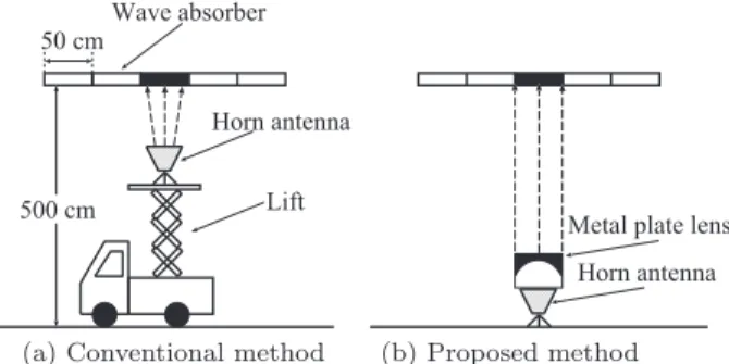
Figure 1 illustrates configurations for the absorber con- structed on the ceiling of the ETC gate. Figure 1(a) indicates a conventional method and (b) indicates proposed method in
Manuscript received March 5, 2012.
Manuscript revised June 14, 2012.
†The authors are with the Department of Electrical Engineer- ing and Electronics, Aoyama Gakuin University, Sagamihara-shi, 252-5258 Japan.
††The authors are with Nippon Expressway Research Institute Co., Ltd., Machida-shi, 194-8508 Japan.
a) E-mail: [email protected] b) E-mail: [email protected] c) E-mail: [email protected]
DOI: 10.1587/transcom.E95.B.3225
Fig. 1 Configurations for the panel of the absorber placed on the ceiling of the ETC gate.
this paper. The panel absorbers with the width of 50 cm are arranged on the ceiling with a height of about 500 cm above the ground, thus a deteriorated absorber should be irradi- ated with the antenna beam. For the measurements, a horn antenna with a wide beamwidth is ever used. The antenna needs to ride on a lift of a maintenance vehicle due to the wide beamwidth. In the case of a measurement from the ground, an antenna having a sharp beamwidth is needed.
Generally, these antennas, however, have some problems due to their large size and heavy weight.
A parallel beam lens which is typified by a dielectric lens is widely used to improve the antenna characteristics [3]
while remaining compact. However, the dielectric lens bring disadvantages for the measurements due to its heavy weight.
On the other hand, a metal plate lens has been reported [4].
The lens is cost-effective and light compared with the dielec- tric lens because the lens made of metal sheets and foamed polystyrenes [5], [6].
Figure 2 illustrates a metal plate lens antenna [6]. The metal plate lens consists of parallel placed metal plates in the E-plane with constant interval. To realize the plane wave, the metal plates are cut in order to achieve uniformed phase characteristics for electromagnetic (EM) waves transmitted through the lens. Thus the gain and directivity character- istics of the horn antenna are improved. Then the parame- ters of the lens are generally designed by geometrical optics (GO) [5] and the source of EM wave is treated as the virtual point source as shown in Fig. 2. The diffraction and reflec- tion from the lens antenna, however, are not considered in the GO design. Therefore EM field distribution would be different from those of the ray-trace.
It is necessary to study the antenna characteristics by Copyright c2012 The Institute of Electronics, Information and Communication Engineers
Fig. 2 Horn antenna with parallel-plate lens.
using EM simulator considering the diffraction and reflec- tion. In this paper, the EM behavior of the metal plate lens antenna is firstly presented. In Sect. 2, the metal plate lens is designed by GO, and the antenna performances are com- pared quantitatively with and without the lens by using EM field simulator. In Sect. 3, the gain and reflection charac- teristics will be shown when the distance between the horn antenna and the lens changes. The electric field distribution, phase and field intensity are evaluated to clarify the foun- dation of the given characteristics. Moreover, to specify the deteriorated wave absorber constructed at the ceiling of the ETC gate, the arranged absorbers having different absorp- tion are fabricated and measured in Sect. 4.
2. GO Design of the Parallel-Plate Lens
Figure 3 shows (a) side view and (b) front view of the metal plate lens. The lens consists of the metal plates and the foamed polystyrenes, whereDis a diameter of the lens and Lf is a focal distance between the virtual point source and the plate in the center. Each shape of the metal plates is de- cided by curvature radius ofR(θ) for each incident angleθ in other to conform the optical distance OPPto OQQ as shown in Fig. 3(a). In Fig. 3(b),bis the interval of the metal plates.
The parallel plate lens can be designed using GO as following equation;
Lf
λ0 = R(θ)
λ0 +Lf −R(θ) cosθ
λg (1)
whereλ0 is a wavelength in the vacuum andλg is wave- length in the guide between the parallel plates. Intervalb should be larger than half-wavelength due to a cutoff fre- quency of the guide, and a number of platesk(integer num- ber) is determined byDandb. ThenLf andR(θ) are given by
Lf = D
2 tan(W/2) (2)
R(θ)= (1−n)Lf
1−ncosθ (3)
Fig. 3 Structure of metal plate lens.
whereWis a half power beamwidth (HPBW) of the horn an- tenna in E-plane andnis a refraction index which is derived as follows;
n = λ0 λg =
1−λ0
2b 2
(4) Now, the lens is designed at the operational frequency f0 of 5.8 GHz (λ0 =5.2 cm) for the ETC system. A horn antenna (Keycom Corp.: Model RH159S, the size of the antenna aperture is 11.8×15.9 cm), is assumed where its HPBW is 22 degrees in E-plane and 24 degrees in H-plane [7]. With the given parameters ofD=50 cm andb=3 cm, Lf andkare determined from Eqs. (1)–(4) as 129 cm and 17, respectively. The position of the focus is calculated from W, and the height of the horn (11.8 cm), thus the distance between the aperture of the horn is calculated as 30 cm.
The radiation pattern of the designed lens antenna are evaluated by using HFSS (Ver.11.1, Ansoft Corp.) [8]. In the simulation, a model is simplified with PEC and PMC boundary condition considering symmetric property of the EM field. Then a wave port is set at the end of the horn. The size of the port is the same as the waveguide which is used for the measurements. Figure 4 shows the radiation pattern of the designed lens antenna in (a) E-plane and (b) H-plane.
The solid lines indicate the result with the lens and the dot- ted lines indicate that without the lens. As the results, by arranging the lens in front of the horn antenna, the gain and HPBW in E-plane were improved from 18 dBi to 26 dBi and from 22 degrees to 7 degrees, respectively. For H-plane the HPBW characteristic was also improved from 24 degrees to 7 degrees. However, the unwanted ripples taken along the radiation pattern without the lens are observed in the side- lobe for each plane. The radiation level at±90 degrees be- comes high for H-plane compared with the original one as shown in Fig. 4(b).
Then the gain characteristics were improved, but the unwanted ripples were observed. Here, GO design can- not factor in the diffraction of propagating EM field energy.
Thus, the distanceLbetween the antenna and lens is used as a variable number instead of Lf, and an optimum distance ofLwill be studied at next section.
Fig. 4 Radiation pattern of the designed lens antenna.
3. Miniaturization of the Lens Antenna by EM Simu- lation
3.1 Gain and Reflection Characteristics
To miniaturize the lens antenna, an optimum distance ofL is studied. Figure 5 shows the reflection and gain charac- teristics at 5.8 GHz whenL changes, where Lof 40 cm is the minimum distance without contact. It is found that the change of the gain is within 1 dB with the reduction of dis- tance up to 49 cm (almost 10λ0) even though the reflec- tion is increased from−15 dB to−10 dB. In the case ofL is less than 80 cm, the gain is reduced and more than 5 dB reduction is observed with the distanceLof 40 cm despite the reflection level is slightly decreased. Similarly, both the gain and reflection are decreased whenLis increased from 129 cm.
3.2 EM Behavior
For clarifying the foundation of the given characteristics as shown in Fig. 5, a scattering, phase and field intensity of electromagnetic wave for each distance Lare discussed in this section.
Fig. 5 Gain and reflection characteristics whenLchanges.
Fig. 6 Electric field distribution in E-plane whenLchanges.
Figure 6 illustrates the electric field distribution in E- plane with L of (a) 129 cm, (b) 80 cm, and (c) 40 cm in a same range. ThenLis the distance between the lens and the virtual point source. From these results, the scattering from the incidence plane of the lens becomes large with the small Las shown in Fig. 6(c). Thus it is found that the reflected power returned to the horn antenna is decreased whenLis less than 80 cm due to the scattering. In addition, the reduc- tion of the gain might be occurred because of the increased sidelobe level including the backlobe due to the scattering.
Fig. 7 Electric field distribution in H-plane whenLchanges.
On the other hand, the diffraction are observed in Fig. 6(a) thus the input energy for the lens might be lower than the other results.
The uniformity of the phase characteristics in the each guide are studied. Figure 7 shows the electric field distri- bution in H-plane withLof (a) 129 cm, (b) 80 cm, and (c) 40 cm. From Fig. 7(c), it is found that the radiated energy from the horn antenna is introduced to only the inside guides and phases between the guides are not uniform. The equi- phase plane is the most uniformed whenL=129 cm in the results. It is thought that the original focal distanceLf cal- culated by GO is most suitable to re-emit the electric power effectively. Thus, we evaluated the field intensity and phase characteristics on the edge of the lens as shown in Fig. 7.
Figure 8 shows the electrical field intensity and phase characteristics on the edge of the lens versus the distance from the center of the lens. In this figure,Lis set as 80 cm and 129 cm, where the vertical dotted lines indicate the po- sitions of the metal plates. As the results, the field intensity withL=80 cm is stronger than that withL=129 cm and the difference is increased when the distance is lessened. How- ever, the phase shifting in the results ofL=80 cm is larger than those ofL=129 cm. Therefore, the change of the gain characteristics are rather stable with the reduction of the dis- tance up to 49 cm.
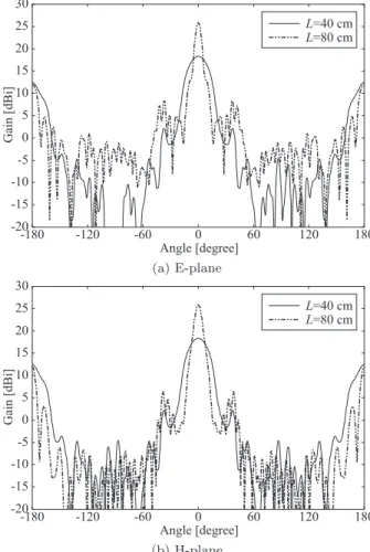
The radiation patterns in (a) E-plane and (b) H-plane
Fig. 8 Electrical field intensity and phase characteristics on the edge of the lens.
Fig. 9 Radiation pattern whenLchanges.
withLof 40 cm and 80 cm are shown in Fig. 9. From these results the ripples are observed in both planes which is same as Fig. 4. Although the backlobe level increases, the gain is kept as 26 dBi in the main beam with the parameterLof 80 cm.
3.3 Measurement of Beamwidth
The designed lens antenna was fabricated and the HPBW
Fig. 10 Half power beam width characteristics whenLchanges.
was measured in an anechoic chamber.
Figure 10 illustrates the measured and simulated HPBW characteristics in the both planes. In the figure the target HPBW for each distanceLis also shown. Then the HPBW is compared with the target for specifying the dete- riorated absorber placed at ceiling of the ETC gate. The tar- get is calculated from the distance between the ceiling of the tollgate and the forefront of the antenna where the height of the antenna includes that of a tripod stand for clamping. In this measurement, a turntable is used and turn around with 1 degree step, thereby the measured results have the angle resolution of±1 degree. The front of the horn antenna is set at the center of the turntable and the distance between received antenna is as 300 cm. From Fig. 10 the measured results agree well with the simulated ones and are satisfied the our target whenL is shortened from 129 cm to 80 cm.
Therefore the minimum distance can be decided as 80 cm.
4. Evaluation of Wave Absorber
Figure 11 shows the photograph of the fabricated antenna with the parameterL of 80 cm. The lens made of the alu- minum tapes and the foamed polystyrenes where the weight is only 4.9 kg including the horn antenna, and thus the fab- ricated antenna is compact and portable. For heading the
Fig. 11 Photograph of the fabricated metal plate lens antenna.
Fig. 12 Configuration of absorption measurements when the distance be- tween the lens and absorberdchanges.
Fig. 13 Measured absorption characteristics whendchanges.
antenna for the zenith direction and adjust the both centers of the lens and horn antenna, the horn is embedded to the foamed polystyrenes.
By using the lens antenna, the absorption characteris- tics of a fabricated Salisbury screen absorber [9] is measured by changing the distance between the lens antenna and the absorberd as shown in Fig. 12. The dimension of the fab- ricated absorber is 50 cm ×50 cm. A resistive film with the resistance of 400Ωis applied to the fabrication, and a thickness of the absorber is optimized in order to realize the matching frequency near 5.8 GHz. Figure 13 presents the measured absorption characteristics when the distance dchanges from 250 cm to 350 cm. The calculated result by
Fig. 14 Configuration for specifying the deteriorated absorber.
Fig. 15 Photograph of the fabricated absorbers.
the transmission line theory is also shown in the figure. Then the distance between the virtual point source and the lens is set as 80 cm as same as the simulation. From the results, only the fine differences are observed and these peak values agree well with the calculated one. The difference is within 0.5 dB at 5.8 GHz for each result. The calculated result is about 1 dB higher than measured results. The difference is caused by the size of the absorber which is not enough for the wavelength. Thus it is better to select the short distance dwhich satisfy the far-field condition.
Then the specifying of the deteriorated absorber is per- formed by using arranged three different absorbers. Fig- ure 14 illustrates the configuration for specifying the de- teriorated absorber. A resistive film with 588Ωis used as the deteriorated absorber and arranged in the center where the two absorbers in the both sides are the same as pre- vious study. The deteriorated absorber has 13 dB absorp- tion at a matching frequency by the transmission line the- ory. To keep down the dispersion, the lens antenna is po- sitioned with the distance of 250 cm from the absorbers as shown in Fig. 14. Then the absorptions are measured when the antenna is swept as froml=0 tol=50 cm. The photo- graph of the fabricated absorbers are shown in Fig. 15. In
Fig. 16 Absorption characteristics whenlchanges.
this measurement, the absorbers are arranged on a foamed polystyrenes and it is done in the horizontal direction.
Figure 16 shows the measured absorption characteris- tics when the distancel changes. The original absorption is also shown in the figure where the characteristic is the same as Fig. 13. Note that the absorption characteristics are slightly changed withland the absorption level agree with the theoretical one whenlis 50 cm. It is thought that the dis- persion is caused by the size of the absorber which is small compared with the wavelength. In addition, the sidelobe including the ripples shown in Fig. 9 is not influenced the measurements. From these results, it is found that the dete- riorated absorber can be specifying by the proposed method.
5. Conclusion
A measurement method using a compact metal plate lens antenna for the specification of a deteriorated wave absorber constructed on ceiling of the ETC gate has been presented in this paper. A focal distance of the lens Lf was derived as 129 cm by using geometrical optics design procedure.
By arranging the lens in front of a horn antenna, the gain and beamwidth characteristics were improved from 18 dBi to 26 dBi and from 22 degrees to 7 degrees, respectively.
Then the antenna characteristics were evaluated when the distance between the antenna and the lens changes in or- der to miniaturize the length of the lens antenna. As the results, the differences of the beamwidth were within 1 dB when the lens came close to the horn antenna. To clarify the foundation of given characteristics, the electric field dis- tribution was studied. It was found that the electrical field intensity for the miniaturized lens antenna is stronger than that for GO design one though the phase uniformity become worse. The absorption characteristics for the arranged ab- sorbers which have different absorption were measured. It was demonstrated that the proposed method is suitable for specifying the deteriorated absorber in the ETC system.
Acknowledgment
This work was supported by a Grant-in-Aid for The Pri-
vol.53, no.9, pp.2726–2731, Sept. 2005.
[3] Y. Zhang, J. Wang, Z. Zhao, and J. Yang, “Numerical analysis of di- electric lens antennas using a ray-tracing method and HFSS software,”
IEEE Antennas Propag. Mag., vol.50, no.4, pp.94–101, Aug. 2008.
[4] E. Jehamy, G. Landrac, and M.M. Ney, “Focusing element aberra- tion reduction procedure: Application to spherical metal plate lenses,”
Proc. German Microw. Conf. 2005, pp.82–85, April 2005.
[5] P. Wade, “Metal-plate lens antennas,” http://www.qsl.net/n1bwt/ chap3.pdf, accessed Dec. 2011.
[6] E. Jehamy, G. Landrac, and M.M. Ney, “Phase errors reduction pro- cedure for new anenna shapes: Application to wide scan angle multi beam metal plate lenses,” Int. Symp. Ant. Propag. 2005, pp.225–228, Aug. 2005.
[7] Keycom Corporation, “Rectangle horn antennas,” http://www.key com.co.jp/eproducts/ant/ant1/page.htm, accessed Feb. 27, 2011.
[8] High Frequency Structure Simulator (HFSS), Ansoft Corporation, Pittsburgh, PA, 2008.
[9] W.W. Salisbury, “Absorbent body for electromagnetic waves,” U.S.
Patent 2, 599, 944, June 1952.
Takenori Yasuzumi received the B.E. and M.E. degrees from Aoyama Gakuin University, Tokyo, Japan in 2007 and 2009, respectively. He is now a doctor student in the Department of Electrical Engineering and Electronics, Aoyama Gakuin University, Japan. He is currently in- terested in the design and development of mi- crowave filters, phased array antennas, wave ab- sorber and shield materials.
Nayuta Kamiya received the B.E. degree from Aoyama Gakuin University, Tokyo, Japan in 2012. He is now a master student in the Department of Electrical Engineering and Elec- tronics, Aoyama Gakuin University, Japan. He is currently interested in the study of improving the antenna characteristics using a metal plate lens antenna.
Osamu Hashimoto received B.E. and M.E. degrees in applied electronics engineering from the University of Electro-communications, Japan in 1976 and 1978, respectively and doc- torate degree from Tokyo Institute of Technol- ogy, Japan in 1986. In 1978, he joined Toshiba Corporation. In 1981, he joined the Defense Technical Development Laboratory. In 1991, he moved to the Department of Electrical Engineer- ing and Electronics, Aoyama Gakuin University, Japan as an associate professor, where he is cur- rently a professor. From 1994 to 1995, he was with University of Illinois as a guest researcher. Since April 2006, he has been serving as the President of Microwave Society of Institute of Electronics, Information, and Commu- nication Engineers (IEICE) in Japan. He has been engaged in research on microwave and millimeter-wave absorbers, planar filters, measurement and analysis of radar cross-sections. In 1990, he was awarded an excellent de- fense paper and in 2003, he received the excellent paper award from Japan Institute of Electronics Packaging. He is the author/co-author of more than ten books in Japanese including “Introduction of microwave absorber”, and
“Introduction of finite-difference time-domain method”. He is a member of the IEEE, IEEJ, and JIEP. He has published more than 400 papers in the re- viewed journals and international conferences.
Yukinori Matsushita received B.E. and M.E. degree in Electrical and Communication Engineering from Tohoku University, Miyagi, Japan in 1992 and 1994, respectively. He is a professional in the information and communi- cation field since being employed by the Japan Highway Public Corporation in 1994. His cur- rent responsibilities include ETC, VICS, and In- telligent Transport System. He is an Engineer of East Nippon Expressway Company Limited, and is now a Chief researcher of ETC division at Nippon Expressway Research Institute Company Limited.
Yasuyuki Matsuda received B.E. and M.E.
degree in Electronics and Communication En- gineering from Okayama Prefectural University, Okayama, Japan in 1997 and 1999, respectively.
He is a professional in the information and com- munication field since being employed by the Japan Highway Public Corporation in 1999. His current responsibilities include ETC, VICS, and Intelligent Transport System. He is an Engineer of Central Nippon Expressway Company Lim- ited, and is now a Researcher of ETC division at Nippon Expressway Research Institute Company Limited.